length NISSAN ALMERA 2001 Owner's Guide
[x] Cancel search | Manufacturer: NISSAN, Model Year: 2001, Model line: ALMERA, Model: NISSAN ALMERA 2001Pages: 2898, PDF Size: 60.76 MB
Page 1265 of 2898
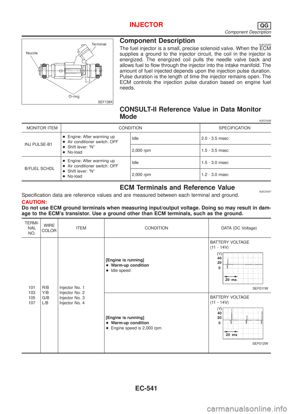
SEF138X
Component DescriptionNJEC0435The fuel injector is a small, precise solenoid valve. When the ECM
supplies a ground to the injector circuit, the coil in the injector is
energized. The energized coil pulls the needle valve back and
allows fuel to flow through the injector into the intake manifold. The
amount of fuel injected depends upon the injection pulse duration.
Pulse duration is the length of time the injector remains open. The
ECM controls the injection pulse duration based on engine fuel
needs.
CONSULT-II Reference Value in Data Monitor
Mode
NJEC0436
MONITOR ITEM CONDITION SPECIFICATION
INJ PULSE-B1+Engine: After warming up
+Air conditioner switch: OFF
+Shift lever: ªNº
+No-loadIdle 2.0 - 3.5 msec
2,000 rpm 1.5 - 3.5 msec
B/FUEL SCHDL+Engine: After warming up
+Air conditioner switch: OFF
+Shift lever: ªNº
+No-loadIdle 1.5 - 3.0 msec
2,000 rpm 1.2 - 3.0 msec
ECM Terminals and Reference ValueNJEC0437Specification data are reference values and are measured between each terminal and ground.
CAUTION:
Do not use ECM ground terminals when measuring input/output voltage. Doing so may result in dam-
age to the ECM's transistor. Use a ground other than ECM terminals, such as the ground.
TERMI-
NAL
NO.WIRE
COLORITEM CONDITION DATA (DC Voltage)
101
103
105
107R/B
Y/B
G/B
L/BInjector No. 1
Injector No. 2
Injector No. 3
Injector No. 4[Engine is running]
+Warm-up condition
+Idle speedBATTERY VOLTAGE
(11 - 14V)
SEF011W
[Engine is running]
+Warm-up condition
+Engine speed is 2,000 rpmBATTERY VOLTAGE
(11 - 14V)
SEF012W
INJECTORQG
Component Description
EC-541
Page 1345 of 2898
JEF360Y
JEF361Y
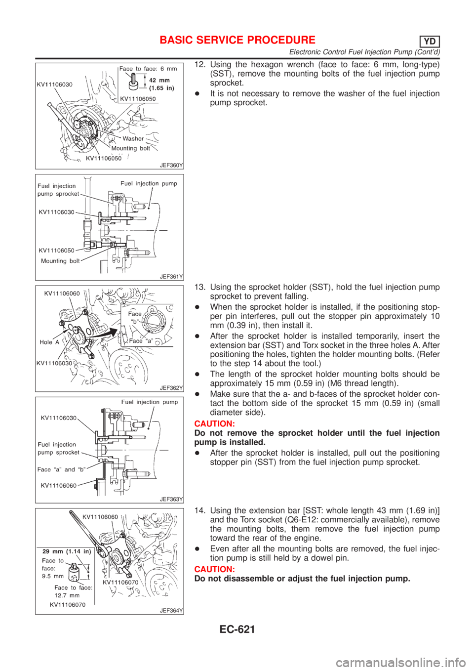
12. Using the hexagon wrench (face to face: 6 mm, long-type)
(SST), remove the mounting bolts of the fuel injection pump
sprocket.
+It is not necessary to remove the washer of the fuel injection
pump sprocket.
JEF362Y
JEF363Y
13. Using the sprocket holder (SST), hold the fuel injection pump
sprocket to prevent falling.
+When the sprocket holder is installed, if the positioning stop-
per pin interferes, pull out the stopper pin approximately 10
mm (0.39 in), then install it.
+After the sprocket holder is installed temporarily, insert the
extension bar (SST) and Torx socket in the three holes A. After
positioning the holes, tighten the holder mounting bolts. (Refer
to the step 14 about the tool.)
+The length of the sprocket holder mounting bolts should be
approximately 15 mm (0.59 in) (M6 thread length).
+Make sure that the a- and b-faces of the sprocket holder con-
tact the bottom side of the sprocket 15 mm (0.59 in) (small
diameter side).
CAUTION:
Do not remove the sprocket holder until the fuel injection
pump is installed.
+After the sprocket holder is installed, pull out the positioning
stopper pin (SST) from the fuel injection pump sprocket.
JEF364Y
14. Using the extension bar [SST: whole length 43 mm (1.69 in)]
and the Torx socket (Q6-E12: commercially available), remove
the mounting bolts, them remove the fuel injection pump
toward the rear of the engine.
+Even after all the mounting bolts are removed, the fuel injec-
tion pump is still held by a dowel pin.
CAUTION:
Do not disassemble or adjust the fuel injection pump.
BASIC SERVICE PROCEDUREYD
Electronic Control Fuel Injection Pump (Cont'd)
EC-621
Page 2191 of 2898
scratches or seizure. If scratches or seizure is found, hone or
replace the cylinder block.
SEM150B
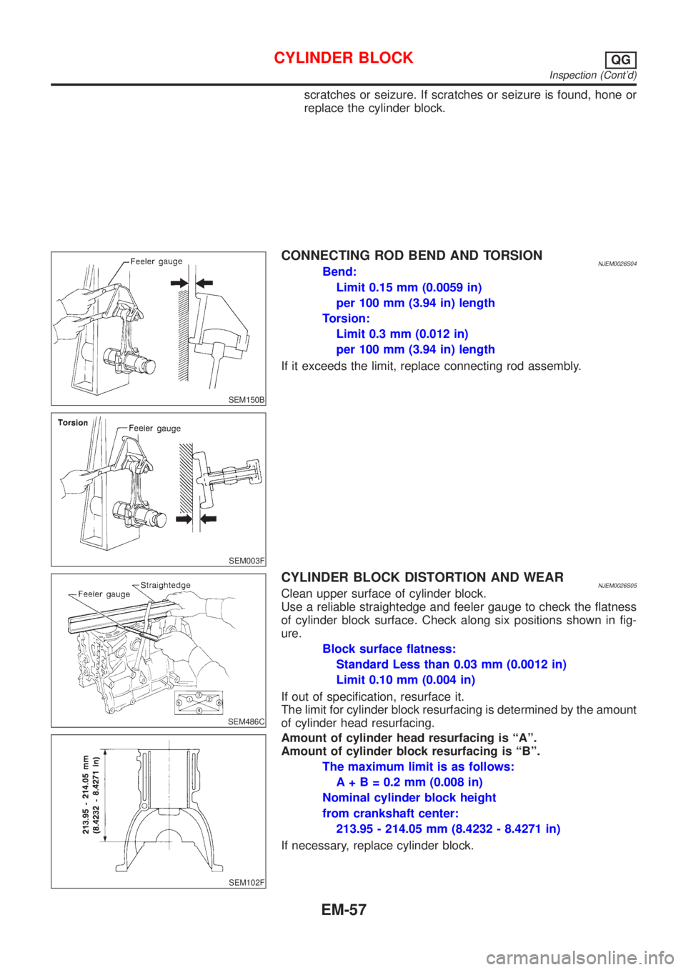
CONNECTING ROD BEND AND TORSIONNJEM0026S04Bend:
Limit 0.15 mm (0.0059 in)
per 100 mm (3.94 in) length
Torsion:
Limit 0.3 mm (0.012 in)
per 100 mm (3.94 in) length
If it exceeds the limit, replace connecting rod assembly.
SEM003F
SEM486C
CYLINDER BLOCK DISTORTION AND WEARNJEM0026S05Clean upper surface of cylinder block.
Use a reliable straightedge and feeler gauge to check the flatness
of cylinder block surface. Check along six positions shown in fig-
ure.
Block surface flatness:
Standard Less than 0.03 mm (0.0012 in)
Limit 0.10 mm (0.004 in)
If out of specification, resurface it.
The limit for cylinder block resurfacing is determined by the amount
of cylinder head resurfacing.
SEM102F
Amount of cylinder head resurfacing is ªAº.
Amount of cylinder block resurfacing is ªBº.
The maximum limit is as follows:
A + B = 0.2 mm (0.008 in)
Nominal cylinder block height
from crankshaft center:
213.95 - 214.05 mm (8.4232 - 8.4271 in)
If necessary, replace cylinder block.
CYLINDER BLOCKQG
Inspection (Cont'd)
EM-57
Page 2202 of 2898

ValveNJEM0031VALVENJEM0031S01Unit: mm (in)
SEM188A
QG15DE QG18DE
Valve head diameter ªDºIntake28.9 - 29.2
(1.138 - 1.150)29.9 - 30.2
(1.177 - 1.189)
Exhaust23.9 - 24.2
(0.941 - 0.953)24.9 - 25.2
(0.980 - 0.992)
Valve length ªLºIntake 92.00 - 92.50 (3.6220 - 3.6417)
Exhaust 92.37 - 92.87 (3.6366 - 3.6563)
Valve stem diameter ªdºIntake 5.465 - 5.480 (0.2152 - 0.2157)
Exhaust 5.445 - 5.460 (0.2144 - 0.2150)
Valve face angle ªaº45É15¢- 45É45¢
Valve margin ªTº1 (0.04)
Valve margin ªTº limitMore than 0.5 (0.020 in)
Valve stem end surface grinding limit 0.2 (0.008)
VALVE SPRINGNJEM0031S02
ModelFor Sedan For Hatchback
Free height mm (in) 41.2 (1.622) 40.0 (1.575)
Pressure N (kg, lb)
at height mm (in)Standard344.42 (35.12, 77.44)
at 25.26 (0.9945)370.0 (37.73, 83.19)
at 23.64 (0.9307)
Limit323.73 (33.01, 72.79)
at 25.26 (0.9945)347.8 (35.46, 78.19)
at 23.64 (0.9307)
Out-of-square mm (in)Less than 1.80 (0.0709)
VALVE LIFTERNJEM0031S10Unit: mm (in)
Valve lifter outside diameter 29.960 - 29.975 (1.1795 - 1.1801)
Lifter guide inside diameter 30.000 - 30.021 (1.1811 - 1.1819)
Clearance between valve lifter and valve lifter guide 0.025 - 0.065 (0.0010 - 0.0026)
SERVICE DATA AND SPECIFICATIONS (SDS)QG
Valve
EM-68
Page 2203 of 2898

VALVE CLEARANCE=NJEM0031S11Unit: mm (in)
For adjusting For checking
Hot Cold* (reference data) Hot
Intake 0.32 - 0.40 (0.013 - 0.016) 0.25 - 0.33 (0.010 - 0.013) 0.21 - 0.49 (0.008 - 0.019)
Exhaust 0.37 - 0.45 (0.015 - 0.018) 0.32 - 0.40 (0.013 - 0.016) 0.30 - 0.58 (0.012 - 0.023)
*: At a temperature of approximately 20ÉC (68ÉF)
Whenever valve clearances are adjusted to cold specifications, check that the clearances satisfy hot specifications and adjust
again if necessary.
VALVE GUIDENJEM0031S04Unit: mm (in)
MEM096A
Intake Exhaust
Standard Service Standard Service
Valve guideOuter diameter9.523 - 9.534
(0.3749 - 0.3754)9.723 - 9.734
(0.3828 - 0.3832)9.523 - 9.534
(0.3749 - 0.3754)9.723 - 9.734
(0.3828 - 0.3832)
Inner diameter
[Finished size]5.500 - 5.515 (0.2165 - 0.2171) 5.500 - 5.515 (0.2165 - 0.2171)
Cylinder head valve guide hole diameter9.475 - 9.496
(0.3730 - 0.3739)9.685 - 9.696
(0.3813 - 0.3817)9.475 - 9.496
(0.3730 - 0.3739)9.685 - 9.696
(0.3813 - 0.3817)
Interference fit of valve guide0.027 - 0.059
(0.0011 - 0.0023)0.027 - 0.049
(0.0011 - 0.0019)0.027 - 0.059
(0.0011 - 0.0023)0.027 - 0.049
(0.0011 - 0.0019)
Stem to guide clearance 0.020 - 0.050 (0.0008 - 0.0020) 0.040 - 0.070 (0.0016 - 0.0028)
Valve deflection limit (Dial gauge reading) 0.2 (0.008)
Projection length ªLº 11.5 - 11.7 (0.453 - 0.461)
AVAILABLE SHIMSNJEM0031S07
Thickness mm (in) Identification mark
2.00 (0.0787) 200
2.02 (0.0795) 202
2.04 (0.0803) 204
2.06 (0.0811) 206
2.08 (0.0819) 208
2.10 (0.0827) 210
2.12 (0.0835) 212
2.14 (0.0843) 214
2.16 (0.0850) 216
SERVICE DATA AND SPECIFICATIONS (SDS)QG
Valve (Cont'd)
EM-69
Page 2226 of 2898
JEM116G
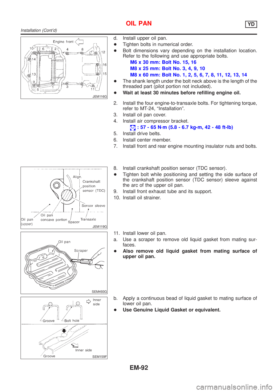
d. Install upper oil pan.
+Tighten bolts in numerical order.
+Bolt dimensions vary depending on the installation location.
Refer to the following and use appropriate bolts.
M6 x 30 mm: Bolt No. 15, 16
M8 x 25 mm: Bolt No. 3, 4, 9, 10
M8 x 60 mm: Bolt No. 1, 2, 5, 6, 7, 8, 11, 12, 13, 14
+The shank length under the bolt neck above is the length of the
threaded part (pilot portion not included).
+Wait at least 30 minutes before refilling engine oil.
2. Install the four engine-to-transaxle bolts. For tightening torque,
refer to MT-24, ªInstallationº.
3. Install oil pan cover.
4. Install air compressor bracket.
: 57 - 65 N´m (5.8 - 6.7 kg-m, 42 - 48 ft-lb)
5. Install drive belts.
6. Install center member.
7. Install front and rear engine mounting insulator nuts and bolts.
JEM119G
8. Install crankshaft position sensor (TDC sensor).
+Tighten bolt while positioning and setting the side surface of
the crankshaft position sensor (TDC sensor) sleeve against
the arc of the upper oil pan.
9. Install front exhaust tube and its support.
10. Install oil strainer.
SEM493G
11. Install lower oil pan.
a. Use a scraper to remove old liquid gasket from mating sur-
faces.
+Also remove old liquid gasket from mating surface of
upper oil pan.
SEM159F
b. Apply a continuous bead of liquid gasket to mating surface of
lower oil pan.
+Use Genuine Liquid Gasket or equivalent.
OIL PANYD
Installation (Cont'd)
EM-92
Page 2234 of 2898
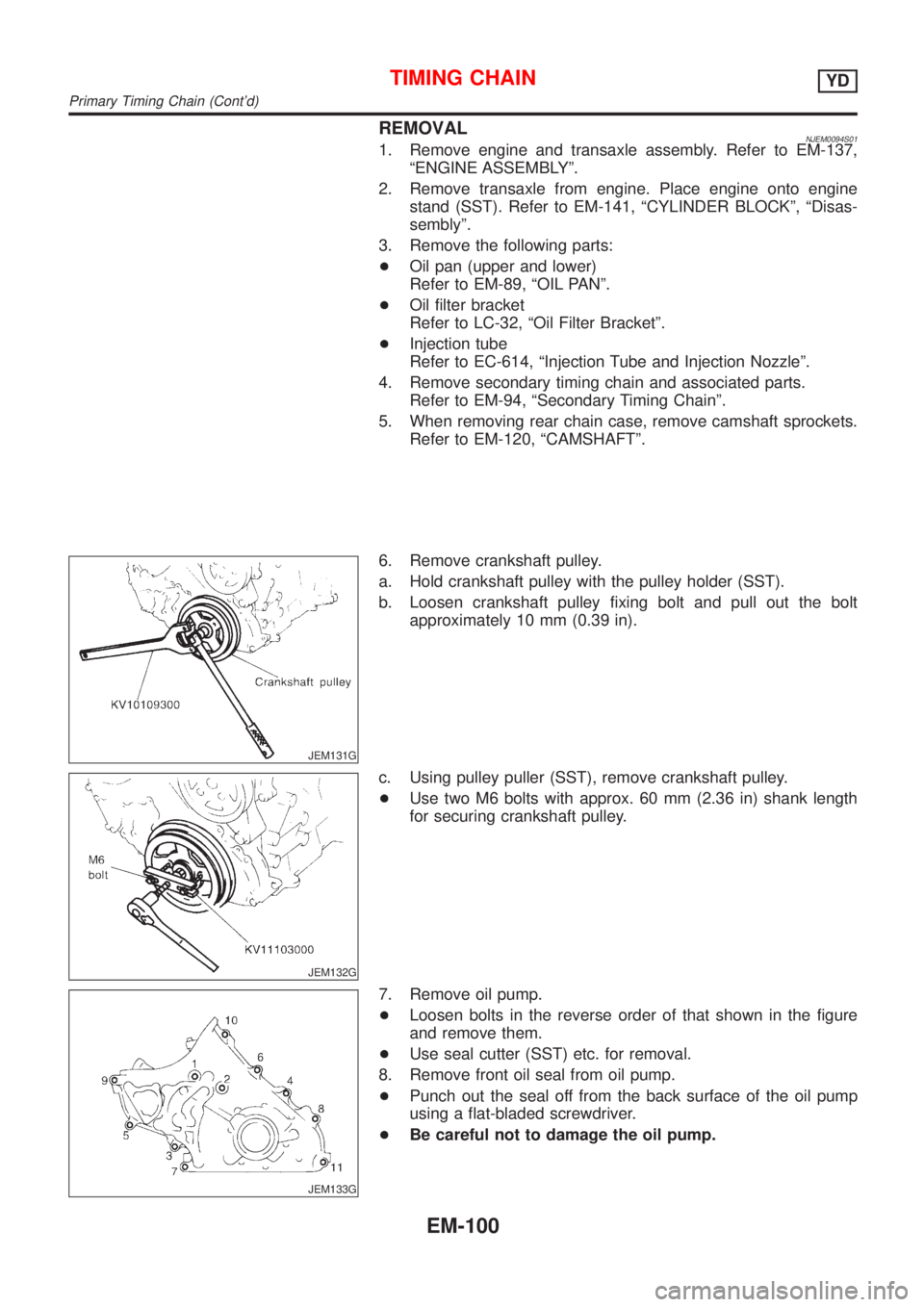
REMOVALNJEM0094S011. Remove engine and transaxle assembly. Refer to EM-137,
ªENGINE ASSEMBLYº.
2. Remove transaxle from engine. Place engine onto engine
stand (SST). Refer to EM-141, ªCYLINDER BLOCKº, ªDisas-
semblyº.
3. Remove the following parts:
+Oil pan (upper and lower)
Refer to EM-89, ªOIL PANº.
+Oil filter bracket
Refer to LC-32, ªOil Filter Bracketº.
+Injection tube
Refer to EC-614, ªInjection Tube and Injection Nozzleº.
4. Remove secondary timing chain and associated parts.
Refer to EM-94, ªSecondary Timing Chainº.
5. When removing rear chain case, remove camshaft sprockets.
Refer to EM-120, ªCAMSHAFTº.
JEM131G
6. Remove crankshaft pulley.
a. Hold crankshaft pulley with the pulley holder (SST).
b. Loosen crankshaft pulley fixing bolt and pull out the bolt
approximately 10 mm (0.39 in).
JEM132G
c. Using pulley puller (SST), remove crankshaft pulley.
+Use two M6 bolts with approx. 60 mm (2.36 in) shank length
for securing crankshaft pulley.
JEM133G
7. Remove oil pump.
+Loosen bolts in the reverse order of that shown in the figure
and remove them.
+Use seal cutter (SST) etc. for removal.
8. Remove front oil seal from oil pump.
+Punch out the seal off from the back surface of the oil pump
using a flat-bladed screwdriver.
+Be careful not to damage the oil pump.
TIMING CHAINYD
Primary Timing Chain (Cont'd)
EM-100
Page 2237 of 2898
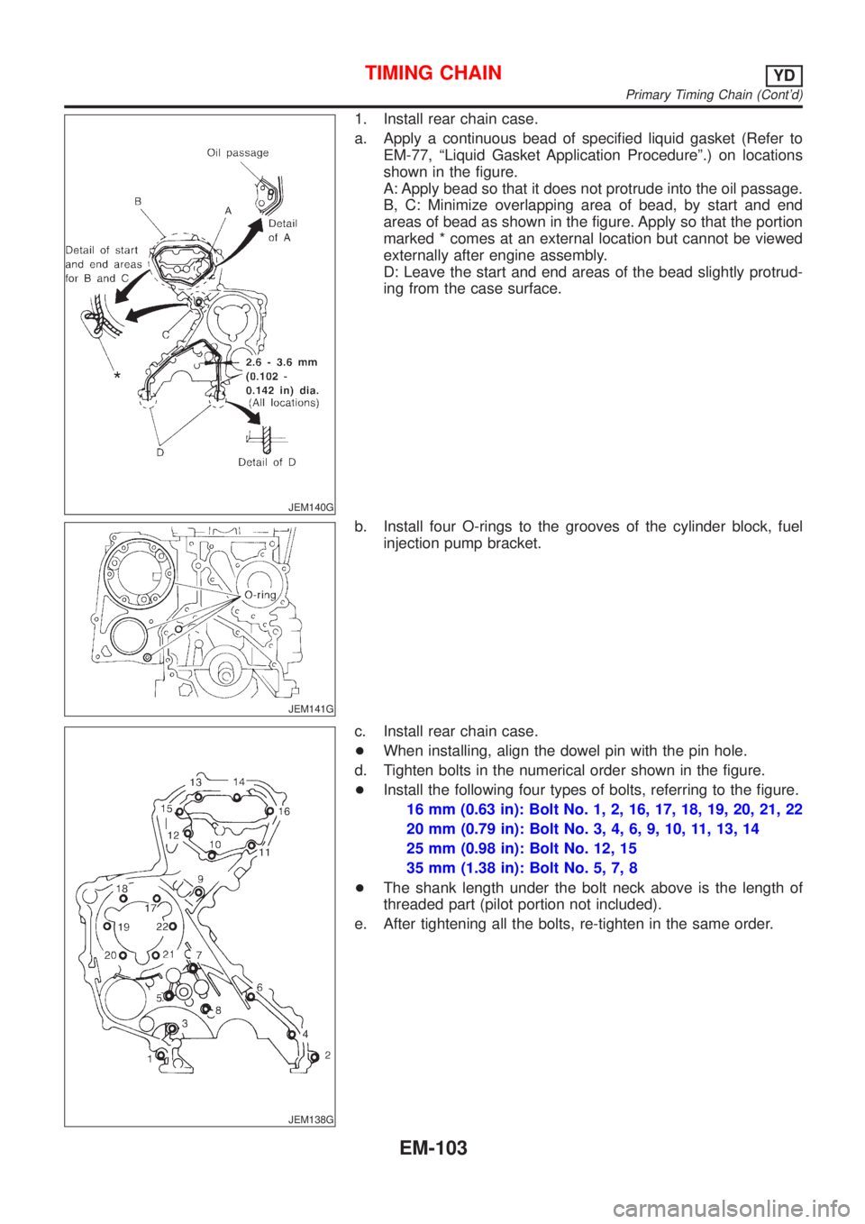
JEM140G
1. Install rear chain case.
a. Apply a continuous bead of specified liquid gasket (Refer to
EM-77, ªLiquid Gasket Application Procedureº.) on locations
shown in the figure.
A: Apply bead so that it does not protrude into the oil passage.
B, C: Minimize overlapping area of bead, by start and end
areas of bead as shown in the figure. Apply so that the portion
marked * comes at an external location but cannot be viewed
externally after engine assembly.
D: Leave the start and end areas of the bead slightly protrud-
ing from the case surface.
JEM141G
b. Install four O-rings to the grooves of the cylinder block, fuel
injection pump bracket.
JEM138G
c. Install rear chain case.
+When installing, align the dowel pin with the pin hole.
d. Tighten bolts in the numerical order shown in the figure.
+Install the following four types of bolts, referring to the figure.
16 mm (0.63 in): Bolt No. 1, 2, 16, 17, 18, 19, 20, 21, 22
20 mm (0.79 in): Bolt No. 3, 4, 6, 9, 10, 11, 13, 14
25 mm (0.98 in): Bolt No. 12, 15
35 mm (1.38 in): Bolt No. 5, 7, 8
+The shank length under the bolt neck above is the length of
threaded part (pilot portion not included).
e. After tightening all the bolts, re-tighten in the same order.
TIMING CHAINYD
Primary Timing Chain (Cont'd)
EM-103
Page 2280 of 2898
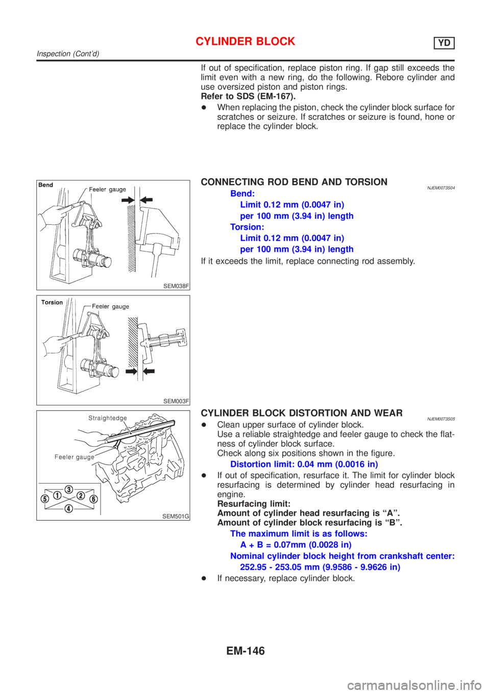
If out of specification, replace piston ring. If gap still exceeds the
limit even with a new ring, do the following. Rebore cylinder and
use oversized piston and piston rings.
Refer to SDS (EM-167).
+When replacing the piston, check the cylinder block surface for
scratches or seizure. If scratches or seizure is found, hone or
replace the cylinder block.
SEM038F
SEM003F
CONNECTING ROD BEND AND TORSIONNJEM0073S04Bend:
Limit 0.12 mm (0.0047 in)
per 100 mm (3.94 in) length
Torsion:
Limit 0.12 mm (0.0047 in)
per 100 mm (3.94 in) length
If it exceeds the limit, replace connecting rod assembly.
SEM501G
CYLINDER BLOCK DISTORTION AND WEARNJEM0073S05+Clean upper surface of cylinder block.
Use a reliable straightedge and feeler gauge to check the flat-
ness of cylinder block surface.
Check along six positions shown in the figure.
Distortion limit: 0.04 mm (0.0016 in)
+If out of specification, resurface it. The limit for cylinder block
resurfacing is determined by cylinder head resurfacing in
engine.
Resurfacing limit:
Amount of cylinder head resurfacing is ªAº.
Amount of cylinder block resurfacing is ªBº.
The maximum limit is as follows:
A + B = 0.07mm (0.0028 in)
Nominal cylinder block height from crankshaft center:
252.95 - 253.05 mm (9.9586 - 9.9626 in)
+If necessary, replace cylinder block.
CYLINDER BLOCKYD
Inspection (Cont'd)
EM-146
Page 2295 of 2898

ValveNJEM0078VALVENJEM0078S01Unit: mm (in)
SEM188
Valve head diameter ªDºIntake 28.0 - 28.3 (1.102 - 1.114)
Exhaust 26.0 - 26.3 (1.024 - 1.035)
Valve length ªLºIntake 106.72 (4.2016)
Exhaust 106.36 (4.1874)
Valve stem diameter ªdºIntake 5.965 - 5.980 (0.2348 - 0.2354)
Exhaust 5.945 - 5.960 (0.2341 - 0.2346)
Valve seat angle ªaºIntake
45É15¢- 45É45¢
Exhaust
Valve margin ªTºIntake 1.38 (0.0543)
Exhaust 1.48 (0.0583)
Valve margin ªTº limitMore than 1.0 (0.039)
Valve stem end surface grinding limit Less than 0.2 (0.008)
VALVE CLEARANCENJEM0078S02Unit: mm (in)
Cold Hot* (reference data)
Intake 0.24 - 0.32 (0.009 - 0.013) 0.274 - 0.386 (0.011 - 0.015)
Exhaust 0.26 - 0.34 (0.010 - 0.013) 0.308 - 0.432 (0.012 - 0.017)
*: Approximately 80ÉC (176ÉF)
AVAILABLE SHIMSNJEM0078S03
Thickness mm (in) Identification mark
2.10 (0.0827) 2.10
2.12 (0.0835) 2.12
2.14 (0.0843) 2.14
2.16 (0.0850) 2.16
2.18 (0.0858) 2.18
2.20 (0.0866) 2.20
2.22 (0.0874) 2.22
2.24 (0.0882) 2.24
2.26 (0.0890) 2.26
2.28 (0.0898) 2.28
SERVICE DATA AND SPECIFICATIONS (SDS)YD
Valve
EM-161