check NISSAN ALMERA 2001 Workshop Manual
[x] Cancel search | Manufacturer: NISSAN, Model Year: 2001, Model line: ALMERA, Model: NISSAN ALMERA 2001Pages: 2898, PDF Size: 60.76 MB
Page 103 of 2898
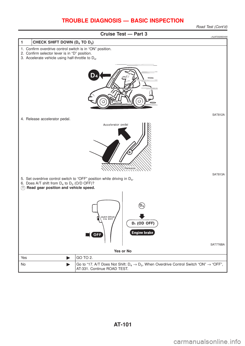
Cruise Test Ð Part 3=NJAT0028S0406
1 CHECK SHIFT DOWN (D4TO D3)
1. Confirm overdrive control switch is in ªONº position.
2. Confirm selector lever is in ªDº position.
3. Accelerate vehicle using half-throttle to D
4.
SAT812A
4. Release accelerator pedal.
SAT813A
5. Set overdrive control switch to ªOFFº position while driving in D4.
6. Does A/T shift from D
4to D3(O/D OFF)?
Read gear position and vehicle speed.
SAT776BA
YesorNo
Ye s©GO TO 2.
No©Go to ª17. A/T Does Not Shift: D
4®D3, When Overdrive Control Switch ªONº®ªOFFº,
AT-331. Continue ROAD TEST.
TROUBLE DIAGNOSIS Ð BASIC INSPECTION
Road Test (Cont'd)
AT-101
Page 104 of 2898
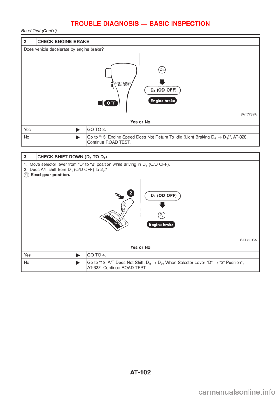
2 CHECK ENGINE BRAKE
Does vehicle decelerate by engine brake?
SAT776BA
YesorNo
Ye s©GO TO 3.
No©Go to ª15. Engine Speed Does Not Return To Idle (Light Braking D
4®D3)º, AT-328.
Continue ROAD TEST.
3 CHECK SHIFT DOWN (D3TO D2)
1. Move selector lever from ªDº to ª2º position while driving in D3(O/D OFF).
2. Does A/T shift from D
3(O/D OFF) to 22?
Read gear position.
SAT791GA
YesorNo
Ye s©GO TO 4.
No©Go to ª18. A/T Does Not Shift: D
3®D2, When Selector Lever ªDº®ª2º Positionº,
AT-332. Continue ROAD TEST.
TROUBLE DIAGNOSIS Ð BASIC INSPECTION
Road Test (Cont'd)
AT-102
Page 105 of 2898
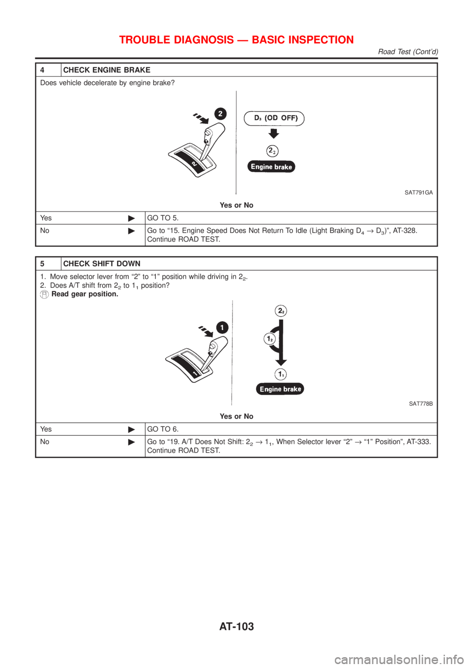
4 CHECK ENGINE BRAKE
Does vehicle decelerate by engine brake?
SAT791GA
YesorNo
Ye s©GO TO 5.
No©Go to ª15. Engine Speed Does Not Return To Idle (Light Braking D
4®D3)º, AT-328.
Continue ROAD TEST.
5 CHECK SHIFT DOWN
1. Move selector lever from ª2º to ª1º position while driving in 22.
2. Does A/T shift from 2
2to 11position?
Read gear position.
SAT778B
YesorNo
Ye s©GO TO 6.
No©Go to ª19. A/T Does Not Shift: 2
2®11, When Selector lever ª2º®ª1º Positionº, AT-333.
Continue ROAD TEST.
TROUBLE DIAGNOSIS Ð BASIC INSPECTION
Road Test (Cont'd)
AT-103
Page 106 of 2898
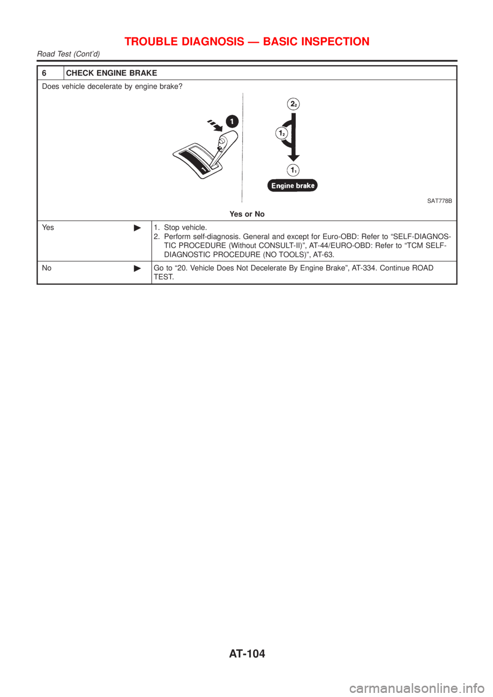
6 CHECK ENGINE BRAKE
Does vehicle decelerate by engine brake?
SAT778B
YesorNo
Ye s©1. Stop vehicle.
2. Perform self-diagnosis. General and except for Euro-OBD: Refer to ªSELF-DIAGNOS-
TIC PROCEDURE (Without CONSULT-II)º, AT-44/EURO-OBD: Refer to ªTCM SELF-
DIAGNOSTIC PROCEDURE (NO TOOLS)º, AT-63.
No©Go to ª20. Vehicle Does Not Decelerate By Engine Brakeº, AT-334. Continue ROAD
TEST.
TROUBLE DIAGNOSIS Ð BASIC INSPECTION
Road Test (Cont'd)
AT-104
Page 126 of 2898
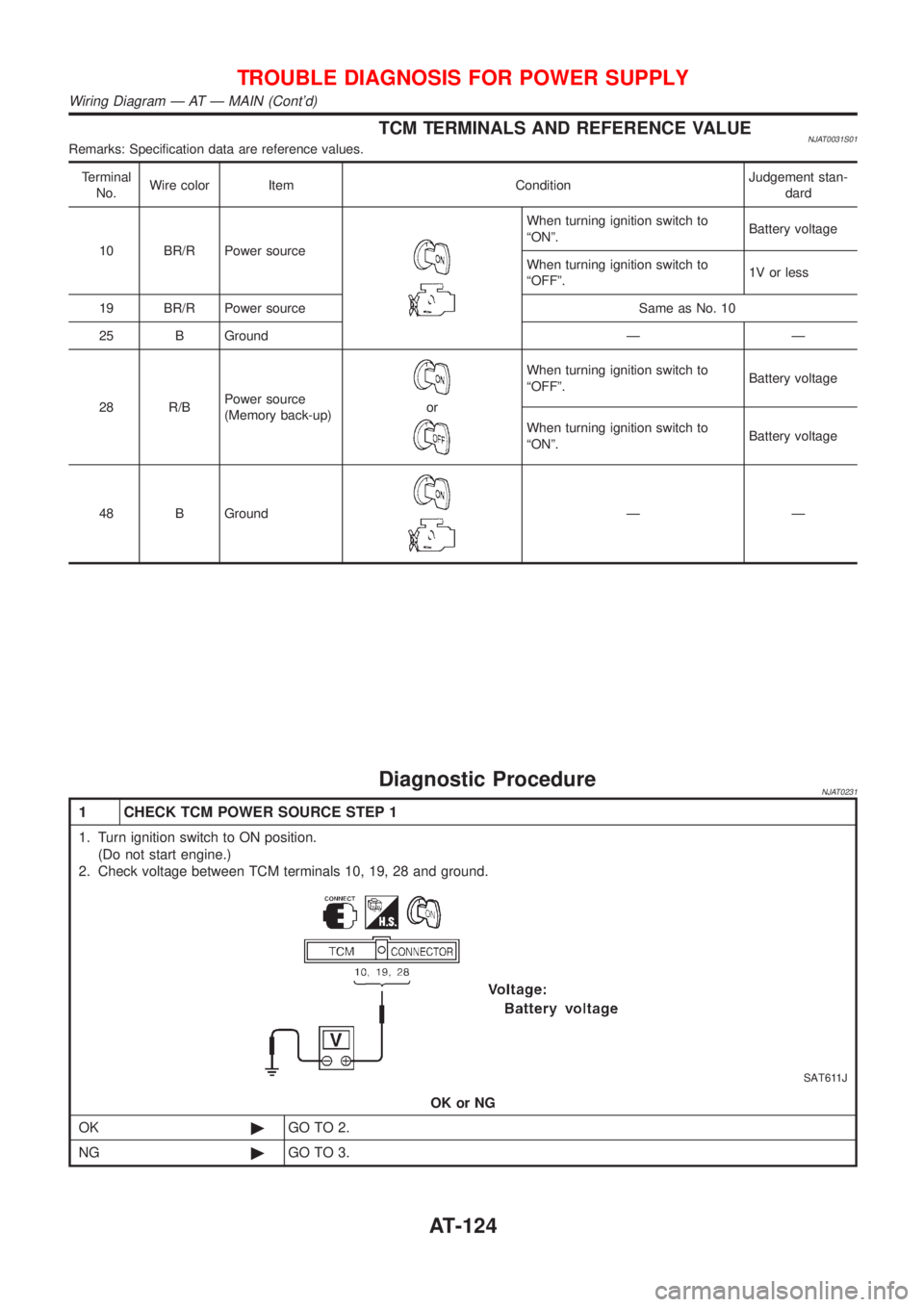
TCM TERMINALS AND REFERENCE VALUENJAT0031S01Remarks: Specification data are reference values.
Terminal
No.Wire color Item ConditionJudgement stan-
dard
10 BR/R Power source
When turning ignition switch to
ªONº.Battery voltage
When turning ignition switch to
ªOFFº.1V or less
19 BR/R Power source Same as No. 10
25 B Ground Ð Ð
28 R/BPower source
(Memory back-up)
or
When turning ignition switch to
ªOFFº.Battery voltage
When turning ignition switch to
ªONº.Battery voltage
48 B Ground
ÐÐ
Diagnostic ProcedureNJAT0231
1 CHECK TCM POWER SOURCE STEP 1
1. Turn ignition switch to ON position.
(Do not start engine.)
2. Check voltage between TCM terminals 10, 19, 28 and ground.
SAT611J
OK or NG
OK©GO TO 2.
NG©GO TO 3.
TROUBLE DIAGNOSIS FOR POWER SUPPLY
Wiring Diagram Ð AT Ð MAIN (Cont'd)
AT-124
Page 127 of 2898
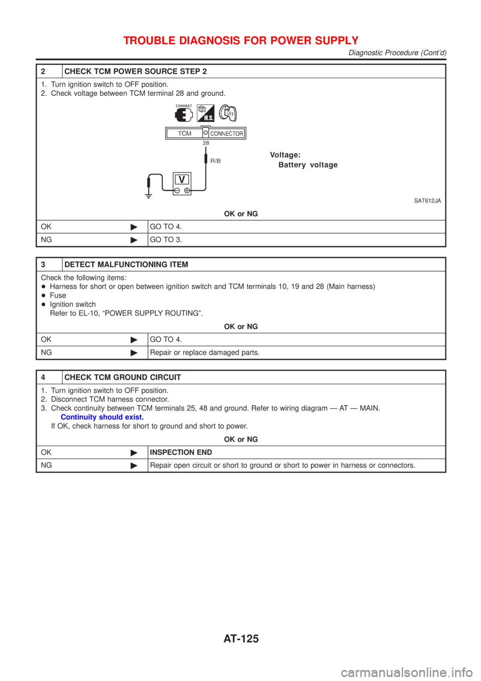
2 CHECK TCM POWER SOURCE STEP 2
1. Turn ignition switch to OFF position.
2. Check voltage between TCM terminal 28 and ground.
SAT612JA
OK or NG
OK©GO TO 4.
NG©GO TO 3.
3 DETECT MALFUNCTIONING ITEM
Check the following items:
+Harness for short or open between ignition switch and TCM terminals 10, 19 and 28 (Main harness)
+Fuse
+Ignition switch
Refer to EL-10, ªPOWER SUPPLY ROUTINGº.
OK or NG
OK©GO TO 4.
NG©Repair or replace damaged parts.
4 CHECK TCM GROUND CIRCUIT
1. Turn ignition switch to OFF position.
2. Disconnect TCM harness connector.
3. Check continuity between TCM terminals 25, 48 and ground. Refer to wiring diagram Ð AT Ð MAIN.
Continuity should exist.
If OK, check harness for short to ground and short to power.
OK or NG
OK©INSPECTION END
NG©Repair open circuit or short to ground or short to power in harness or connectors.
TROUBLE DIAGNOSIS FOR POWER SUPPLY
Diagnostic Procedure (Cont'd)
AT-125
Page 128 of 2898
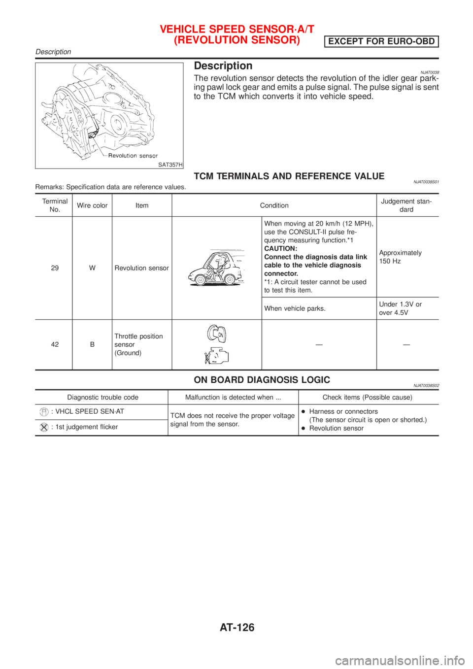
SAT357H
DescriptionNJAT0038The revolution sensor detects the revolution of the idler gear park-
ing pawl lock gear and emits a pulse signal. The pulse signal is sent
to the TCM which converts it into vehicle speed.
TCM TERMINALS AND REFERENCE VALUENJAT0038S01Remarks: Specification data are reference values.
Terminal
No.Wire color Item ConditionJudgement stan-
dard
29 W Revolution sensor
When moving at 20 km/h (12 MPH),
use the CONSULT-II pulse fre-
quency measuring function.*1
CAUTION:
Connect the diagnosis data link
cable to the vehicle diagnosis
connector.
*1: A circuit tester cannot be used
to test this item.Approximately
150 Hz
When vehicle parks.Under 1.3V or
over 4.5V
42 BThrottle position
sensor
(Ground)
ÐÐ
ON BOARD DIAGNOSIS LOGICNJAT0038S02
Diagnostic trouble code Malfunction is detected when ... Check items (Possible cause)
: VHCL SPEED SEN´AT
TCM does not receive the proper voltage
signal from the sensor.+Harness or connectors
(The sensor circuit is open or shorted.)
+Revolution sensor
: 1st judgement flicker
VEHICLE SPEED SENSOR´A/T
(REVOLUTION SENSOR)
EXCEPT FOR EURO-OBD
Description
AT-126
Page 131 of 2898
Diagnostic ProcedureNJAT0039
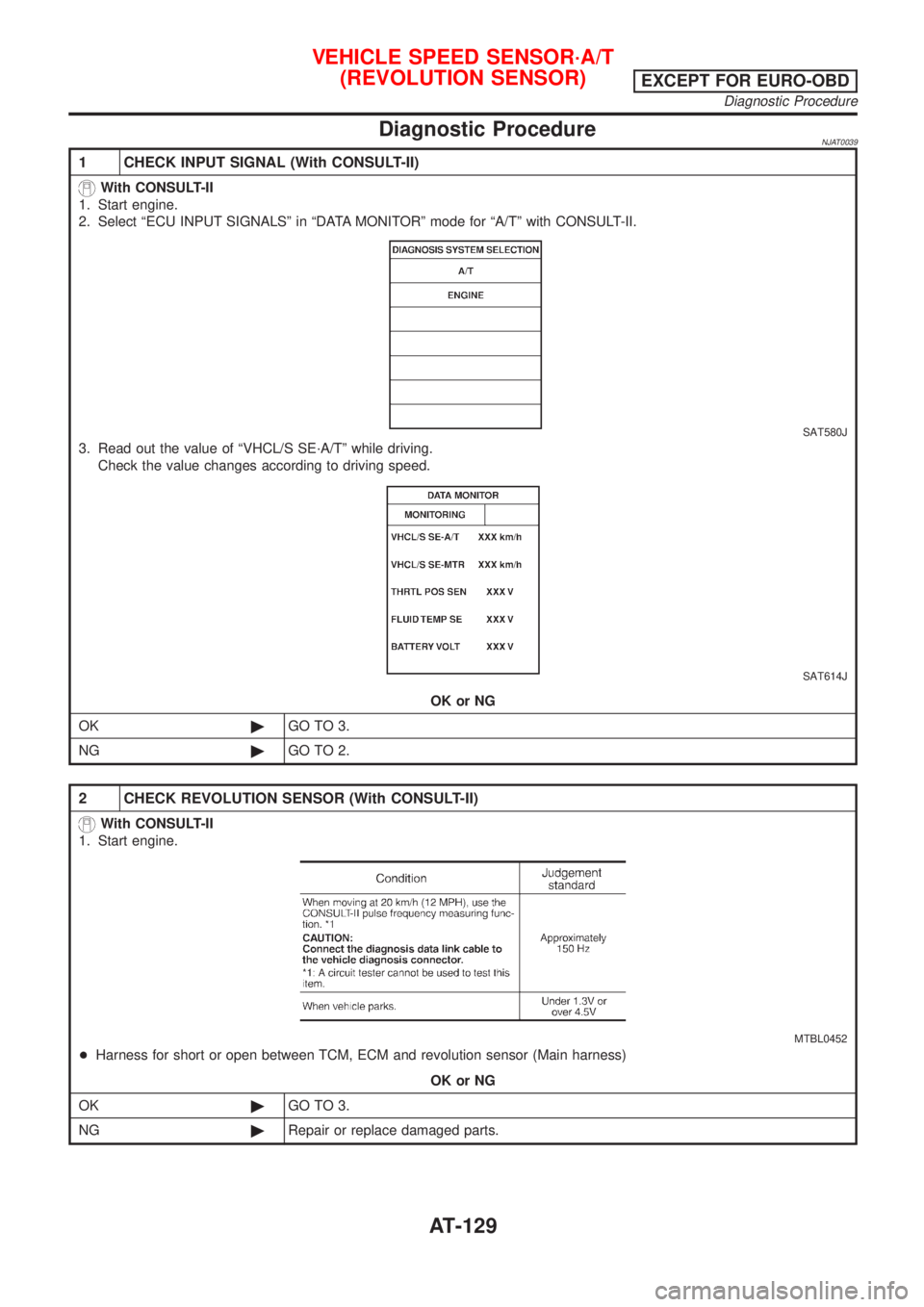
1 CHECK INPUT SIGNAL (With CONSULT-II)
With CONSULT-II
1. Start engine.
2. Select ªECU INPUT SIGNALSº in ªDATA MONITORº mode for ªA/Tº with CONSULT-II.
SAT580J
3. Read out the value of ªVHCL/S SE´A/Tº while driving.
Check the value changes according to driving speed.
SAT614J
OK or NG
OK©GO TO 3.
NG©GO TO 2.
2 CHECK REVOLUTION SENSOR (With CONSULT-II)
With CONSULT-II
1. Start engine.
MTBL0452
+Harness for short or open between TCM, ECM and revolution sensor (Main harness)
OK or NG
OK©GO TO 3.
NG©Repair or replace damaged parts.
VEHICLE SPEED SENSOR´A/T
(REVOLUTION SENSOR)
EXCEPT FOR EURO-OBD
Diagnostic Procedure
AT-129
Page 132 of 2898
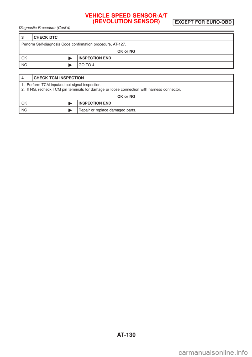
3 CHECK DTC
Perform Self-diagnosis Code confirmation procedure, AT-127.
OK or NG
OK©INSPECTION END
NG©GO TO 4.
4 CHECK TCM INSPECTION
1. Perform TCM input/output signal inspection.
2. If NG, recheck TCM pin terminals for damage or loose connection with harness connector.
OK or NG
OK©INSPECTION END
NG©Repair or replace damaged parts.
VEHICLE SPEED SENSOR´A/T
(REVOLUTION SENSOR)
EXCEPT FOR EURO-OBD
Diagnostic Procedure (Cont'd)
AT-130
Page 133 of 2898
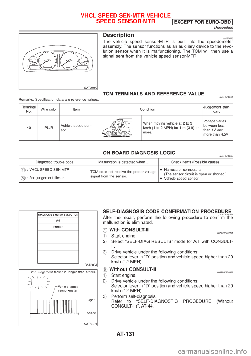
SAT059K
DescriptionNJAT0079The vehicle speed sensor´MTR is built into the speedometer
assembly. The sensor functions as an auxiliary device to the revo-
lution sensor when it is malfunctioning. The TCM will then use a
signal sent from the vehicle speed sensor´MTR.
TCM TERMINALS AND REFERENCE VALUENJAT0079S01Remarks: Specification data are reference values.
Terminal
No.Wire color Item ConditionJudgement stan-
dard
40 PU/RVehicle speed sen-
sor
When moving vehicle at 2 to 3
km/h (1 to 2 MPH) for1m(3ft)or
more.Voltage varies
between less
than 1V and
more than 4.5V
ON BOARD DIAGNOSIS LOGICNJAT0079S02
Diagnostic trouble code Malfunction is detected when ... Check items (Possible cause)
: VHCL SPEED SEN´MTR
TCM does not receive the proper voltage
signal from the sensor.+Harness or connectors
(The sensor circuit is open or shorted.)
+Vehicle speed sensor
: 2nd judgement flicker
SAT580J
SAT807H
SELF-DIAGNOSIS CODE CONFIRMATION PROCEDURENJAT0079S04After the repair, perform the following procedure to confirm the
malfunction is eliminated.
With CONSULT-IINJAT0079S04011) Start engine.
2) Select ªSELF-DIAG RESULTSº mode for A/T with CONSULT-
II.
3) Drive vehicle under the following conditions:
Selector lever in ªDº position and vehicle speed higher than 20
km/h (12 MPH).
Without CONSULT-IINJAT0079S04021) Start engine.
2) Drive vehicle under the following conditions:
Selector lever in ªDº position and vehicle speed higher than 20
km/h (12 MPH).
3) Perform self-diagnosis.
Refer to ªSELF-DIAGNOSTIC PROCEDURE (Without
CONSULT-II)º, AT-44.
VHCL SPEED SEN´MTR VEHICLE
SPEED SENSOR´MTR
EXCEPT FOR EURO-OBD
Description
AT-131