Cylinder head NISSAN ALMERA 2001 Workshop Manual
[x] Cancel search | Manufacturer: NISSAN, Model Year: 2001, Model line: ALMERA, Model: NISSAN ALMERA 2001Pages: 2898, PDF Size: 60.76 MB
Page 2213 of 2898
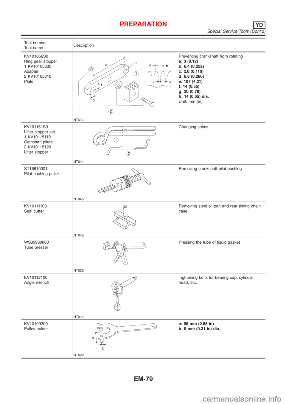
Tool number
Tool nameDescription
KV101056S0
Ring gear stopper
1 KV10105630
Adapter
2 KV10105610
Plate
NT617
Preventing crankshaft from rotating
a: 3 (0.12)
b: 6.4 (0.252)
c: 2.8 (0.110)
d: 6.6 (0.260)
e: 107 (4.21)
f: 14 (0.55)
g: 20 (0.79)
h: 14 (0.55) dia.
Unit: mm (in)
KV101151S0
Lifter stopper set
1 KV10115110
Camshaft pliers
2 KV10115120
Lifter stopper
NT041
Changing shims
ST16610001
Pilot bushing puller
NT045
Removing crankshaft pilot bushing
KV101111 0 0
Seal cutter
NT046
Removing steel oil pan and rear timing chain
case
WS39930000
Tube presser
NT052
Pressing the tube of liquid gasket
KV10112100
Angle wrench
NT014
Tightening bolts for bearing cap, cylinder
head, etc.
KV10109300
Pulley holder
NT628
a: 68 mm (2.68 in)
b: 8 mm (0.31 in) dia.
PREPARATIONYD
Special Service Tools (Cont'd)
EM-79
Page 2216 of 2898
NJEM0051
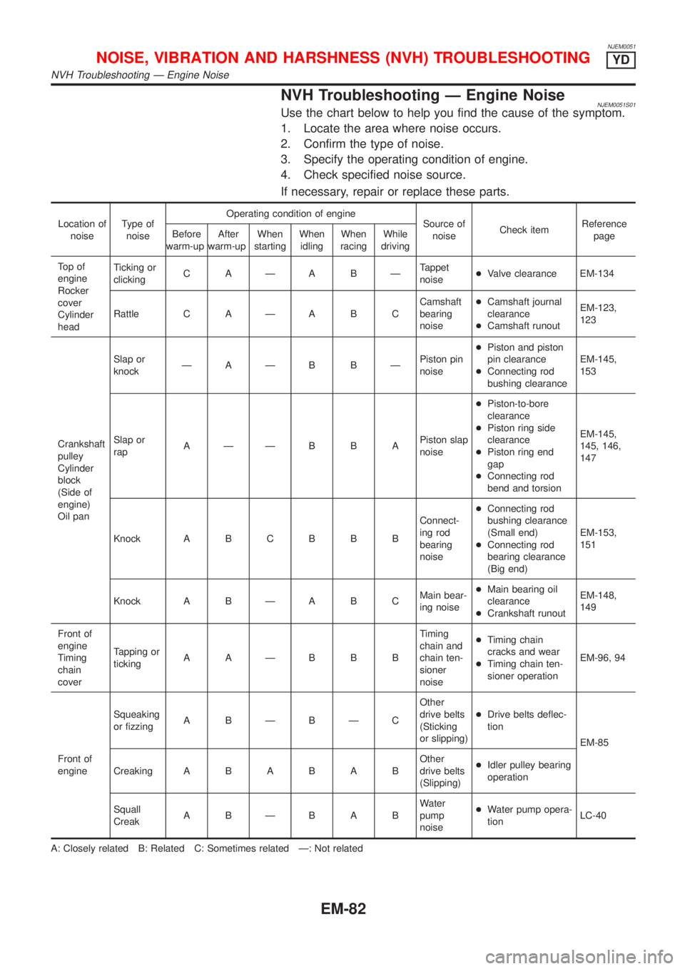
NVH Troubleshooting Ð Engine NoiseNJEM0051S01Use the chart below to help you find the cause of the symptom.
1. Locate the area where noise occurs.
2. Confirm the type of noise.
3. Specify the operating condition of engine.
4. Check specified noise source.
If necessary, repair or replace these parts.
Location of
noiseType of
noiseOperating condition of engine
Source of
noiseCheck itemReference
page Before
warm-upAfter
warm-upWhen
startingWhen
idlingWhen
racingWhile
driving
To p o f
engine
Rocker
cover
Cylinder
headTicking or
clickingC AÐA BÐTappet
noise+Valve clearance EM-134
Rattle C A Ð A B CCamshaft
bearing
noise+Camshaft journal
clearance
+Camshaft runoutEM-123,
123
Crankshaft
pulley
Cylinder
block
(Side of
engine)
Oil panSlap or
knockÐAÐB BÐPiston pin
noise+Piston and piston
pin clearance
+Connecting rod
bushing clearanceEM-145,
153
Slap or
rapAÐÐB B APiston slap
noise+Piston-to-bore
clearance
+Piston ring side
clearance
+Piston ring end
gap
+Connecting rod
bend and torsionEM-145,
145, 146,
147
Knock A B C B B BConnect-
ing rod
bearing
noise+Connecting rod
bushing clearance
(Small end)
+Connecting rod
bearing clearance
(Big end)EM-153,
151
Knock A B Ð A B CMain bear-
ing noise+Main bearing oil
clearance
+Crankshaft runoutEM-148,
149
Front of
engine
Timing
chain
coverTapping or
tickingAAÐBBBTiming
chain and
chain ten-
sioner
noise+Timing chain
cracks and wear
+Timing chain ten-
sioner operationEM-96, 94
Front of
engineSqueaking
or fizzingA BÐBÐCOther
drive belts
(Sticking
or slipping)+Drive belts deflec-
tion
EM-85
CreakingABABABOther
drive belts
(Slipping)+Idler pulley bearing
operation
Squall
CreakABÐBABWater
pump
noise+Water pump opera-
tionLC-40
A: Closely related B: Related C: Sometimes related Ð: Not related
NOISE, VIBRATION AND HARSHNESS (NVH) TROUBLESHOOTINGYD
NVH Troubleshooting Ð Engine Noise
EM-82
Page 2217 of 2898
NJEM0053
JEM111G
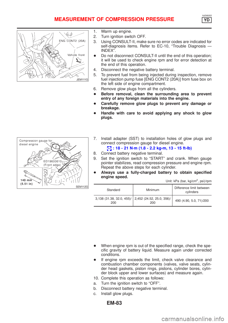
1. Warm up engine.
2. Turn ignition switch OFF.
3. Using CONSULT-II, make sure no error codes are indicated for
self-diagnosis items. Refer to EC-10, ªTrouble Diagnosis Ð
INDEXº.
+Do not disconnect CONSULT-II until the end of this operation;
it will be used to check engine rpm and for error detection at
the end of this operation.
4. Disconnect the negative battery terminal.
5. To prevent fuel from being injected during inspection, remove
fuel injection pump fuse [ENG CONT2 (20A)] from fuse box on
the left side of engine compartment.
6. Remove glow plugs from all the cylinders.
+Before removal, clean the surrounding area to prevent
entry of any foreign materials into the engine.
+Carefully remove glow plugs to prevent any damage or
breakage.
+Handle with care to avoid applying any shock to glow
plugs.
SEM112G
7. Install adapter (SST) to installation holes of glow plugs and
connect compression gauge for diesel engine.
: 18 - 21 N´m (1.8 - 2.2 kg-m, 13 - 15 ft-lb)
8. Connect battery negative terminal.
9. Set the ignition switch to ªSTARTº and crank. When gauge
pointer stabilizes, read compression pressure and engine rpm.
Repeat the above steps for each cylinder.
+Always use a fully-charged battery to obtain specified
engine speed.
Unit: kPa (bar, kg/cm2, psi)/rpm
Standard MinimumDifference limit between
cylinders
3,138 (31.38, 32.0, 455)/
2002,452 (24.52, 25.0, 356)/
200490 (4.90, 5.0, 71)/200
+When engine rpm is out of the specified range, check the spe-
cific gravity of battery liquid. Measure again under corrected
conditions.
+If engine rpm exceeds the limit, check valve clearance and
combustion chamber components (valves, valve seats, cylin-
der head gaskets, piston rings, pistons, cylinder bores, cylin-
der block upper and lower surfaces) and measure again.
10. Complete this operation as follows:
a. Turn the ignition switch to ªOFFº.
b. Disconnect battery negative terminal.
c. Install glow plugs.
MEASUREMENT OF COMPRESSION PRESSUREYD
EM-83
Page 2228 of 2898
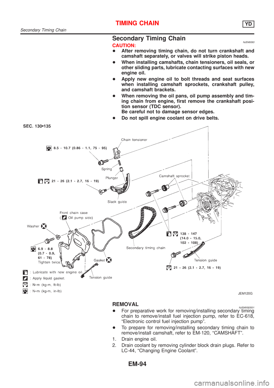
Secondary Timing ChainNJEM0093CAUTION:
+After removing timing chain, do not turn crankshaft and
camshaft separately, or valves will strike piston heads.
+When installing camshafts, chain tensioners, oil seals, or
other sliding parts, lubricate contacting surfaces with new
engine oil.
+Apply new engine oil to bolt threads and seat surfaces
when installing camshaft sprockets, crankshaft pulley,
and camshaft brackets.
+When removing the oil pans, oil pump assembly and tim-
ing chain from engine, first remove the crankshaft posi-
tion sensor (TDC sensor).
Be careful not to damage sensor edges.
+Do not spill engine coolant on drive belts.
JEM120G
REMOVALNJEM0093S01+For preparative work for removing/installing secondary timing
chain to remove/install fuel injection pump, refer to EC-618,
ªElectronic control fuel injection pumpº.
+To prepare for removing/installing secondary timing chain to
remove/install camshaft, refer to EM-120, ªCAMSHAFTº.
1. Drain engine oil.
2. Drain coolant by removing cylinder block drain plugs. Refer to
LC-44, ªChanging Engine Coolantº.
TIMING CHAINYD
Secondary Timing Chain
EM-94
Page 2253 of 2898
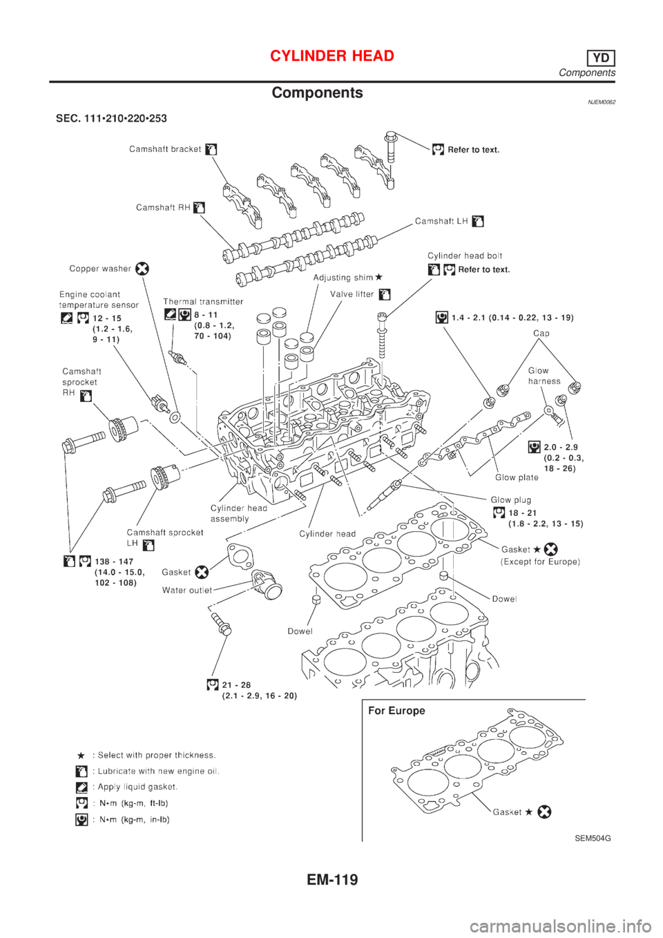
ComponentsNJEM0062
SEM504G
CYLINDER HEADYD
Components
EM-119
Page 2254 of 2898

CAUTION:
+When installing camshafts, chain tensioners, oil seals, or
other sliding parts, lubricate contacting surfaces with new
engine oil.
+Apply new engine oil to threads and seat surfaces when
installing cylinder head, camshaft sprocket, crankshaft
pulley, and camshaft bracket.
+Attach tags to valve lifters so as not to mix them up.
RemovalNJEM0063PREPARATIVE WORKNJEM0063S011. Drain engine coolant. Refer to LC-44, ªChanging Engine Cool-
antº.
2. Remove exhaust manifold. Refer to EM-112, ªRemovalº.
3. Remove intake manifold. Refer to EM-108, ªRemovalº.
+Apply paint to camshaft sprockets for alignment during
installation.
JEM152G
CAMSHAFTNJEM0063S021. Remove the following parts:
+Rocker cover
+Vacuum pump and cylinder head rear cover assembly
+Spill tube
+High pressure injection nozzle assembly
+Secondary timing chain and associated parts
JEM159G
2. Remove camshaft sprockets.
+Holding the hexagonal part of the camshaft with a wrench
having 21 mm (0.83 in) width between facing flats, loosen the
bolt holding the camshaft sprocket.
JEM160G
3. Remove camshafts.
+Loosen bolts holding the camshaft bracket in several stages in
the reverse order of that shown in the figure, and remove them.
4. Remove adjusting shims and valve lifters.
+Confirm the correct location of each part removed. Store them
so they do not get mixed up.
+For re-installation, be sure to put mark on camshaft
bracket before removal.
CYLINDER HEADYD
Components (Cont'd)
EM-120
Page 2255 of 2898
JEM149G
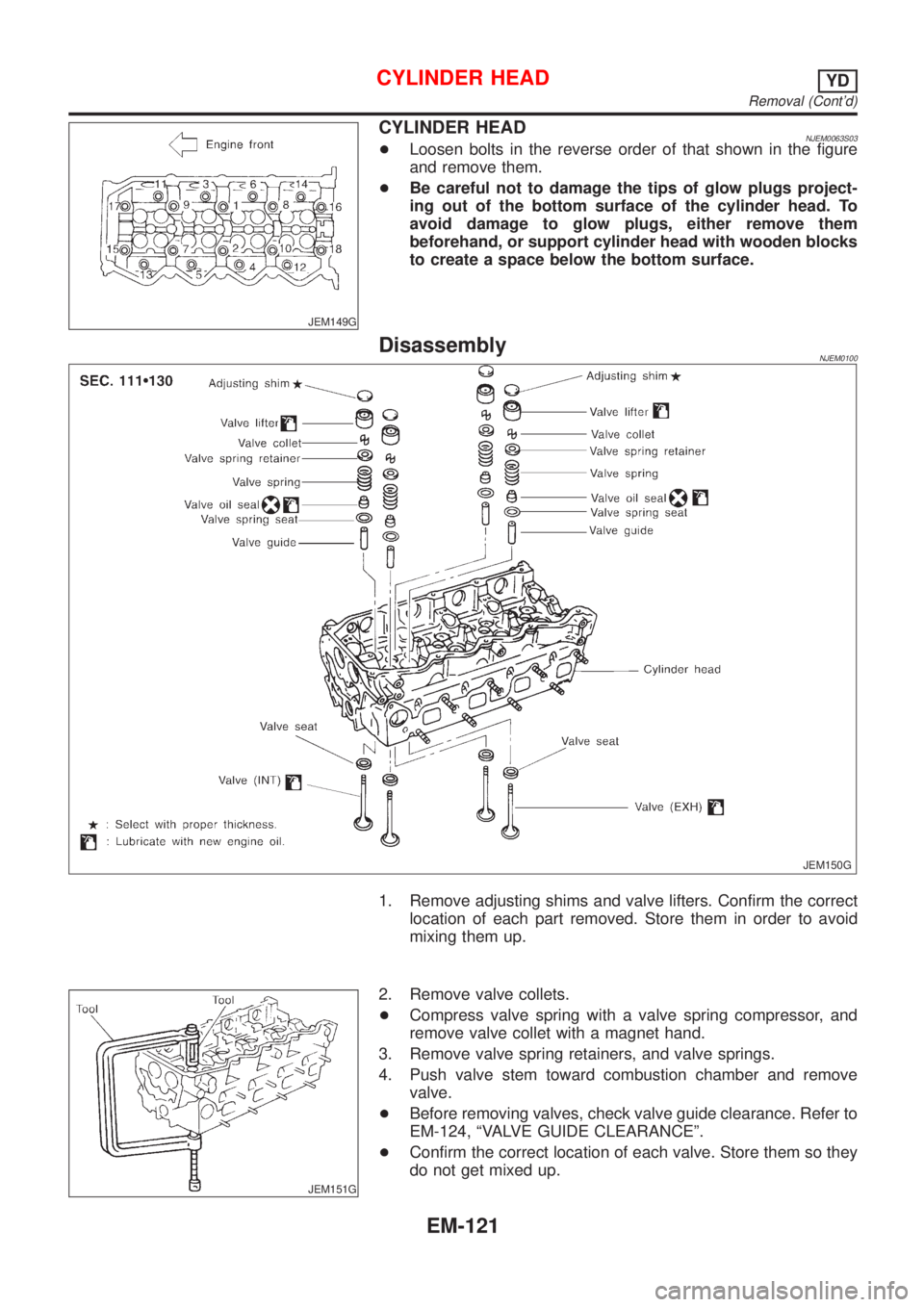
CYLINDER HEADNJEM0063S03+Loosen bolts in the reverse order of that shown in the figure
and remove them.
+Be careful not to damage the tips of glow plugs project-
ing out of the bottom surface of the cylinder head. To
avoid damage to glow plugs, either remove them
beforehand, or support cylinder head with wooden blocks
to create a space below the bottom surface.
DisassemblyNJEM0100
JEM150G
1. Remove adjusting shims and valve lifters. Confirm the correct
location of each part removed. Store them in order to avoid
mixing them up.
JEM151G
2. Remove valve collets.
+Compress valve spring with a valve spring compressor, and
remove valve collet with a magnet hand.
3. Remove valve spring retainers, and valve springs.
4. Push valve stem toward combustion chamber and remove
valve.
+Before removing valves, check valve guide clearance. Refer to
EM-124, ªVALVE GUIDE CLEARANCEº.
+Confirm the correct location of each valve. Store them so they
do not get mixed up.
CYLINDER HEADYD
Removal (Cont'd)
EM-121
Page 2256 of 2898
JEM152G
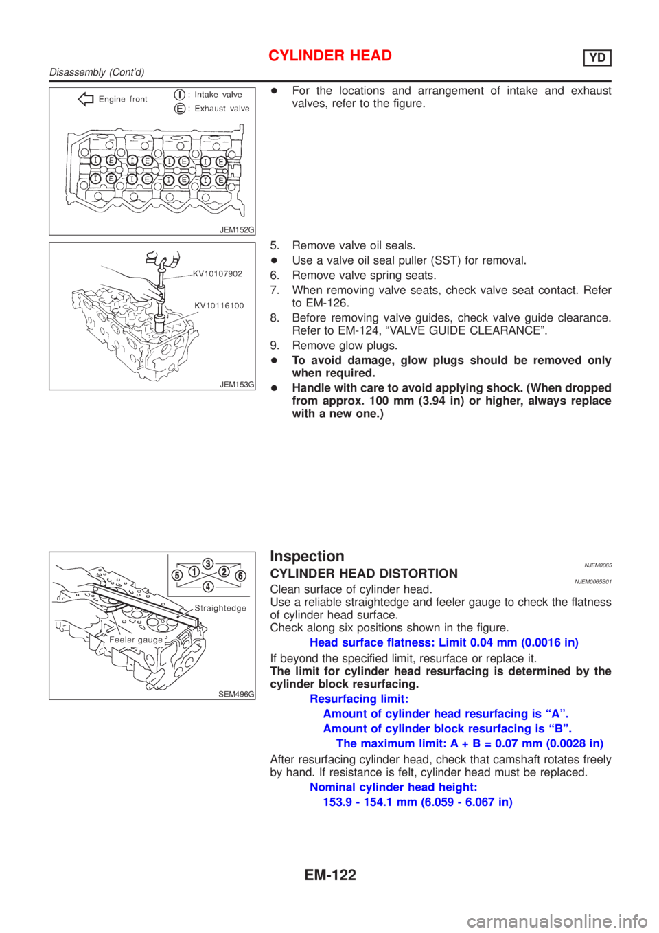
+For the locations and arrangement of intake and exhaust
valves, refer to the figure.
JEM153G
5. Remove valve oil seals.
+Use a valve oil seal puller (SST) for removal.
6. Remove valve spring seats.
7. When removing valve seats, check valve seat contact. Refer
to EM-126.
8. Before removing valve guides, check valve guide clearance.
Refer to EM-124, ªVALVE GUIDE CLEARANCEº.
9. Remove glow plugs.
+To avoid damage, glow plugs should be removed only
when required.
+Handle with care to avoid applying shock. (When dropped
from approx. 100 mm (3.94 in) or higher, always replace
with a new one.)
SEM496G
InspectionNJEM0065CYLINDER HEAD DISTORTIONNJEM0065S01Clean surface of cylinder head.
Use a reliable straightedge and feeler gauge to check the flatness
of cylinder head surface.
Check along six positions shown in the figure.
Head surface flatness: Limit 0.04 mm (0.0016 in)
If beyond the specified limit, resurface or replace it.
The limit for cylinder head resurfacing is determined by the
cylinder block resurfacing.
Resurfacing limit:
Amount of cylinder head resurfacing is ªAº.
Amount of cylinder block resurfacing is ªBº.
The maximum limit: A+ B = 0.07 mm (0.0028 in)
After resurfacing cylinder head, check that camshaft rotates freely
by hand. If resistance is felt, cylinder head must be replaced.
Nominal cylinder head height:
153.9 - 154.1 mm (6.059 - 6.067 in)
CYLINDER HEADYD
Disassembly (Cont'd)
EM-122
Page 2257 of 2898
CAMSHAFT VISUAL CHECKNJEM0065S02Check camshaft for scratches, seizure and wear.
JEM161G
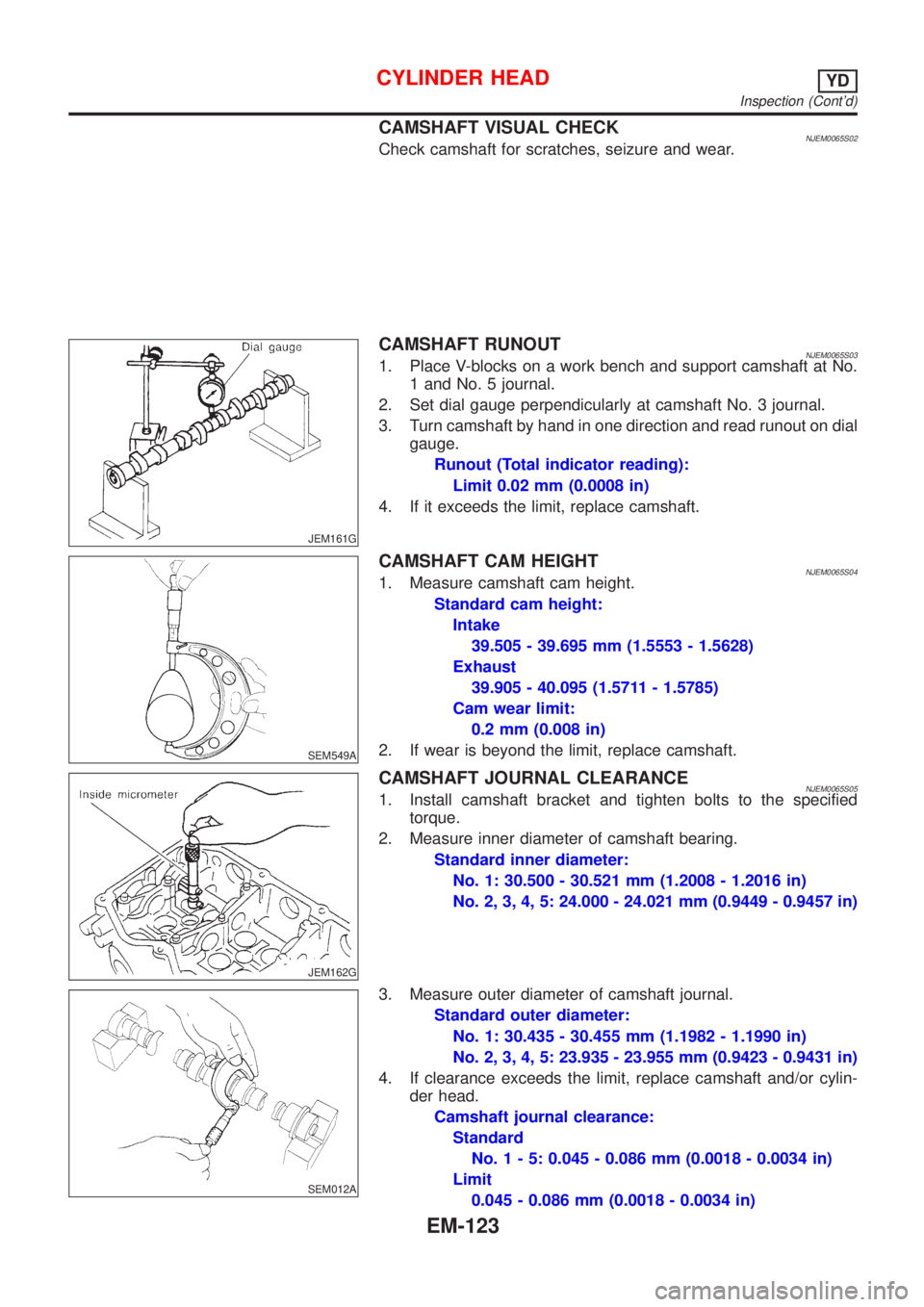
CAMSHAFT RUNOUTNJEM0065S031. Place V-blocks on a work bench and support camshaft at No.
1 and No. 5 journal.
2. Set dial gauge perpendicularly at camshaft No. 3 journal.
3. Turn camshaft by hand in one direction and read runout on dial
gauge.
Runout (Total indicator reading):
Limit 0.02 mm (0.0008 in)
4. If it exceeds the limit, replace camshaft.
SEM549A
CAMSHAFT CAM HEIGHTNJEM0065S041. Measure camshaft cam height.
Standard cam height:
Intake
39.505 - 39.695 mm (1.5553 - 1.5628)
Exhaust
39.905 - 40.095 (1.5711 - 1.5785)
Cam wear limit:
0.2 mm (0.008 in)
2. If wear is beyond the limit, replace camshaft.
JEM162G
CAMSHAFT JOURNAL CLEARANCENJEM0065S051. Install camshaft bracket and tighten bolts to the specified
torque.
2. Measure inner diameter of camshaft bearing.
Standard inner diameter:
No. 1: 30.500 - 30.521 mm (1.2008 - 1.2016 in)
No. 2, 3, 4, 5: 24.000 - 24.021 mm (0.9449 - 0.9457 in)
SEM012A
3. Measure outer diameter of camshaft journal.
Standard outer diameter:
No. 1: 30.435 - 30.455 mm (1.1982 - 1.1990 in)
No. 2, 3, 4, 5: 23.935 - 23.955 mm (0.9423 - 0.9431 in)
4. If clearance exceeds the limit, replace camshaft and/or cylin-
der head.
Camshaft journal clearance:
Standard
No.1-5:0.045 - 0.086 mm (0.0018 - 0.0034 in)
Limit
0.045 - 0.086 mm (0.0018 - 0.0034 in)
CYLINDER HEADYD
Inspection (Cont'd)
EM-123
Page 2258 of 2898
JEM163G
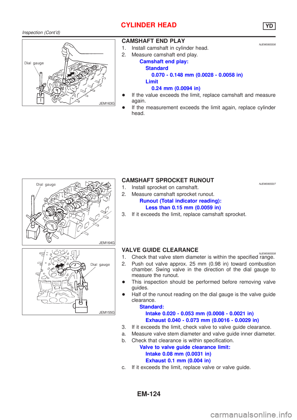
CAMSHAFT END PLAYNJEM0065S061. Install camshaft in cylinder head.
2. Measure camshaft end play.
Camshaft end play:
Standard
0.070 - 0.148 mm (0.0028 - 0.0058 in)
Limit
0.24 mm (0.0094 in)
+If the value exceeds the limit, replace camshaft and measure
again.
+If the measurement exceeds the limit again, replace cylinder
head.
JEM164G
CAMSHAFT SPROCKET RUNOUTNJEM0065S071. Install sprocket on camshaft.
2. Measure camshaft sprocket runout.
Runout (Total indicator reading):
Less than 0.15 mm (0.0059 in)
3. If it exceeds the limit, replace camshaft sprocket.
JEM155G
VALVE GUIDE CLEARANCENJEM0065S081. Check that valve stem diameter is within the specified range.
2. Push out valve approx. 25 mm (0.98 in) toward combustion
chamber. Swing valve in the direction of the dial gauge to
measure the runout.
+This inspection should be performed before removing valve
guides.
+Half of the runout reading on the dial gauge is the valve guide
clearance.
Standard:
Intake 0.020 - 0.053 mm (0.0008 - 0.0021 in)
Exhaust 0.040 - 0.073 mm (0.0016 - 0.0029 in)
3. If it exceeds the limit, check valve to valve guide clearance.
a. Measure valve stem diameter and valve guide inner diameter.
b. Check that clearance is within specification.
Valve to valve guide clearance limit:
Intake 0.08 mm (0.0031 in)
Exhaust 0.1 mm (0.004 in)
c. If it exceeds the limit, replace valve or valve guide.
CYLINDER HEADYD
Inspection (Cont'd)
EM-124