diagram NISSAN ALMERA 2001 Service Manual
[x] Cancel search | Manufacturer: NISSAN, Model Year: 2001, Model line: ALMERA, Model: NISSAN ALMERA 2001Pages: 2898, PDF Size: 60.76 MB
Page 2797 of 2898
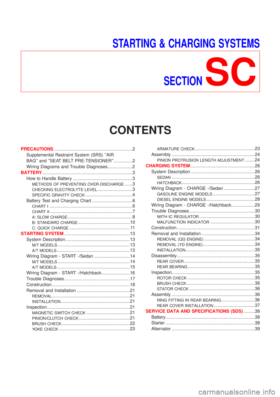
STARTING & CHARGING SYSTEMS
SECTION
SC
CONTENTS
PRECAUTIONS...............................................................2
Supplemental Restraint System (SRS)²AIR
BAG²and²SEAT BELT PRE-TENSIONER²...............2
Wiring Diagrams and Trouble Diagnoses....................2
BATTERY.........................................................................3
How to Handle Battery ................................................3
METHODS OF PREVENTING OVER-DISCHARGE......3
CHECKING ELECTROLYTE LEVEL............................3
SPECIFIC GRAVITY CHECK......................................4
Battery Test and Charging Chart .................................6
CHART I...................................................................6
CHART II..................................................................7
A: SLOW CHARGE....................................................8
B: STANDARD CHARGE..........................................10
C: QUICK CHARGE................................................. 11
STARTING SYSTEM.....................................................13
System Description ....................................................13
M/T MODELS..........................................................13
A/T MODELS...........................................................13
Wiring Diagram - START -/Sedan .............................14
M/T MODELS..........................................................14
A/T MODELS...........................................................15
Wiring Diagram - START -/Hatchback.......................16
Trouble Diagnoses.....................................................17
Construction ...............................................................18
Removal and Installation ...........................................21
REMOVAL...............................................................21
INSTALLATION........................................................21
Inspection...................................................................21
MAGNETIC SWITCH CHECK...................................21
PINION/CLUTCH CHECK.........................................21
BRUSH CHECK.......................................................22
YOKE CHECK.........................................................23
ARMATURE CHECK................................................23
Assembly ...................................................................24
PINION PROTRUSION LENGTH ADJUSTMENT........24
CHARGING SYSTEM....................................................26
System Description ....................................................26
SEDAN...................................................................26
HATCHBACK...........................................................26
Wiring Diagram - CHARGE -/Sedan .........................27
GASOLINE ENGINE MODELS..................................27
DIESEL ENGINE MODELS.......................................28
Wiring Diagram - CHARGE -/Hatchback...................29
Trouble Diagnoses.....................................................30
WITH IC REGULATOR.............................................30
MALFUNCTION INDICATOR....................................30
Construction ...............................................................31
Removal and Installation ...........................................34
REMOVAL (QG ENGINE).........................................34
REMOVAL (YD ENGINE)..........................................34
INSTALLATION........................................................35
Disassembly...............................................................35
REAR COVER.........................................................35
REAR BEARING......................................................35
Inspection...................................................................35
ROTOR CHECK......................................................35
BRUSH CHECK.......................................................36
STATOR CHECK.....................................................36
Assembly ...................................................................36
RING FITTING IN REAR BEARING...........................36
REAR COVER INSTALLATION.................................37
SERVICE DATA AND SPECIFICATIONS (SDS).........38
Battery........................................................................38
Starter ........................................................................38
Alternator ...................................................................39
Page 2798 of 2898
Supplemental Restraint System (SRS) ªAIR
BAGº and ªSEAT BELT PRE-TENSIONERº
NJSC0001The Supplemental Restraint System such as ªAIR BAGº and ªSEAT BELT PRE-TENSIONERº used along with
a seat belt, helps to reduce the risk or severity of injury to the driver and front passenger for certain types of
collision. The SRS system composition which is available to NISSAN MODEL N16 is as follows (The compo-
sition varies according to the destination and optional equipment.):
+For a frontal collision
The Supplemental Restraint System consists of driver air bag module (located in the center of the steer-
ing wheel), front passenger air bag module (located on the instrument panel on passenger side), front seat
belt pre-tensioners, a diagnosis sensor unit, warning lamp, wiring harness and spiral cable.
+For a side collision
The Supplemental Restraint System consists of front side air bag module (located in the outer side of front
seat), side air bag (satellite) sensor, diagnosis sensor unit (one of components of air bags for a frontal
collision), wiring harness, warning lamp (one of components of air bags for a frontal collision).
Information necessary to service the system safely is included in theRS sectionof this Service Manual.
WARNING:
+To avoid rendering the SRS inoperative, which could increase the risk of personal injury or death
in the event of a collision which would result in air bag inflation, all maintenance should be per-
formed by an authorized NISSAN dealer.
+Improper maintenance, including incorrect removal and installation of the SRS, can lead to per-
sonal injury caused by unintentional activation of the system. For removal of Spiral Cable and Air
Bag Module, see the RS section.
+Do not use electrical test equipment on any circuit related to the SRS unless instructed to in this
Service Manual. SRS wiring harnesses can be identified by yellow harness connector.
Wiring Diagrams and Trouble DiagnosesNJSC0002When you read wiring diagrams, refer to the following:
+GI-11, ªHOW TO READ WIRING DIAGRAMSº
+EL-10, ªPOWER SUPPLY ROUTINGº for power distribution circuit
When you perform trouble diagnoses, refer to the following:
+GI-32, ªHOW TO FOLLOW TEST GROUPS IN TROUBLE DIAGNOSESº
+GI-21, ªHOW TO PERFORM EFFICIENT DIAGNOSIS FOR AN ELECTRICAL INCIDENTº
PRECAUTIONS
Supplemental Restraint System (SRS) ªAIR BAGº and ªSEAT BELT PRE-TENSIONERº
SC-2
Page 2810 of 2898
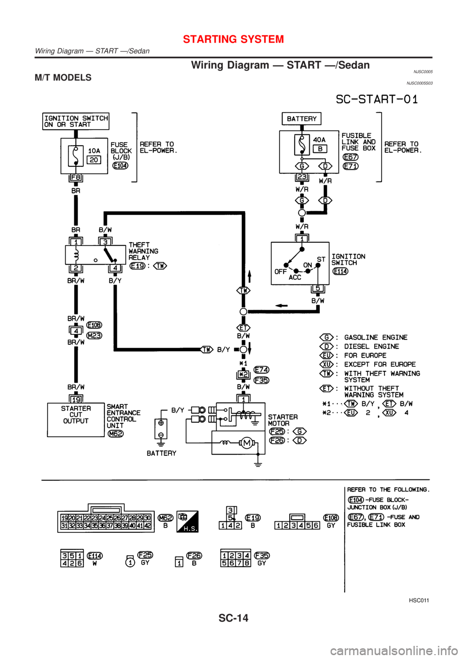
Wiring Diagram Ð START Ð/SedanNJSC0005M/T MODELSNJSC0005S03
HSC011
STARTING SYSTEM
Wiring Diagram Ð START Ð/Sedan
SC-14
Page 2811 of 2898
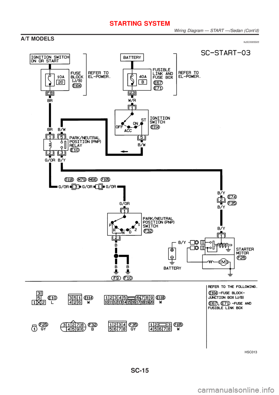
A/T MODELSNJSC0005S05
HSC013
STARTING SYSTEM
Wiring Diagram Ð START Ð/Sedan (Cont'd)
SC-15
Page 2812 of 2898
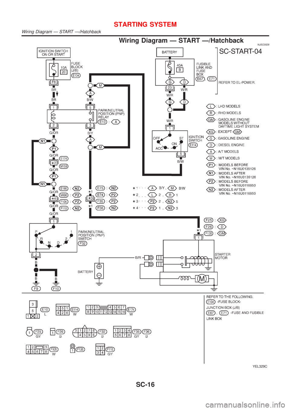
Wiring Diagram Ð START Ð/HatchbackNJSC0028
YEL329C
STARTING SYSTEM
Wiring Diagram Ð START Ð/Hatchback
SC-16
Page 2823 of 2898
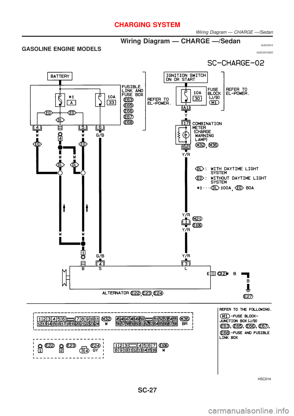
Wiring Diagram Ð CHARGE Ð/SedanNJSC0010GASOLINE ENGINE MODELSNJSC0010S02
HSC014
CHARGING SYSTEM
Wiring Diagram Ð CHARGE Ð/Sedan
SC-27
Page 2824 of 2898
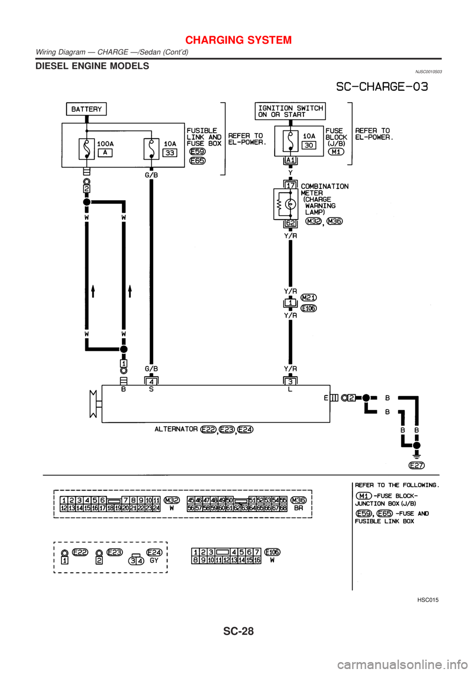
DIESEL ENGINE MODELSNJSC0010S03
HSC015
CHARGING SYSTEM
Wiring Diagram Ð CHARGE Ð/Sedan (Cont'd)
SC-28
Page 2825 of 2898
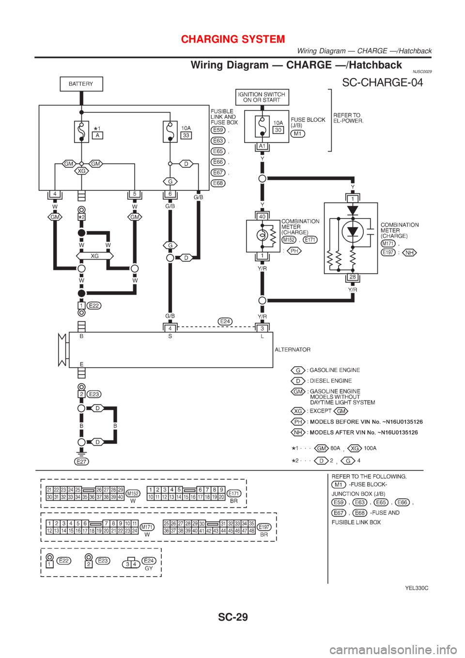
Wiring Diagram Ð CHARGE Ð/HatchbackNJSC0029
YEL330C
CHARGING SYSTEM
Wiring Diagram Ð CHARGE Ð/Hatchback
SC-29