diagram NISSAN ALMERA 2001 Service Manual
[x] Cancel search | Manufacturer: NISSAN, Model Year: 2001, Model line: ALMERA, Model: NISSAN ALMERA 2001Pages: 2898, PDF Size: 60.76 MB
Page 2506 of 2898

Water pump ......................................... LC-14, 39
Water temperature gauge ........................ EL-144
Weatherstrip - See Exterior ....................... BT-47
Wheel alignment (rear) ............................. SU-18
Wheel bearing (front) .................................. AX-3
Wheel bearing (rear) ................................. AX-23
Wheel hub (front) ........................................ AX-5
Wheel hub (rear) ....................................... AX-24
Wheel sensors (ABS) ............................... BR-97
Wheelarch height ........................................ SU-6
Wheelbase (Dimensions) ........................... GI-43
Wide open & closed throttle positionswitch ................................................... EC-207
Width (Dimensions) .................................... GI-43
Window, rear .............................................. BT-71
Windshield ................................................. BT-71
Wiper, front .............................................. EL-215
Wiring diagram (cell code) list ................. EL-575
Wiring diagrams .......................................... GI-11
Withdrawal lever (clutch) ..................... CL-17, 20
Wrist pin -
See Piston pin inspection ............. EM-56, 145
ALPHABETICAL INDEX
IDX-8
Page 2709 of 2898
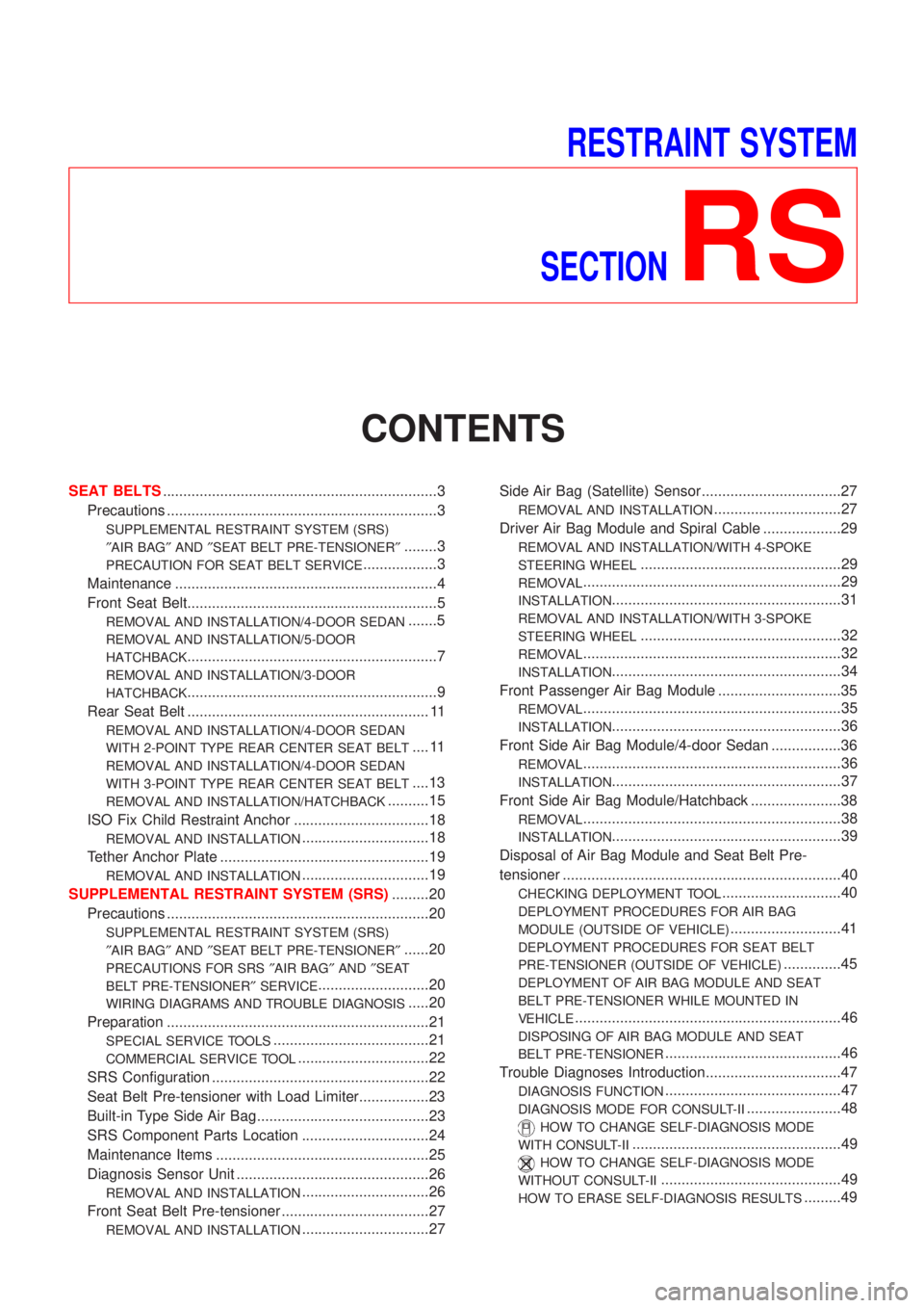
RESTRAINT SYSTEM
SECTION
RS
CONTENTS
SEAT BELTS...................................................................3
Precautions ..................................................................3
SUPPLEMENTAL RESTRAINT SYSTEM (SRS)
²AIR BAG²AND²SEAT BELT PRE-TENSIONER²
........3
PRECAUTION FOR SEAT BELT SERVICE..................3
Maintenance ................................................................4
Front Seat Belt.............................................................5
REMOVAL AND INSTALLATION/4-DOOR SEDAN.......5
REMOVAL AND INSTALLATION/5-DOOR
HATCHBACK
.............................................................7
REMOVAL AND INSTALLATION/3-DOOR
HATCHBACK
.............................................................9
Rear Seat Belt ........................................................... 11
REMOVAL AND INSTALLATION/4-DOOR SEDAN
WITH 2-POINT TYPE REAR CENTER SEAT BELT
.... 11
REMOVAL AND INSTALLATION/4-DOOR SEDAN
WITH 3-POINT TYPE REAR CENTER SEAT BELT
....13
REMOVAL AND INSTALLATION/HATCHBACK..........15
ISO Fix Child Restraint Anchor .................................18
REMOVAL AND INSTALLATION...............................18
Tether Anchor Plate ...................................................19
REMOVAL AND INSTALLATION...............................19
SUPPLEMENTAL RESTRAINT SYSTEM (SRS).........20
Precautions ................................................................20
SUPPLEMENTAL RESTRAINT SYSTEM (SRS)
²AIR BAG²AND²SEAT BELT PRE-TENSIONER²
......20
PRECAUTIONS FOR SRS²AIR BAG²AND²SEAT
BELT PRE-TENSIONER²SERVICE
...........................20
WIRING DIAGRAMS AND TROUBLE DIAGNOSIS.....20
Preparation ................................................................21
SPECIAL SERVICE TOOLS......................................21
COMMERCIAL SERVICE TOOL................................22
SRS Configuration .....................................................22
Seat Belt Pre-tensioner with Load Limiter.................23
Built-in Type Side Air Bag..........................................23
SRS Component Parts Location ...............................24
Maintenance Items ....................................................25
Diagnosis Sensor Unit ...............................................26
REMOVAL AND INSTALLATION...............................26
Front Seat Belt Pre-tensioner ....................................27
REMOVAL AND INSTALLATION...............................27Side Air Bag (Satellite) Sensor ..................................27
REMOVAL AND INSTALLATION...............................27
Driver Air Bag Module and Spiral Cable ...................29
REMOVAL AND INSTALLATION/WITH 4-SPOKE
STEERING WHEEL
.................................................29
REMOVAL...............................................................29
INSTALLATION........................................................31
REMOVAL AND INSTALLATION/WITH 3-SPOKE
STEERING WHEEL
.................................................32
REMOVAL...............................................................32
INSTALLATION........................................................34
Front Passenger Air Bag Module ..............................35
REMOVAL...............................................................35
INSTALLATION........................................................36
Front Side Air Bag Module/4-door Sedan .................36
REMOVAL...............................................................36
INSTALLATION........................................................37
Front Side Air Bag Module/Hatchback ......................38
REMOVAL...............................................................38
INSTALLATION........................................................39
Disposal of Air Bag Module and Seat Belt Pre-
tensioner ....................................................................40
CHECKING DEPLOYMENT TOOL.............................40
DEPLOYMENT PROCEDURES FOR AIR BAG
MODULE (OUTSIDE OF VEHICLE)
...........................41
DEPLOYMENT PROCEDURES FOR SEAT BELT
PRE-TENSIONER (OUTSIDE OF VEHICLE)
..............45
DEPLOYMENT OF AIR BAG MODULE AND SEAT
BELT PRE-TENSIONER WHILE MOUNTED IN
VEHICLE
.................................................................46
DISPOSING OF AIR BAG MODULE AND SEAT
BELT PRE-TENSIONER
...........................................46
Trouble Diagnoses Introduction.................................47
DIAGNOSIS FUNCTION...........................................47
DIAGNOSIS MODE FOR CONSULT-II.......................48
HOW TO CHANGE SELF-DIAGNOSIS MODE
WITH CONSULT-II
...................................................49
HOW TO CHANGE SELF-DIAGNOSIS MODE
WITHOUT CONSULT-II
............................................49
HOW TO ERASE SELF-DIAGNOSIS RESULTS.........49
Page 2710 of 2898
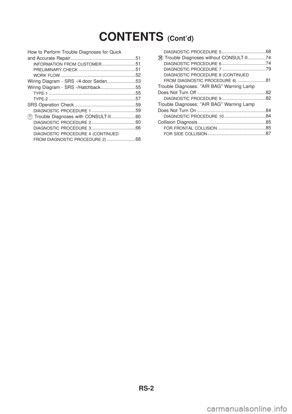
How to Perform Trouble Diagnoses for Quick
and Accurate Repair ..................................................51
INFORMATION FROM CUSTOMER..........................51
PRELIMINARY CHECK............................................51
WORK FLOW..........................................................52
Wiring Diagram - SRS -/4-door Sedan......................53
Wiring Diagram - SRS -/Hatchback...........................55
TYPE-1...................................................................55
TYPE-2...................................................................57
SRS Operation Check ...............................................59
DIAGNOSTIC PROCEDURE 1..................................59
Trouble Diagnoses with CONSULT-II...................60
DIAGNOSTIC PROCEDURE 2..................................60
DIAGNOSTIC PROCEDURE 3..................................66
DIAGNOSTIC PROCEDURE 4 (CONTINUED
FROM DIAGNOSTIC PROCEDURE 2)
......................68
DIAGNOSTIC PROCEDURE 5..................................68
Trouble Diagnoses without CONSULT-II..............74
DIAGNOSTIC PROCEDURE 6..................................74
DIAGNOSTIC PROCEDURE 7..................................79
DIAGNOSTIC PROCEDURE 8 (CONTINUED
FROM DIAGNOSTIC PROCEDURE 6)
......................81
Trouble Diagnoses:²AIR BAG²Warning Lamp
Does Not Turn Off .....................................................82
DIAGNOSTIC PROCEDURE 9..................................82
Trouble Diagnoses:²AIR BAG²Warning Lamp
Does Not Turn On .....................................................84
DIAGNOSTIC PROCEDURE 10................................84
Collision Diagnosis ....................................................85
FOR FRONTAL COLLISION.....................................85
FOR SIDE COLLISION.............................................87
CONTENTS(Cont'd)
RS-2
Page 2728 of 2898
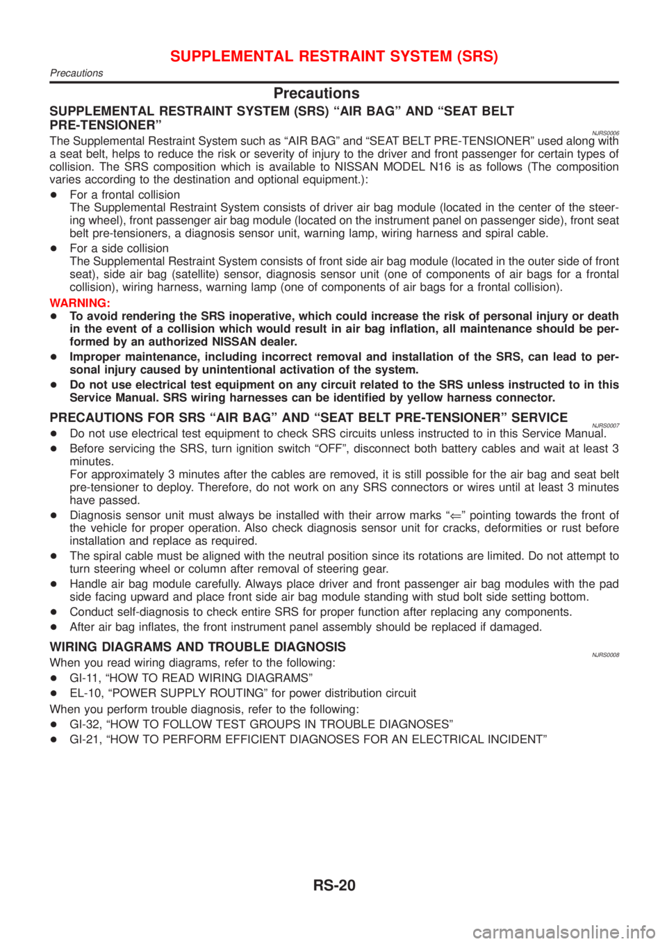
Precautions
SUPPLEMENTAL RESTRAINT SYSTEM (SRS) ªAIR BAGº AND ªSEAT BELT
PRE-TENSIONERº
NJRS0006The Supplemental Restraint System such as ªAIR BAGº and ªSEAT BELT PRE-TENSIONERº used along with
a seat belt, helps to reduce the risk or severity of injury to the driver and front passenger for certain types of
collision. The SRS composition which is available to NISSAN MODEL N16 is as follows (The composition
varies according to the destination and optional equipment.):
+For a frontal collision
The Supplemental Restraint System consists of driver air bag module (located in the center of the steer-
ing wheel), front passenger air bag module (located on the instrument panel on passenger side), front seat
belt pre-tensioners, a diagnosis sensor unit, warning lamp, wiring harness and spiral cable.
+For a side collision
The Supplemental Restraint System consists of front side air bag module (located in the outer side of front
seat), side air bag (satellite) sensor, diagnosis sensor unit (one of components of air bags for a frontal
collision), wiring harness, warning lamp (one of components of air bags for a frontal collision).
WARNING:
+To avoid rendering the SRS inoperative, which could increase the risk of personal injury or death
in the event of a collision which would result in air bag inflation, all maintenance should be per-
formed by an authorized NISSAN dealer.
+Improper maintenance, including incorrect removal and installation of the SRS, can lead to per-
sonal injury caused by unintentional activation of the system.
+Do not use electrical test equipment on any circuit related to the SRS unless instructed to in this
Service Manual. SRS wiring harnesses can be identified by yellow harness connector.
PRECAUTIONS FOR SRS ªAIR BAGº AND ªSEAT BELT PRE-TENSIONERº SERVICENJRS0007+Do not use electrical test equipment to check SRS circuits unless instructed to in this Service Manual.
+Before servicing the SRS, turn ignition switch ªOFFº, disconnect both battery cables and wait at least 3
minutes.
For approximately 3 minutes after the cables are removed, it is still possible for the air bag and seat belt
pre-tensioner to deploy. Therefore, do not work on any SRS connectors or wires until at least 3 minutes
have passed.
+Diagnosis sensor unit must always be installed with their arrow marks ªÜº pointing towards the front of
the vehicle for proper operation. Also check diagnosis sensor unit for cracks, deformities or rust before
installation and replace as required.
+The spiral cable must be aligned with the neutral position since its rotations are limited. Do not attempt to
turn steering wheel or column after removal of steering gear.
+Handle air bag module carefully. Always place driver and front passenger air bag modules with the pad
side facing upward and place front side air bag module standing with stud bolt side setting bottom.
+Conduct self-diagnosis to check entire SRS for proper function after replacing any components.
+After air bag inflates, the front instrument panel assembly should be replaced if damaged.
WIRING DIAGRAMS AND TROUBLE DIAGNOSISNJRS0008When you read wiring diagrams, refer to the following:
+GI-11, ªHOW TO READ WIRING DIAGRAMSº
+EL-10, ªPOWER SUPPLY ROUTINGº for power distribution circuit
When you perform trouble diagnosis, refer to the following:
+GI-32, ªHOW TO FOLLOW TEST GROUPS IN TROUBLE DIAGNOSESº
+GI-21, ªHOW TO PERFORM EFFICIENT DIAGNOSES FOR AN ELECTRICAL INCIDENTº
SUPPLEMENTAL RESTRAINT SYSTEM (SRS)
Precautions
RS-20
Page 2761 of 2898

Wiring Diagram Ð SRS Ð/4-door SedanNJRS0046
HRS060
SUPPLEMENTAL RESTRAINT SYSTEM (SRS)
Wiring Diagram Ð SRS Ð/4-door Sedan
RS-53
Page 2762 of 2898

HRS061
SUPPLEMENTAL RESTRAINT SYSTEM (SRS)
Wiring Diagram Ð SRS Ð/4-door Sedan (Cont'd)
RS-54
Page 2763 of 2898
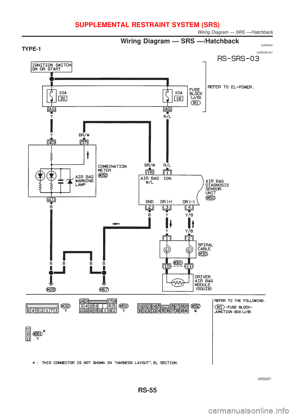
Wiring Diagram Ð SRS Ð/HatchbackNJRS0061TYPE-1NJRS0061S01
HRS057
SUPPLEMENTAL RESTRAINT SYSTEM (SRS)
Wiring Diagram Ð SRS Ð/Hatchback
RS-55
Page 2764 of 2898
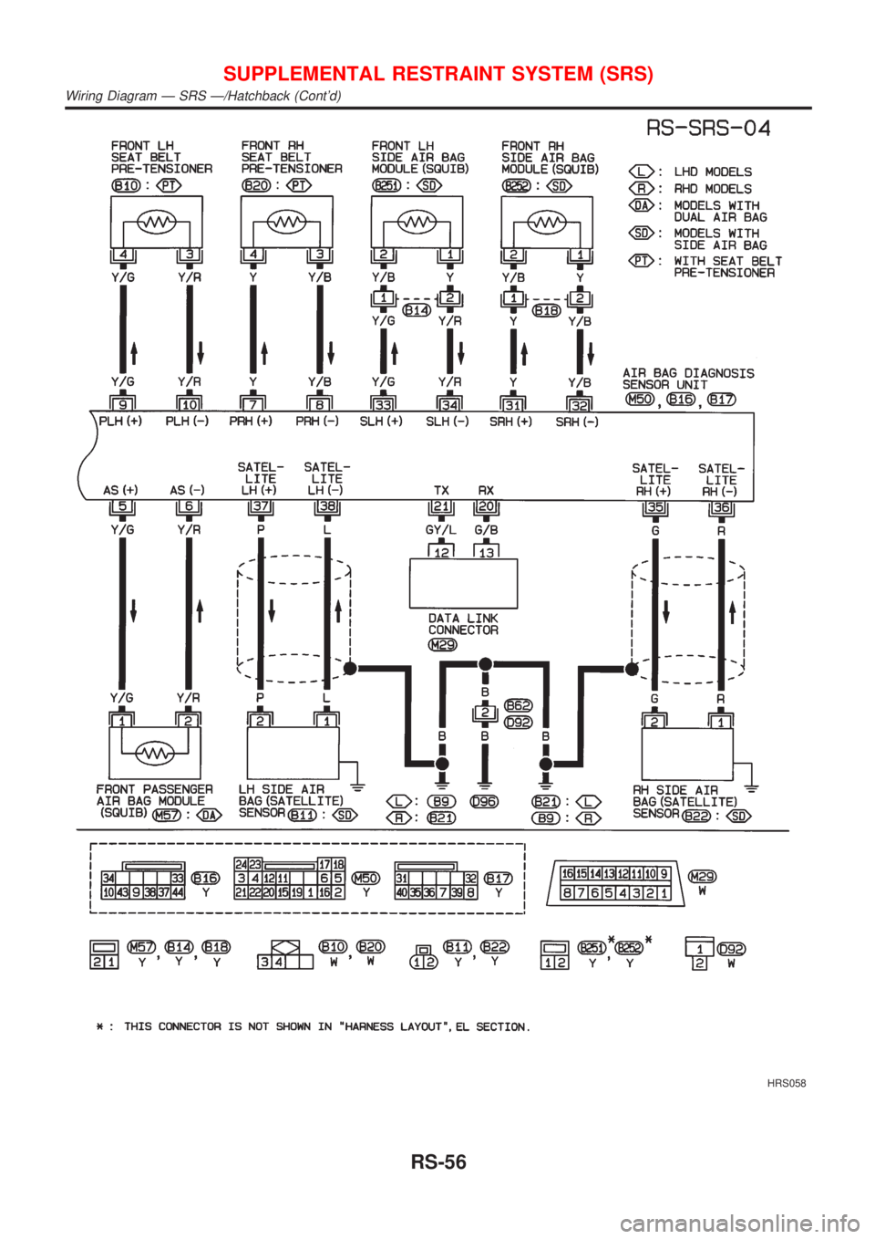
HRS058
SUPPLEMENTAL RESTRAINT SYSTEM (SRS)
Wiring Diagram Ð SRS Ð/Hatchback (Cont'd)
RS-56
Page 2765 of 2898
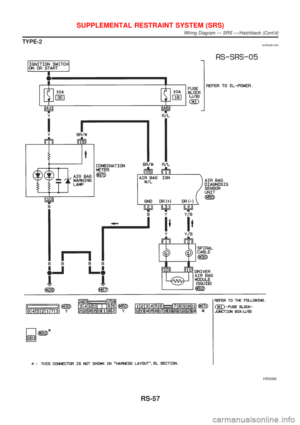
TYPE-2NJRS0061S02
HRS069
SUPPLEMENTAL RESTRAINT SYSTEM (SRS)
Wiring Diagram Ð SRS Ð/Hatchback (Cont'd)
RS-57
Page 2766 of 2898
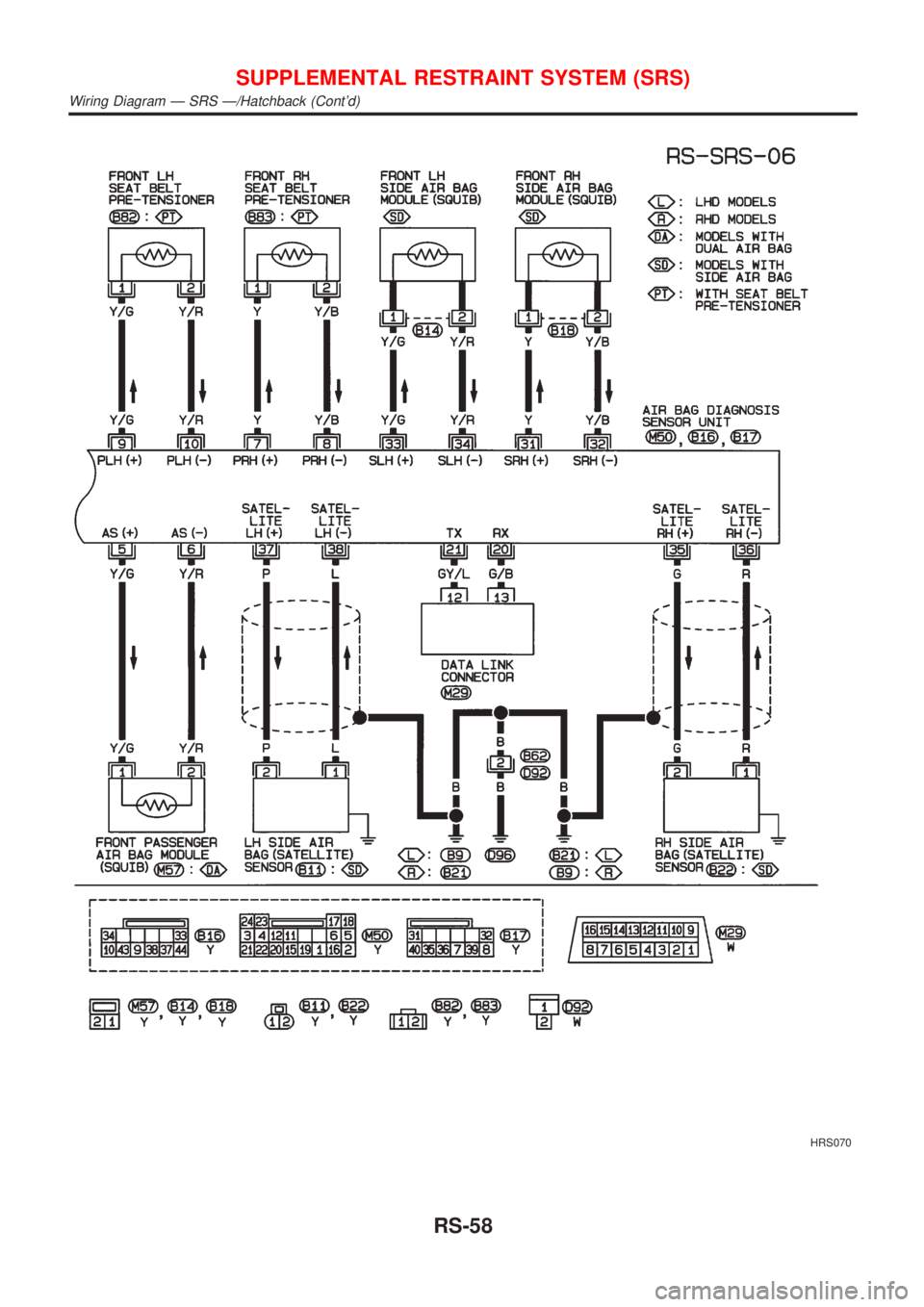
HRS070
SUPPLEMENTAL RESTRAINT SYSTEM (SRS)
Wiring Diagram Ð SRS Ð/Hatchback (Cont'd)
RS-58