Manual trans NISSAN ALMERA N15 1995 User Guide
[x] Cancel search | Manufacturer: NISSAN, Model Year: 1995, Model line: ALMERA N15, Model: NISSAN ALMERA N15 1995Pages: 1701, PDF Size: 82.27 MB
Page 66 of 1701
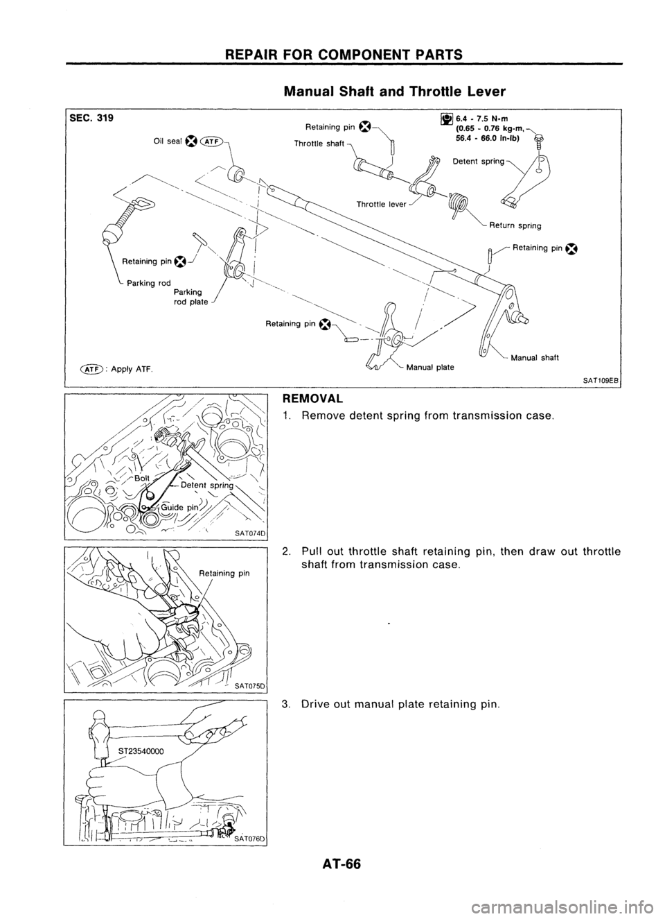
SEC.319
c&D:
ApplyATF. REPAIR
FORCOMPONENT PARTS
Manual ShaftandThrottle Lever
~ 6.4•7.5 N.m
Retaining pm~~ (0.65-0.76 kg-m. "-
Throttle shaft ~ 56.4-66.0 In-Ib)
f
~ 0.""
''''0'''11)
Th""'. ,,~,/ ,
V
~ Return spnng
~ Retaining pin~
)
SAT109EB
REMOVAL
1. Remove detentspringfromtransmission case.
2. Pullout throttleshaftretaining pin,then draw outthrottle
shaft fromtransmission case.
3. Drive outmanual plateretaining pin.
AT-66
Page 67 of 1701

4. Drive andthen pulloutparking rodplate retaining pin.
5. Remove parkingrodplate frommanual shaft.
6. Draw outparking rodfrom trans")
REPAIRFORCOMPONENT PARTS
Manual ShaftandThrottle Lever(ConI'd)
4. Drive andthen pulloutparking rodplate retaining pin.
5. Remove parkingrodplate frommanual shaft.
6. Draw outparking rodfrom transmission case.
7. Pull outmanual shaftretaining pin. •
8. Remove manualshaftandmanual platefromtransmission
i
case.
9. Remove manualshaftoilseal.
SATOBOD
INSPECTION
• Check component partsforwear ordamage. Replaceif
necessary.
AT-67
Page 68 of 1701

INSlALLA liON
1. Install manual shaftoilseal.
• Apply ATFtoouter surface ofoil seal.
2. Install throttle leverandreturn spring")
REPAIRFORCOMPONENT PARTS
Manual ShaftandThrottle Lever(Cont'd)
INSlALLA liON
1. Install manual shaftoilseal.
• Apply ATFtoouter surface ofoil seal.
2. Install throttle leverandreturn spring onthrottle shaft.
3. Install throttle leverassembly ontransmission case.
4. Align groove ofthrottle shaftandhole oftransmission case.
5. Install throttle shaftretaining pin.
6. Move throttle leverinthe direction ofthe arrow.
7. Install manual shaftandmanual plate.
8. Align groove ofmanual shaftandhole oftransmission case.
9. Install manual shaftretaining pin.
AT-68
Page 161 of 1701
'()
Throttle lever'~ ~\
~ Il';-,~\ ,~\\)
,./, Manual plate
2\ (
. ~ -P-' (\
d (
Detent valve
/- \, 'sdJ :----, \,,,
n\ ';\ ~ &")
\~~~~~C0\
~~ \.---.!
~ />"0
o
<=~~ )'()
Throttle lever'~ ~\
~ Il';-,~\ ,~\\)
,./, Manual plate
2\ (
. ~ -P-' (\
d (
Detent valve
/- \, 'sdJ :----, \,,,
n\ ';\ ~ "~
Manualvalve
\3l~w1:
nd\'~~\ \\)~
\(--' "'!f ()~
r:,
A~
\ ~ SAT414D
SAT664D ASSEMBLY
Assembly 4(Conl'd)
b, Set manual shaftinNeutral position.
c. Install control valveassembly ontransmission casewhile
aligning manualvalvewithmanual plateanddetent valve
with throttle lever.
d. Pass solenoid harnessthroughtransmission caseand
install terminal bodyontransmission casebypushing
it.
e. Install cliptoterminal body.
f.
Tighten bolts@,
@. ~
and
@.
Bolt length, number andlocation:
Bolt
@
@ @
@
Bolt length
'T'
mm
(in)
33,0
40,0
43,525,0
(1.299) (1.575)(1,713)
(0.984)
Number ofbolts
652
2
Tightening torque
7-9 (0,7 -0.9, 61-78)
N'm (kg-m, in-Ib)
12. Install oilpan.
a. Attach magnet tooil pan.
AT-161
•
Page 163 of 1701

14. Install inhibitor switch.
a. Set manual shaftin\"P\" position.
b. Temporarily installinhibitor switchonmanual sha")
SAT620E
SAT586H
SAT428DA
Torque
converter
ASSEMBLY
Assembly 4(Cont'd)
14. Install inhibitor switch.
a. Set manual shaftin"P" position.
b. Temporarily installinhibitor switchonmanual shaft.
c.
Move
selector
lever
to"N" position.
d. Use a4mm (0.157 in)pin forthis adjustment.
1) Insert thepinstraight intothemanual shaftadjustment hole.
2) Rotate inhibitor switchuntilthepincan also beinserted
straight intohole ininhibitor switch.
e. Tighten inhibitor switchfixingbolts.
f. Remove pinfrom adjustment holeafter adjusting inhibitor
switch.
15. Install oilcharging pipeandoilcooler tubetotransmission •
case.
16. Install torque converter.
a. Pour ATFintotorque converter.
• Approximately 1liter (7/8Impqt)offluid isrequired fora
new torque converter.
• When reusing oldtorque converter, addthesame amount
of fluid aswas drained.
b. Install torque converter whilealigning notchesoftorque
converter withnotches ofoil pump.
AT-163
Page 1361 of 1701

HOWTOUSE THIS MANUAL
•
•
•
•
•
•
ALPHABETICAL
INDEXisprovided atthe end ofthis manual sothat youcan rapidly findtheitem •
and page youaresearching for.
A QUICK REFERENCE INDEX,ablack tab(e.g.
I=J;J)
is provided onthe first page. Youcanquickly
find thefirst page ofeach section bymating itto the section's blacktab.
THE CONTENTS arelisted onthe first page ofeach section .
THE TITLE isindicated onthe upper portion ofeach pageandshows thepart orsystem .
THE PAGE NUMBER ofeach section consists oftwo letters whichdesignate theparticular section
and anumber (e.g."BR-5").
THE LARGE ILLUSTRATIONS areexploded views(Seebelow) andcontain tightening torques,lubri-
cation points, section number ofthe PARTS CATALOG (e.g.SEC.440) andother information neces-
sary toperform repairs.
The illustrations shouldbeused inreference toservice matters only.When ordering parts,referto
the appropriate PARTSCATALOG.
"Example"
SEC. 440
~~Copper washer
~ /~17-20
<~ ~~
(1.7-2.0, 12•14)
,~
'(~
,
i"::
I
cftJ ~
Brake hose
~ ~Air bleeder
V
1111
7•9 (0.7 -0.9, 61-78)
Pin bolt
~ 22-31 (2.2 -3.2, 16•23)
-Cylinder body~-~
Piston sealm~
Piston
I] ~:
N.m(kg-m, ft-Ib)
It].
N'm(kg-m, in-Ib)
SBR364AC
Outer
shim
Torque
member
Pad
retainer
(Upper side)
1]\
~ jL"J
54... 1'5•'.5, 40•
'71
/~ ~D Mainpin
/ mtosliding portion
o ~
D
~ ~
----------
Pad retainer ~
(Lower Side)m~
• THE SMALL ILLUSTRATIONS showtheimportant steps-suchasinspection, useofspecial tools,
knacks ofwork andhidden ortricky stepswhich arenotshown inthe previous largeillustrations.
Assembly, inspectionandadjustment procedures forthe complicated unitssuchasthe automatic
transaxle ortransmission, etc.arepresented inastep-by-step formatwherenecessary.
GI-7
Page 1362 of 1701

HOWTOUSE THIS MANUAL
ManualTransaxle/Transmission
Automatic Transaxle/
Transmission
Air Conditioner
Power Steering
Special Service Tools
Society ofAutomotive Engineers,
Inc.
Automatic Transmission Fluid
Drive range 1stgear
Drive range 2ndgear
Drive range 3rdgear
Drive range 4thgear
Overdrive
2nd range 2ndgear
2nd range 1stgear
1st range 2ndgear
1st range 1stgear
A/C
PIS
Tool SAE
ATF
0
1
O
2
0
3
0
4
00
2
2
2
1
1
2
1
1
•
The following
SYMBOLS ANDABBREVIATIONS
areused:
to;J,
l\tI
Tightening torque M/T
IE!
Shouldbelubricated withgrease. A/T
Unless otherwise indicated,use
recommended multi-purpose
grease.
Should belubricated withoil.
Sealing point
Checking point
Always replaceafterevery disas-
sembly.
Apply petroleum jelly.
Apply ATF.
Select withproper thickness.
Adjustment isrequired.
Service DataandSpecifications
Left-Hand, Right-Hand
Front, Rear
IE!
~
@
*
1I
SDS LH, RH
FR, RR
• The
UNITS
giveninthis manual areprimarily expressed asthe SlUNIT (International SystemofUnit),
and alternatively expressedinthe metric system andinthe yard/pound system.
"Example" Tightening torque:
59 -78 N'm (6.0-8.0 kg-m, 43-58 ft-Ib)
• TROUBLE DIAGNOSES
areincluded insections dealingwithcomplicated components.
• SERVICE DATAANDSPECIFICATIONS
arecontained atthe end ofeach section forquick reference
of data.
• The captions
WARNING
and
CAUTION
warnyouofsteps thatmust befollowed toprevent personal
injury and/or damage tosome partofthe vehicle.
WARNING
indicatesthepossibility ofpersonal injuryifinstructions arenotfollowed.
CAUTION
indicatesthepossibility ofcomponent damageifinstructions arenotfollowed.
BOLD TYPED STATEMENTS
except
WARNING
and
CAUTION
giveyouhelpful information.
GI-8
Page 1371 of 1701

Use thechart below to'find outwhat each wiring diagram code•
stands for,
Code Section WiringDiagram Name
AACIV ECIACV-AAC
Valve
ABS BR")
HOWTOREAD WIRING DIAGRAMS
Wiring Diagram Codes(CellCodes)
Use thechart below to'find outwhat each wiring diagram code•
stands for,
Code Section WiringDiagram Name
AACIV ECIACV-AAC
Valve
ABS BR
Anti-lock BrakeSystem
A/C HAManualAirConditioner
A/CCUT ECAir
Conditioner CutControl
A/T ATAutomatic Transmission
AIM ELHeadlamp System
AIRREG ECIACV-Air Regulator
AT/C ECA/TControl
AUDIO ELAudio
BACK/L ELBack-up Lamp
CHARGE ELCharging System
CHIME ELWarning Chime
CMPS EC
Camshaft PositionSensor
COOllF ECCooling
FanControl
DEF ELRearWindow Defogger
D/LOCK ELPowerDoorLock
DTRL ELHeadlamp
-With Daytime Light
System
ECTS ECEngine
Coolant Temperature
Sensor
EGR andcanister ControlSolenoid
EGRCIV EC
Valve
FCUT ECFuel
CutSolenoid Valve
F/FOG ELFront
FogLamp
FICO ECIACV-FICD
SolenoidValve
F/PUMP ECFuel
Pump
GLOW ECQuick-glow
system
H/LAMP ELHeadlamp
-Without Daytime
Light System
H/SEAT ELHeated
Seat
HEAT HA
Heater
HLC ELHeadlamp
Washer
H02S ECHeated
Oxygen Sensor
HORN ELHorn,
Cigarette Lighter,Clock
IATS ECIntake
AirTemperature Sensor
IGN/SG ECIgnition
Signal
ILL ELIllumination
INJECT ECInjector
INT/L ELInterior,
SpotandTrunk Room
Lamps Code
Section WiringDiagram Name
KS ECKnock
Sensor
LKUP ECTorque
Converter ClutchSolenoid
Valve
LOAD ECLoadSignal
MAFS ECMass
AirFlow Sensor
MAIN ECMain
Power Supply andGround
Circuit
METER ELSpeedometer,
Tachometer,Temp.
and Fuel Gauges
MIL ECMIL,
Data LinkConnector For
CONSULT
MIRROR ELDOOR
MIRROR
NATS ELNISSAN
ANTI-THEFT SYSTEM
02S ECOXYGEN
SENSOR
EC EVAP
CANISTER PURGECON-
PGCIV TROLSOLENOID VALVE
PLA ECPARTIAL
LOADADVANCE CON-
TROL
EC PARK/NEUTRAL
POSITION
PNP/SW SWITCH
POWER ELPOWER
SUPPLY ROUTING
POWER STEERING OILPRESSURE
PST/SW EC
SWITCH
R/FOG ELREAR
FOGLAMP
SROOF ELSUN
ROOF
SUPPLEMENTAL RESTRAINTSYS-
SRS RS
TEM
S/SIG ECST
ART SIGNAL
START ELSTARTING
SYSTEM
STOP/L ELSTOP
LAMP
TAllIL ELCLEARANCE,
LICENSE,ANDTAIL
LAMPS
TPS ECTHROTTLE
POSITIONSENSOR
TURN SIGNAL ANDHAZARD
TURN EL
WARNING LAMPS
VSS ECVEHICLE
SPEEDSENSOR
VTC ECVTC
SOLENOID VALVE
WARN ELWARNING
LAMPS
WINDOW ELPOWER
WINDOW
WIPER ELFRONT
WIPERANDWASHER
WIP/R ELREAR
WIPER ANDWASHER
GI-17
Page 1372 of 1701

HOWTOPERFORM EFFICIENT DIAGNOSIS FORANELECTRICAL INCIDENT
Work Flow
- - - -- - -- ------ -- - -- STEP 1
--------------------- STEP2
----------------------- STEP3
- - -- ---- - --- - -- --- --- - - --- -- STEP 4
--------- -------------------- STEP5
- - - - ---- -- -- -- -- -- --- --- STEP 6
SGI838
STEP
STEP 1 DESCRIPTION
Get detailed information abouttheconditions andtheenvironment whentheincident occurred.
The following arekey pieces ofinformation requiredtomake agood analysis:
HOW
WHEN
WHAT
WHERE
Vehicle
Model,Engine, Transmission andtheSystem (i.e.Radio).
Date, TimeofDay, Weather Conditions, Frequency.
Road Conditions, AltitudeandTraffic Situation.
System Symptoms, OperatingConditions (OtherComponents Interaction).
Service Historyandifany After Market Accessories havebeen installed.
Operate thesystem, roadtestifnecessary.
Verify theparameter ofthe incident.
If the problem cannotbeduplicated, referto"Incident Simulation Tests"nextpage.
STEP
2
STEP 3Get
theproper diagnosis materialstogetherincluding:
POWER SUPPLY ROUTING
System Operation Descriptions
Applicable ServiceManualSections
Identify wheretobegin diagnosis baseduponyourknowledge ofthe system operation andthecustomer com-
ments.
STEP 4
STEP 5
STEP 6 Inspect
thesystem formechanical binding,looseconnectors orwiring damage.
Determine whichcircuits andcomponents areinvolved anddiagnose usingthePower Supply Routing andHar-
ness Layouts.
Repair orreplace theincident circuitorcomponent.
Operate thesystem inall modes. Verifythesystem worksproperly underallconditions. Makesureyouhave
not inadvertently createdanew incident duringyourdiagnosis orrepair steps.
GI-18
Page 1389 of 1701

Prefix andsuffix designations:
B
AV
A
L
B
FN15
E
G
T
A
T
A: Standard
•
Model E:
RHO models forEurope
G: LHD models forEurope
W: RHO")
IDENTIFICATIONINFORMATION
Model Variation (Cont'd)
Prefix andsuffix designations:
B
AV
A
L
B
FN15
E
G
T
A
T
A: Standard
•
Model E:
RHO models forEurope
G: LHD models forEurope
W: RHO models exceptEurope andAustralia
M: Australia
E: Multiport fuelinjection systemengine
N: Diesel engine
A: 4-speed automatic transaxle
F: 5-speed manualtransaxle
B: L
0: LX or
Q
F: SLX
Q:SR
U: GTI orSSS
L: Left-hand drive
R: Right-hand drive
A: 2-wheel drivemodels
AV: GA14DE engine
AW: GA15DE engine
AY: GA16DE engine
BY: SR20DE engine
VC: CD20 engine
B: 4-door Sedan
F: 5-door Hatchback
E: 3-door Hatchback C:
LX orXI
G: SLX orXIR
GI-35