suspension NISSAN ALMERA N15 1995 Service Manual
[x] Cancel search | Manufacturer: NISSAN, Model Year: 1995, Model line: ALMERA N15, Model: NISSAN ALMERA N15 1995Pages: 1701, PDF Size: 82.27 MB
Page 196 of 1701
__________ BODYALIGNMENT ___________
BODYALIGNMENT _
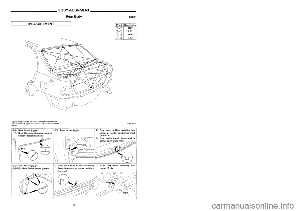
Rear Body Sedan
RearBody 3-door
Hatchback
5-door Hatchback
____ MEASUREMENT _
PointDimension
@~(E)
189*
@~CD
1213*
@~(8)
608*
(E)~@
1110*
~
MEASUREMENT _
Figures marked witha
*
show symmetrically identical
dimensions bothright andleftand lefthand sides ofthe
vehicle.
Unit:
mm
Figures
marked witha
*
show symmetrically identical
dimensions onboth right andlefthand sides ofthe
vehicle.
Unit:
mm
@ :
Rear panel reinforcement back
door lockhole center atcenter
~@ :
Rear suspention installinghole
center (9dia.)
@
:
Rear roofflange endatcenter
(Q@:
Rearfender cornerjoggle
positioning mark
(6)@ :
Rear fender extension joggle
CD :
Rear panel trunklidlock installing
Q):
Rear suspension installinghole
hole flange endatcenter position- center(9dia.)
ing mark
\~
CE)@ :
Rear fender joggle
(8(f)
@@
:
Rear fender joggle
(6)@:
Rear fender joggle
(Q :
Roof flonge positioning markat
center positioning mark
-21-
-24-
Page 197 of 1701

_________ BODYALIGNMENT __________
BODYALIGNMENT _
Passenger Compartment
3-doorHatchback Passenger
Compartment 3-door
Hatchback
Unit: mm
@ :
2nd crossmember standardhole~:Rear suspension installinghole
center atcenter positioning markcenter(9dia.)
(a
dia.)
CDCD :
=:::e~I~~rd~:~)ness installinghole "\\\
}J\ (/ ~
~cp(8
dia.),~
~Yb::~ \\
c?
~~--:q~
,\'I~I~
~~~~ /~FRONT\
- \\\y~ ~ \
____
MEASUREMENT -'
PointDimension
@~
1228
Cf)~
1374
C8},{5)
1094
Q)~
1388
Q)~
1558
(8)~
871
@~@
989*
@--{f)
918*
@~(8)
1193*
@~Q)
1043*
(b)~C8)
1017*
(b)~
655*
Figures marked witha
*
show symmetrically identical
dimensions onboth right andlefthand sides ofthe
vehicle.
Unit:
mm
@ :
Cowl tophole center (5dia.)
(6):
Front roofflange endatcenter
Positioning mark
~@:
}
(B@:
Outerfrontpillar joggle
q:])@ :
Rear fender joggle
CDCD :
Rear fender indention
Q)(D :
Door switch installing holecen-
ter (7dia.) ofnut
(BeD:
}
0
f
"11"d"
~@ :
uter rontpiarIn entlon
@@
:
Dash upper flange endcorner
-23-
-22-
Page 198 of 1701
_________ BODYALIGNMENT __________
BODYALIGNMENT _
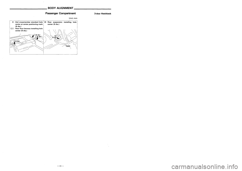
Passenger Compartment
3-doorHatchback Passenger
Compartment 3-door
Hatchback
Unit: mm
@ :
2nd crossmember standardhole~:Rear suspension installinghole
center atcenter positioning markcenter(9dia.)
(a
dia.)
CDCD :
=:::e~I~~rd~:~)ness installinghole "\\\
}J\ (/ ~
~cp(8
dia.),~
~Yb::~ \\
c?
~~--:q~
,\'I~I~
~~~~ /~FRONT\
- \\\y~ ~ \
____
MEASUREMENT -'
PointDimension
@~
1228
Cf)~
1374
C8},{5)
1094
Q)~
1388
Q)~
1558
(8)~
871
@~@
989*
@--{f)
918*
@~(8)
1193*
@~Q)
1043*
(b)~C8)
1017*
(b)~
655*
Figures marked witha
*
show symmetrically identical
dimensions onboth right andlefthand sides ofthe
vehicle.
Unit:
mm
@ :
Cowl tophole center (5dia.)
(6):
Front roofflange endatcenter
Positioning mark
~@:
}
(B@:
Outerfrontpillar joggle
q:])@ :
Rear fender joggle
CDCD :
Rear fender indention
Q)(D :
Door switch installing holecen-
ter (7dia.) ofnut
(BeD:
}
0
f
"11"d"
~@ :
uter rontpiarIn entlon
@@
:
Dash upper flange endcorner
-23-
-22-
Page 199 of 1701
__________ BODYALIGNMENT ___________
BODYALIGNMENT _
Rear Body Sedan
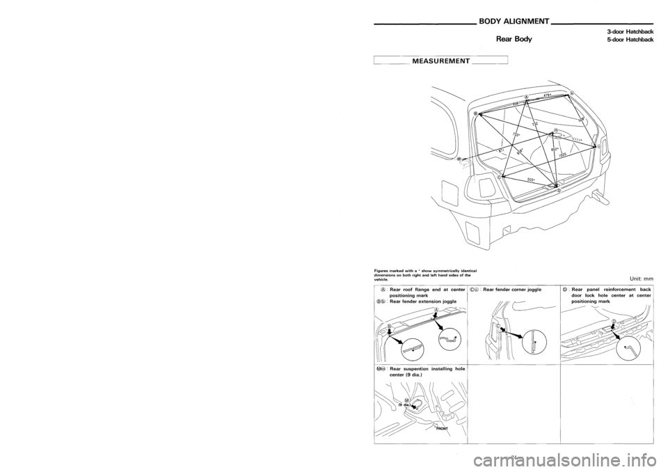
RearBody 3-door
Hatchback
5-door Hatchback
____ MEASUREMENT _
PointDimension
@~(E)
189*
@~CD
1213*
@~(8)
608*
(E)~@
1110*
~
MEASUREMENT _
Figures marked witha
*
show symmetrically identical
dimensions bothright andleftand lefthand sides ofthe
vehicle.
Unit:
mm
Figures
marked witha
*
show symmetrically identical
dimensions onboth right andlefthand sides ofthe
vehicle.
Unit:
mm
@ :
Rear panel reinforcement back
door lockhole center atcenter
~@ :
Rear suspention installinghole
center (9dia.)
@
:
Rear roofflange endatcenter
(Q@:
Rearfender cornerjoggle
positioning mark
(6)@ :
Rear fender extension joggle
CD :
Rear panel trunklidlock installing
Q):
Rear suspension installinghole
hole flange endatcenter position- center(9dia.)
ing mark
\~
CE)@ :
Rear fender joggle
(8(f)
@@
:
Rear fender joggle
(6)@:
Rear fender joggle
(Q :
Roof flonge positioning markat
center positioning mark
-21-
-24-
Page 683 of 1701
FRONTAXLE
&
FRONT SUSPENSION
SECTION
FA
CONTENTS
PRECAUTIONS ANDPREPARATION 2
Precautions 2
Special ServiceTools 2
Commercial ServiceTools 3
FRONT SUSPENSION SySTEM 4
ON-VEHICLE SERVICE
5
Front AxleandFront Suspension Parts 5
Front Wheel Bearing 5
Front Wheel Alignment.. 6
Drive Shaft 7FRONT
AXLE 8
Wheel HubandKnuckle 8
Drive Shaft 12
FRONT SUSPENSION 24
Coil Spring andStrut Assembly 25
Stabilizer Bar 26
Transverse LinkandLower BallJoint.. 27•
SERVICE DATAANDSPECIFICATIONS (SDS)29
General Specifications 29
Inspection andAdjustment 29
Page 684 of 1701
PRECAUTIONSANDPREPARATION
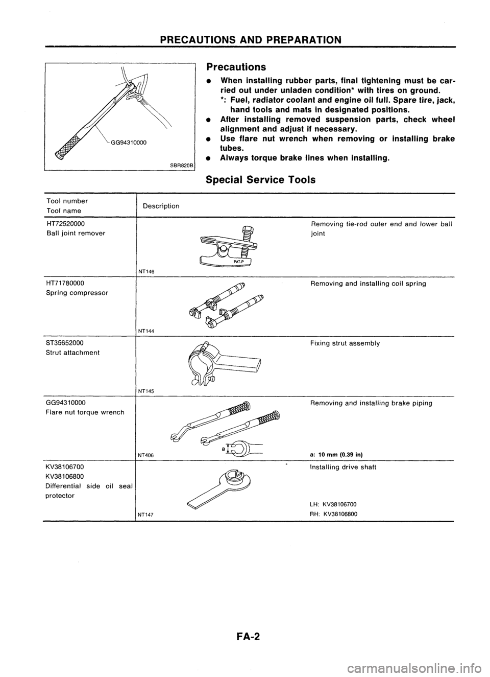
Precautions
• When installing rubberparts,finaltightening mustbecar-
ried outunder unladen condition* withtires onground.
*: Fuel, radiator coolantandengine oilfull. Spare tire,
jack,
hand tools andmats indesignated positions.
• After installing removedsuspension parts,check wheel
alignment andadjust ifnecessary.
• Use flare nutwrench whenremoving orinstalling brake
tubes.
• Always torquebrakelineswhen installing.
Tool number
Tool name
SBR820B
Special Service Tools
Description
HT72520000
Ball joint remover Removing
tie-rodouterendandlower ball
joint
NT146
HT71780000
Spring compressor
ST35652000
Strut attachment
NT144
Removing
andinstalling coilspring
Fixing strutassembly
NT145
GG94310000
Flare nuttorque wrench
KV38106700
KV381 06800
Differential sideoilseal
protector
NT406
NT147
FA-2
Removing
andinstalling brakepiping
a:
10mm (0.39 in)
Installing driveshaft
LH: KV38106700
RH: KV38106800
Page 686 of 1701
FRONTSUSPENSION SYSTEM
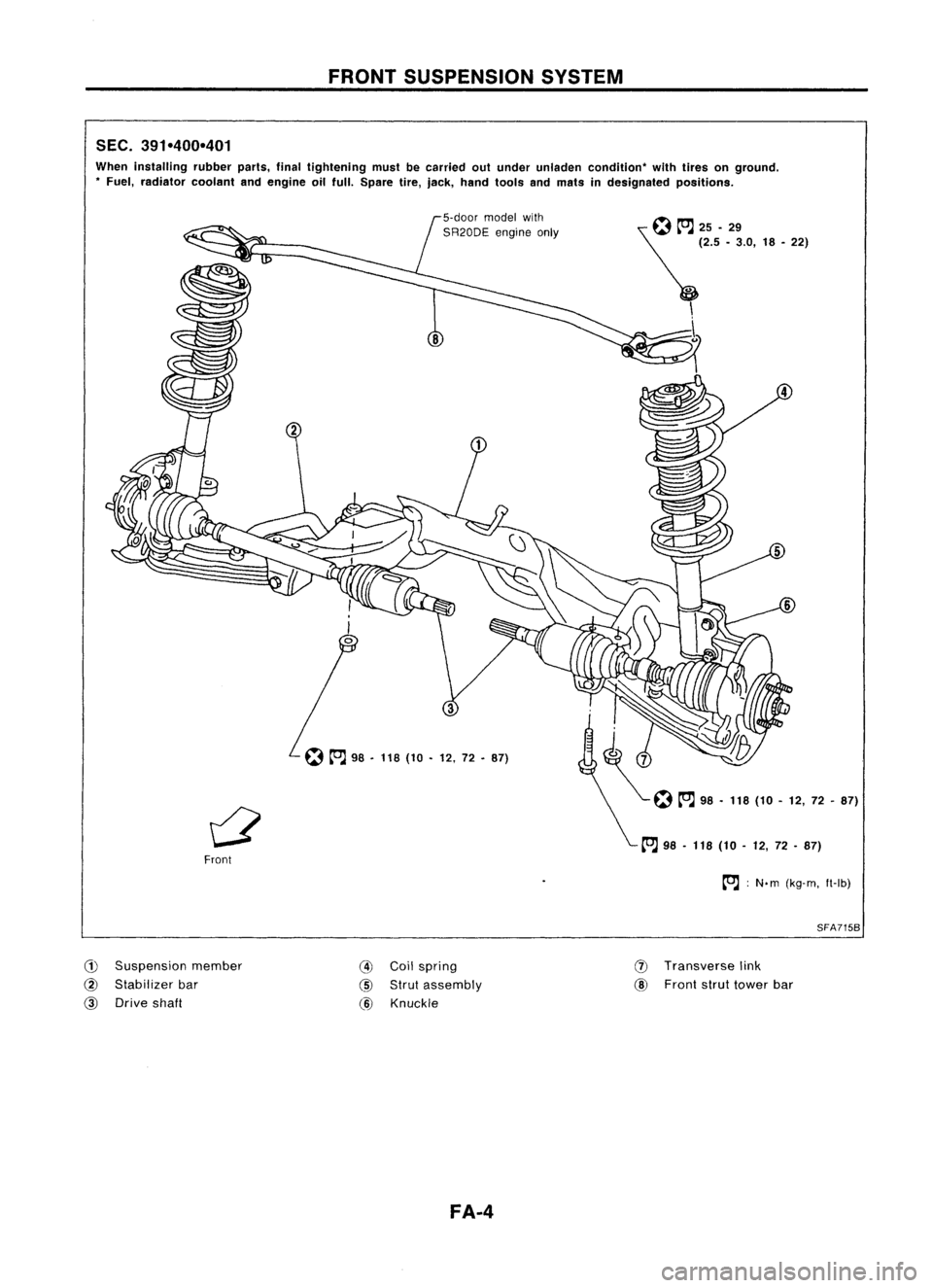
SEC. 391-400-401
When installing rubberparts,finaltightening mustbecarried outunder unladen condition" withtires onground .
• Fuel, radiator coolantandengine oilfull. Spare tire,jack, hand tools andmats indesignated positions.
~~25.29
~ (2.5•3.0, 18•22)
\ \
...
5
~ 98•118 (10•12, 72•87)
Front
to.J:
N. m (kg-m, ft-Ib)
SFA715B
CD
Suspension member
@
Stabilizer bar
@
Drive shaft
@
Coilspring
@
Strut assembly
@
Knuckle
FA-4
(J)
Transverse link
@
Front struttower bar
Page 687 of 1701
SMA525AON-VEHICLE
SERVICE
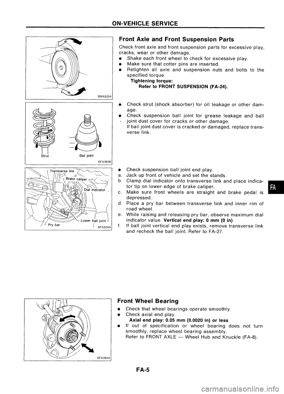
Front AxleandFront Suspension Parts
Check frontaxleandfront suspension partsforexcessive play,
cracks, wearorother damage.
• Shake eachfrontwheel tocheck forexcessive play.
• Make surethatcotter pinsareinserted.
• Retighten allaxle andsuspension nutsandbolts tothe
specified torque.
Tightening torque:
Refer toFRONT SUSPENSION (FA-24).
Strut
Ball
joint
SFA392B
•
Check strut(shock absorber) foroilleakage orother dam-
age.
• Check suspension balljoint forgrease leakage andball
joint dustcover forcracks orother damage.
If ball joint dustcover iscracked ordamaged, replacetrans-
verse link.
• Check suspension balljoint endplay.
a. Jack upfront ofvehicle andsetthe stands.
b. Clamp dialindicator ontotransverse linkand place indica- •
tor tiponlower edgeofbrake caliper. •
c. Make surefront wheels arestraight andbrake pedalis
depressed.
d. Place apry bar between transverse linkand inner rimof
road wheel.
e. While raising andreleasing prybar, observe maximum dial
indicator value.
Vertical endplay: 0mm (0in)
f. Ifball joint vertical endplay exists, remove transverse link
and recheck theball joint. Refer toFA-27.
SFA484A Front
Wheel Bearing
• Check thatwheel bearings operatesmoothly.
• Check axialendplay.
Axial endplay: 0.05mm(0.0020 in)orless
• If
out ofspecification orwheel bearing doesnotturn
smoothly, replacewheelbearing assembly.
Refer toFRONT AXLE-Wheel HubandKnuckle (FA-B).
FA-5
Page 688 of 1701
ON-VEHICLESERVICE
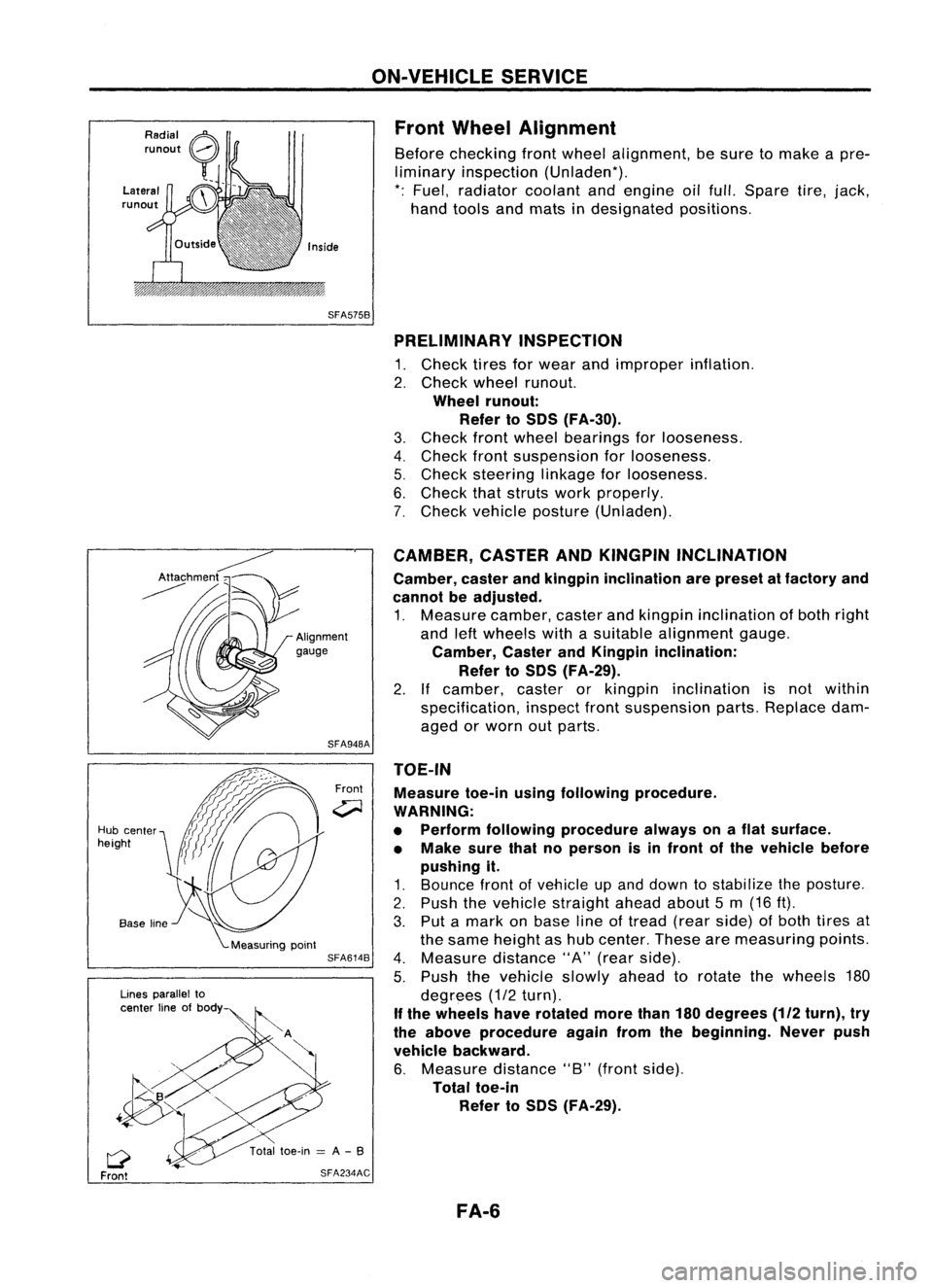
Front Wheel Alignment
Before checking frontwheel alignment, besure tomake apre-
liminary inspection (Unladen*).
*: Fuel, radiator coolantandengine oilfull. Spare tire,jack,
hand tools andmats indesignated positions.
SFA575B PRELIMINARY INSPECTION
1. Check tiresforwear andimproper inflation.
2. Check wheelrunout.
Wheel runout:
Refer toSOS (FA-30).
3. Check frontwheel bearings forlooseness.
4. Check frontsuspension forlooseness.
5. Check steering linkageforlooseness.
6. Check thatstruts workproperly.
7. Check vehicle posture (Unladen).
TOE-IN Measure toe-inusingfollowing procedure.
WARNING:
• Perform following procedure alwaysonaflat surface.
• Make surethatnoperson isin front ofthe vehicle before
pushing it.
1. Bounce frontofvehicle upand down tostabilize theposture.
2. Push thevehicle straight aheadabout5m (16 ft).
3. Put amark onbase lineoftread (rearside) ofboth tires at
the same height ashub center. Thesearemeasuring points.
4. Measure distance"A"(rear side).
5. Push thevehicle slowlyaheadtorotate thewheels 180
degrees (1/2turn).
If the wheels haverotated morethan180degrees
(112
turn), try
the above procedure againfromthebeginning. Neverpush
vehicle backward.
6. Measure distance"B"(front side).
Total toe-in
Refer toSOS (FA-29).
CAMBER,
CASTERANDKINGPIN INCLINATION
Camber, casterandkingpin inclination arepreset atfactory and
cannot beadjusted.
1. Measure camber,casterandkingpin inclination ofboth right
and leftwheels withasuitable alignment gauge.
Camber, CasterandKingpin inclination:
Refer toSOS (FA-29).
2. Ifcamber, casterorkingpin inclination isnot within
specification, inspectfrontsuspension parts.Replace dam-
aged orworn outparts.
Front
SFA948A
SFA614B
SFA234AC
Lines
parallel to
center lineofbody
Q
Front
Hub
center
height
FA-6
Page 706 of 1701
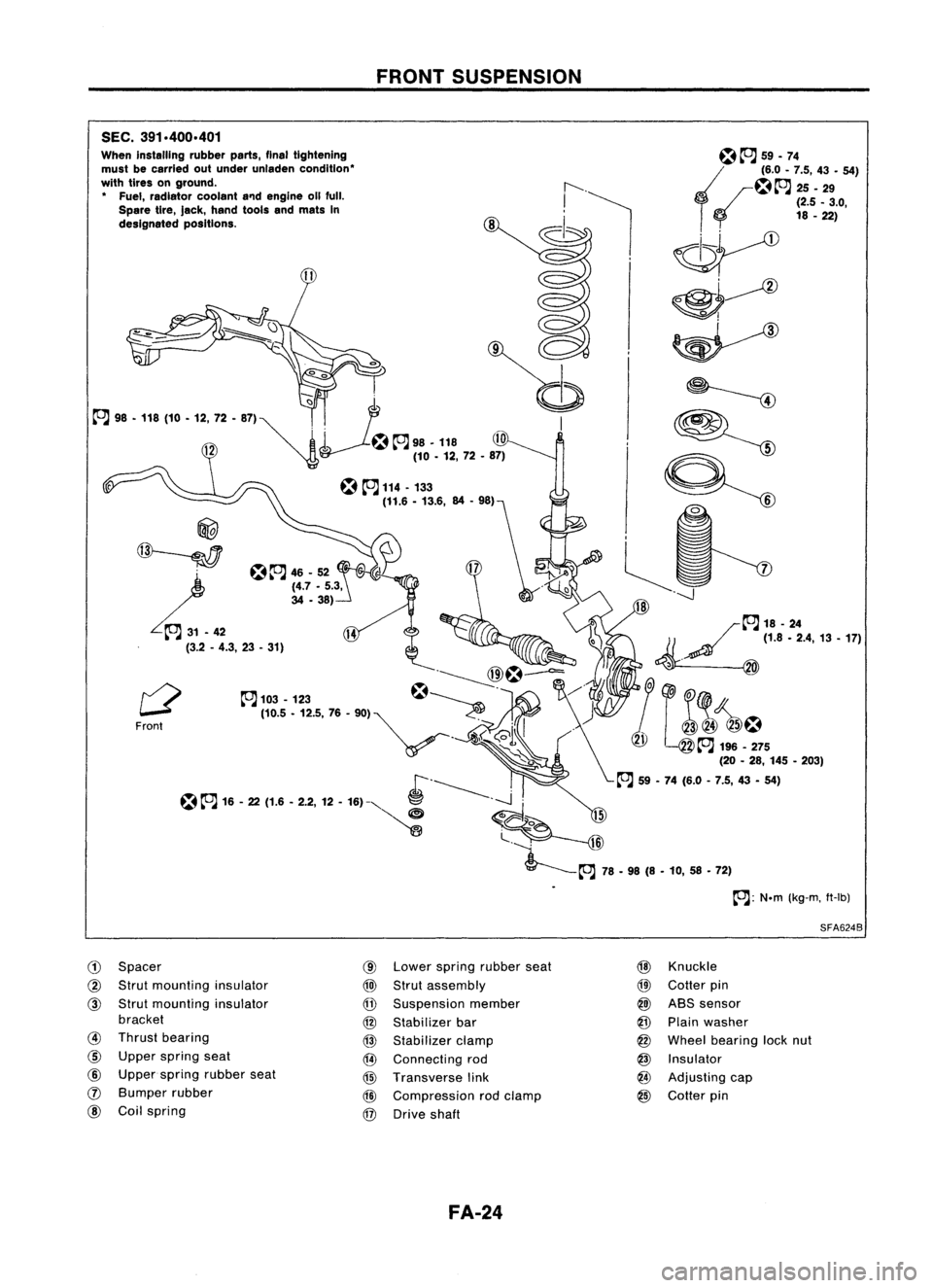
SEC.391.400.401
When installing rubberparts,finaltightening
must becarried outunder unladen condition'
with tires onground.
• Fuel, radiator coolanta'1dengine 011full.
Spare tire,Jack, hand toolsandmats In
designated positions.
@
~
L.~
(3.2-4.3, 23•31)
Front
CD
Spacer
@
Strut mounting insulator
@
Strut mounting insulator
bracket
@
Thrust bearing
@
Upper spring seat
@
Upper spring rubber seat
(J)
Bumper rubber
@
Coilspring
FRONT
SUSPENSION
@
Lower spring rubber seat
@)
Strut assembly
@
Suspension member
@
Stabilizer bar
@
Stabilizer clamp
@
Connecting rod
@
Transverse link
@
Compression rodclamp
@
Drive shaft
FA-24
~~
59.74
~~~.~ ::'.4:9- 54)
o
(2.5_3.0,
18 -22)
~
~~
~ ~
9=:
~~
-----J
/~18-24
1/ ~
(1.8.2.4,13.17)
~. @
&1
(@
~ J~!~5
(20-28, 145 •203)
~ 59•74 (6.0 -7.5, 43•54)
SFA624B
@
Knuckle
@
Cotter pin
@)
ABS sensor
@
Plain washer
@
Wheel bearing locknut
@
Insulator
@
Adjusting cap
@
Cotter pin