bulb NISSAN ALMERA N15 1995 User Guide
[x] Cancel search | Manufacturer: NISSAN, Model Year: 1995, Model line: ALMERA N15, Model: NISSAN ALMERA N15 1995Pages: 1701, PDF Size: 82.27 MB
Page 486 of 1701

EXTERIORLAMP
Bulb Specifications
Front turnsignal lamp
Clearance lamp
Front foglamp
Side turnsignal lamp
Rear combination lamp
Turn signal
StoplTail
Tail Back-up
Rear fog
License platelamp
High-mounted stoplamp
Bulb type(Sedan)
Bulb type(Hatchback)
LED type
EL-114
Wattage
(W)
21
5
55
5
21
21/5
5
21
21 5
5 (x6)
21
4.6
Page 498 of 1701

INTERIORLAMP
Bulb Specifications
Interior lamp
Spot lamp
Turn room lamp
Luggage roomlamp
EL-126
Wattage
(W)
10
10
3,4
3,4
Page 523 of 1701

Ohmmeter- + WARNING
LAMPSANDBUZZER
Oil Pressure SwitchCheck
Oil pressure
Continuity
kPa (bar, kg/cm
2,
psi)
More than10-20
NO
Engine
start
(0.10-0.20, 0.1-0.2, 1.4-2.8)
Less than10-20
YES
Engine
stop
(0.10-0.20, 0.1-0.2, 1.4-2.8)
SEL748K
Test lamp 3.4WON
\ ,I
"
/
Ballery
Test lamp 3.4W OFF
~0
CD
Ballery
Gasoline MEL623D
SEL901F
Check
thecontinuity betweentheterminals ofoil pressure
switch andbody ground.
Fuel Warning LampSensor Check
• Itwill take ashort timeforthe bulb tolight.
Diode Check
• Check continuity usinganohmmeter.
• Diode isfunctioning properlyiftest results areasshown in
the figure atleft.
NOTE:
Specification mayvary depending onthe type oftester. Before
performing thisinspection, besure torefer tothe instruction
manual forthe tester tobe used.
• Diodes forwarning lampsarebuilt intothecombination
meter printed circuit.
Refer to"Combination Meter"(EL-127).
Warning BuzzerUnit
• Seat beltwarning lampiscontrolled bythe warning buzzer
unit.
Refer to"Warning Buzzer"(EL-152).
EL-151
•
Page 763 of 1701

1. The malfunction indicatorlampwilllight upwhe")
ON-BOARDDIAGNOSTIC SYSTEMDESCRIPTION
\ I/
'e/'
-
CHECK-
/
.......
/ I\
Malfunction indicator
lamp SEF051PA
Malfunction
Indicatorlamp(Mil)
1. The malfunction indicatorlampwilllight upwhen theigni-
tion switch isturned ONwithout theengine running. Thisis
a bulb check.
• If
the malfunction indicatorlampdoes notlight up,refer to
EL section ("WARNING LAMPSANDCHIME") orsee
EC-223.
2. When theengine isstarted, themalfunction indicatorlamp
should gooff.
Condition Diagnostic
Diagnostic
Test Mode I TestMode II
Engine
stopped BULBCHECK SELF-DIAGNOSTIC
Ignition
~
RESULTS
switch in
"ON" posi-
tion Engine
*1
~
running
MALFUNCTION
OXYGENSENSOR
ID
WARNING
MONITOR
*1: Heated oxygen sensor(ForEurope andIsrael, andAustralia AITmodels)
Oxygen sensor(Except forEurope andIsrael, andAustralia AITmodels)
EC-44
Page 764 of 1701
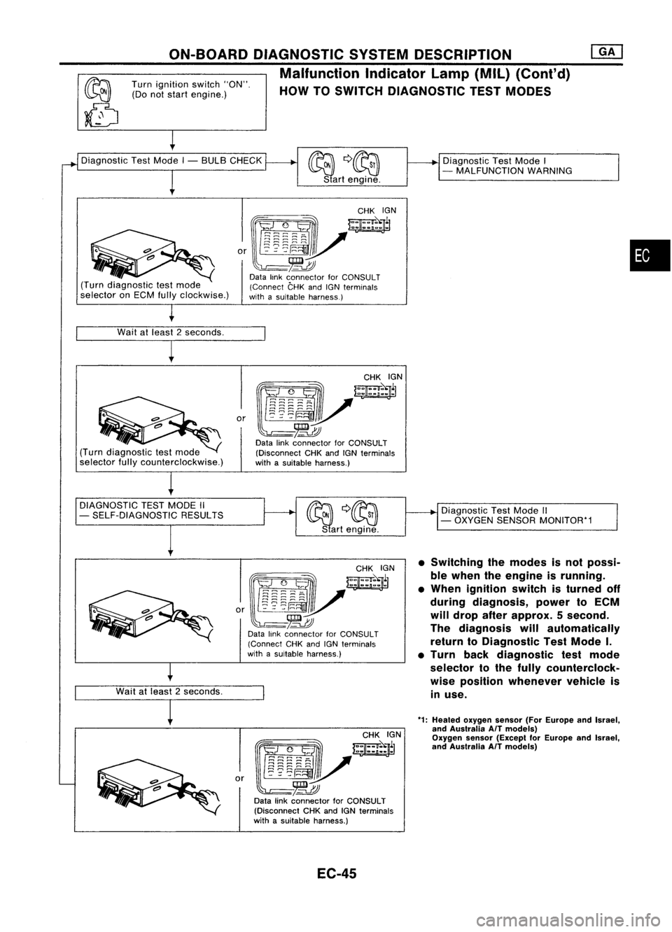
Turnignition switch"ON".
(Do notstart engine.)
ON-BOARD
DIAGNOSTIC SYSTEMDESCRIPTION
Malfunction Indicatorlamp(Mil)(Cont'd)
HOW TOSWITCH DIAGNOSTIC TESTMODES
Diagnostic TestMode I- BULB CHECK
DiagnosticTestMode I
- MALFUNCTION WARNING
(Turn diagnostic testmode
selector onECM fullyclockwise.)
o,~yr;;~N
~-~
Data linkconnector forCONSULT
(Connect CHKandIGNterminals
with asuitable harness.)
•
Wait atleast 2seconds.
(Turn diagnostic testmode
selector fullycounterclockwise.)
O,~/~N
~-~
Data linkconnector forCONSULT
(Disconnect CHKandIGNterminals
with asuitable harness.)
DIAGNOSTIC TESTMODE II ~
Q~
- SELF-DIAGNOSTIC RESULTS ON~
S art engine. Diagnostic
TestMode II
- OXYGEN SENSOR MONITOR*1
Wait atleast 2seconds.
1
*1:
Heated oxygen sensor(ForEurope andIsrael,
and Australia AfTmodels)
Oxygen sensor(Except forEurope andtsrael,
and Australia AfTmodels)
•
Switching themodes isnot possi-
ble when theengine isrunning.
• When ignition switchisturned off
during diagnosis, powertoECM
will drop afterapprox. 5second.
The diagnosis willautomatically
return toDiagnostic TestMode I.
• Turn backdiagnostic testmode
selector tothe fully counterclock-
wise position whenever vehicleis
in use.
~~Ol
W:jr
g2g~E;V
~~~;::
or
-~
Data linkconnector forCONSULT
(Disconnect CHKandIGNterminals
with asuitable harness.)
[gJ~~~~~~
~~r
0'
~!~~:V
-~
Data linkconnector forCONSULT
(Connect CHKandIGNterminals
with asuitable harness.)
EC-45
Page 765 of 1701
ON-BOARDDIAGNOSTIC SYSTEMDESCRIPTION @KJ
Malfunction Indicatorlamp(Mil)(Cont'd)
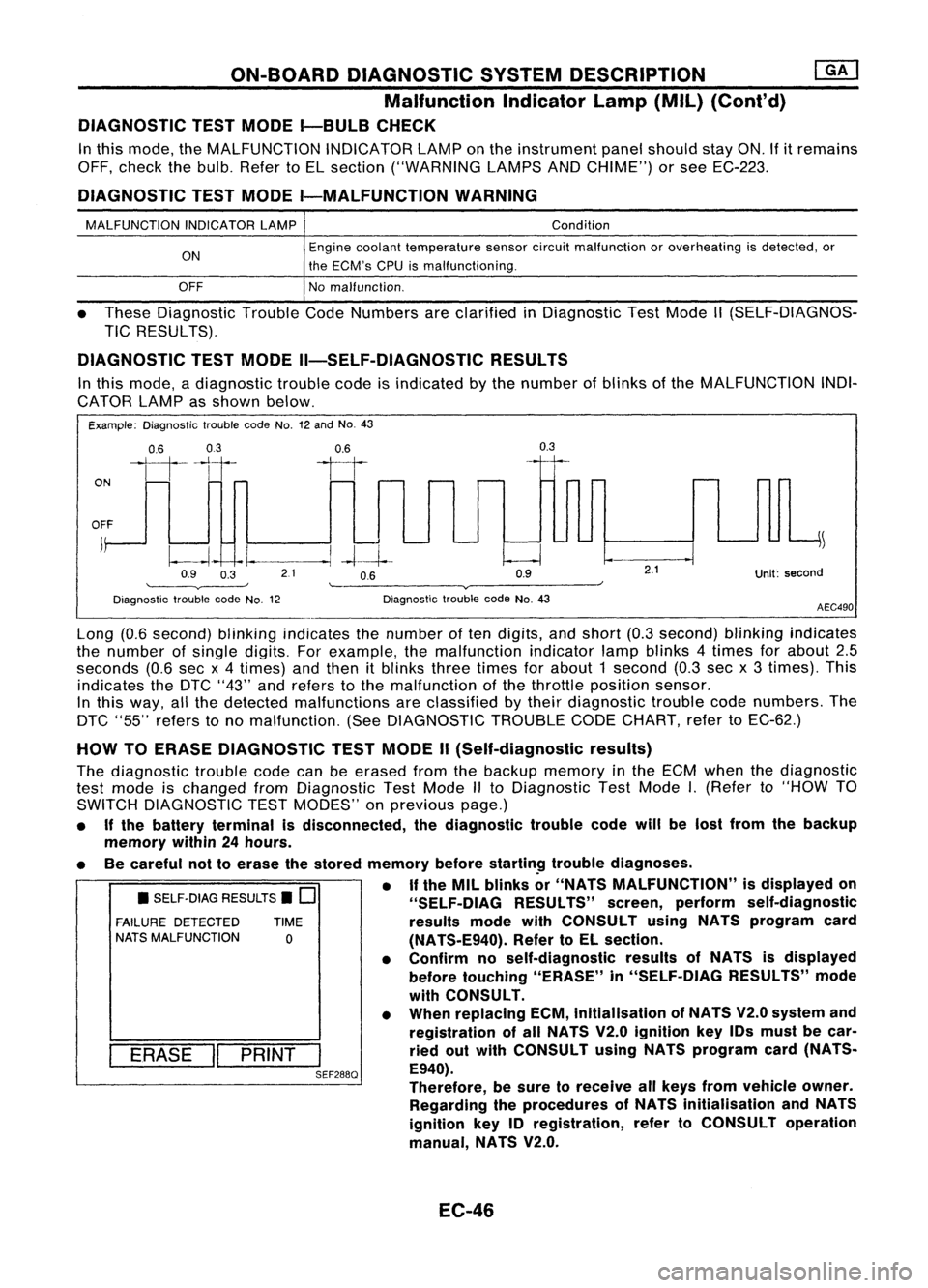
DIAGNOSTIC TESTMODE I-BULB CHECK
In this mode, theMALFUNCTION INDICATORLAMPonthe instrument panelshould stayON.Ifitremains
OFF, check thebulb. Refer toEL section ("WARNING LAMPSANDCHIME") orsee EC-223.
DIAGNOSTIC TESTMODE I-MALFUNCTION WARNING
MALFUNCTION INDICATORLAMP
ON
OFF Condition
Engine coolant temperature sensorcircuitmalfunction oroverheating isdetected, or
the ECM's CPUismalfunctioning.
No malfunction.
• These Diagnostic TroubleCodeNumbers areclarified inDiagnostic TestMode II(SELF-DIAGNOS-
TIC RESULTS).
DIAGNOSTIC TESTMODE II-SELF-DIAGNOSTIC RESULTS
In this mode, adiagnostic troublecodeisindicated bythe number ofblinks ofthe MALFUNCTION INDI-
CATOR LAMPasshown below.
Example: Diagnostic troublecodeNo.12and No.43
ON
0.6
03
111-'1
0.6
II
0.3
OFF
j
~
~~ -I.
--.1
-4--1--
Q9 O~ 21 OB Q9
'--------v----' '--------v------~
Diagnostic troublecodeNo.12 DiagnostictroublecodeNo.43
2.1
Unit:second
AEC490
• SELF-DIAG RESULTS.
0
FAILURE DETECTED TIME
NATS MALFUNCTION
0
I
ERASE
II
PRINT
I
SEF288Q
Long
(0.6second) blinkingindicates thenumber often digits, andshort (0.3second) blinkingindicates
the number ofsingle digits. Forexample, themalfunction indicatorlampblinks 4times forabout 2.5
seconds (0.6secx4 times) andthen itblinks threetimes forabout 1second (0.3secx3 times). This
indicates theDTC "43" andrefers tothe malfunction ofthe throttle position sensor.
In this way, allthe detected malfunctions areclassified bytheir diagnostic troublecodenumbers. The
DTC "55" refers tono malfunction. (SeeDIAGNOSTIC TROUBLECODECHART, refertoEC-62.)
HOW TOERASE DIAGNOSTIC TESTMODE II(Self-diagnostic results)
The diagnostic troublecodecanbeerased fromthebackup memory inthe ECM when thediagnostic
test mode ischanged fromDiagnostic TestMode IIto Diagnostic TestMode
I.
(Refer to"HOW TO
SWITCH DIAGNOSTIC TESTMODES" onprevious page.)
• Ifthe battery terminal isdisconnected, thediagnostic troublecodewillbelost from thebackup
memory within24hours.
• Becareful nottoerase thestored memory before
startin~
troublediagnoses.
• If
the MIL blinks or"NATS MALFUNCTION" isdisplayed on
"SELF-OIAG RESULTS"screen,perform self-diagnostic
results modewithCONSULT usingNATS program card
(NATS-E940). RefertoEL section.
• Confirm noself-diagnostic resultsofNATS isdisplayed
before touching "ERASE" in"SELF-DIAG RESULTS"mode
with CONSULT.
• When replacing ECM,initialisation ofNATS V2.0system and
registration ofall NATS V2.0ignition key10smust becar-
ried outwith CONSULT usingNATS program card(NATS-
E940).
Therefore, besure toreceive allkeys from vehicle owner.
Regarding theprocedures ofNATS initialisation andNATS
ignition key10registration, refertoCONSULT operation
manual, NATS V2.0.
EC-46
Page 969 of 1701

1. The malfunction indicatorlampwilllight upwhen theigni-
tion switch istur")
ON-BOARDDIAGNOSTIC SYSTEMDESCRIPTION
\ I/
'~/'
- CHECK-
/
.......
/ I\
SEF051P
Malfunction
Indicatorlamp(Mil)
1. The malfunction indicatorlampwilllight upwhen theigni-
tion switch isturned ONwithout theengine running. Thisis
a bulb check.
• Ifthe malfunction indicatorlampdoes notlight up,refer to
EL section ("WARNING LAMPSANDCHIME") orsee
EC-370.
2. When theengine isstarted, themalfunction indicatorlamp
should gooff.
Condition Diagnostic
Diagnostic
Test Mode I TestMode II
Engine
stopped BULBCHECK SELF-DIAGNOSTIC
Ignition
0
RESULTS
switch in
"ON" posi-
tion Engine
HEATEDOXYGEN
~ running
MALFUNCTION
SENSORMONI-
ID
WARNING
TOR
EC-250
Page 970 of 1701
ON-BOARDDIAGNOSTIC SYSTEMDESCRIPTION
Malfunction IndicatorLamp(MIL)(Cont'd)
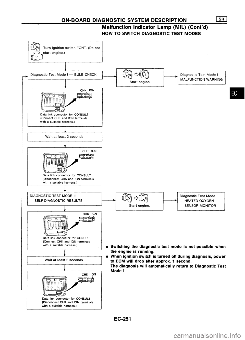
HOW TOSWITCH DIAGNOSTIC TESTMODES
~ Turnignition switch"ON".(Donot
~ startengine.)
~
•SWitching thediagnostic testmode isnot possible when
the engine isrunning.
• When ignition switchisturned offduring diagnosis, power
to ECM willdrop afterapprox. 1second.
The diagnosis willautomatically returntoDiagnostic Test
Mode
I.
Diagnostic
TestMode I- BULB CHECK
1
~yW~r
~-~
Data linkconnector forCONSULT
(Connect CHKandIGNterminals
with asuitable harness.)
Wait atleast 2seconds.
CHKIGN
~J/~l
~-~
Data linkconnector forCONSULT
(Disconnect CHKandIGNterminals
with asuitable harness.)
DIAGNOSTIC TESTMODE II
- SELF-DIAGNOSTIC RESULTS
~
f!i~:~~-~
w;ir
l~mv
-~
Data linkconnector forCONSULT
(Connect CHKandIGN terminals
with asuitable harness.)
Wait atleast 2seconds.
~
~/~~N
~-~
Data linkconnector forCONSULT
(Disconnect CHKandIGNterminals
with asuitable harness.)
I
Startengine.
Start engine. Diagnostic
TestMode I-
MALFUNCTION WARNING
Diagnostic TestMode II
- HEATED OXYGEN
SENSOR MONITOR
•
EC-251
Page 971 of 1701
ON-BOARDDIAGNOSTIC SYSTEMDESCRIPTION ~
Malfunction IndicatorLamp(MIL)(Cont'd)
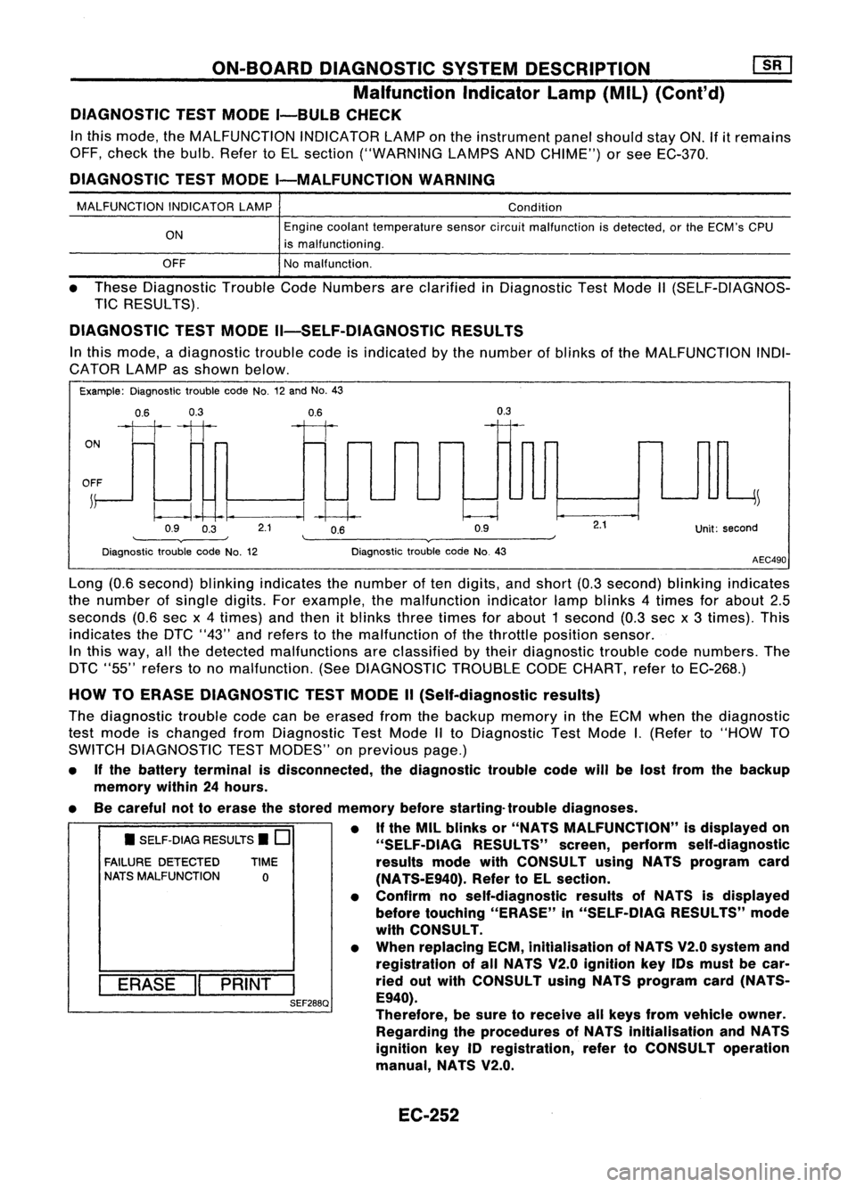
DIAGNOSTIC TESTMODE I-BULB CHECK
In this mode, theMALFUNCTION INDICATORLAMPonthe instrument panelshould stayON.If
it
remains
OFF, check thebulb. Refer toEL section ("WARNING LAMPSANDCHIME") orsee EC-370.
DIAGNOSTIC TESTMODE I-MALFUNCTION WARNING
MALFUNCTION INDICATORLAMP
ON
OFF Condition
Engine coolant temperature sensorcircuitmalfunction isdetected, orthe ECM's CPU
is malfunctioning.
No malfunction.
• These Diagnostic TroubleCodeNumbers areclarified inDiagnostic TestMode II(SELF-DIAGNOS-
TIC RESULTS).
DIAGNOSTIC TESTMODE II-SELF-DIAGNOSTIC RESULTS
In this mode, adiagnostic troublecodeisindicated bythe number ofblinks ofthe MALFUNCTION INDI-
CATOR LAMPasshown below.
Example: Diagnostic troublecodeNo.12and No.43
0.6 0.3
ON
1111
OFF ~
0.9 0.3
0.6
--I~
2.1 0.6
0.9
0.3
Unit:second
Diagnostic troublecodeNo.12 Diagnostic
troublecodeNo.43
AEC490
• SELF-DIAG RESULTS.
0
FAILURE DETECTED TIME
NATS MALFUNCTION
0
I
ERASE
II
PRINT
I
SEF288Q
Long
(0.6second) blinkingindicates thenumber often digits, andshort (0.3second) blinkingindicates
the number ofsingle digits.Forexample, themalfunction indicatorlampblinks 4times forabout 2.5
seconds (0.6secx4times) andthen itblinks threetimes forabout 1second (0.3sec x3 times). This
indicates theDTC "43" andrefers tothe malfunction ofthe throttle position sensor.
In this way, allthe detected malfunctions areclassified bytheir diagnostic troublecodenumbers. The
DTC "55" refers tono malfunction. (SeeDIAGNOSTIC TROUBLECODECHART, refertoEC-268.)
HOW TOERASE DIAGNOSTIC TESTMODE II(Self-diagnostic results)
The diagnostic troublecodecanbeerased fromthebackup memory inthe ECM when thediagnostic
test mode ischanged fromDiagnostic TestMode IIto Diagnostic TestMode
I.
(Refer to"HOW TO
SWITCH DIAGNOSTIC TESTMODES" onprevious page.)
• Ifthe battery terminal isdisconnected, thediagnostic troublecodewillbelost from thebackup
memory within24hours.
• Becareful nottoerase thestored memory beforestarting- troublediagnoses.
• Ifthe MIL blinks or"NATS MALFUNCTION" isdisplayed on
"SELF-OIAG RESULTS"screen,perform self-diagnostic
results modewithCONSULT usingNATS program card
(NA TS-E940). RefertoEL section.
• Confirm noself-diagnostic resultsofNATS isdisplayed
before touching "ERASE" in"SELF-DiAG RESULTS"mode
with CONSULT.
• When replacing ECM,inltialisation ofNATS V2.0system and
registration ofall NATS V2.0 Ignition keyIDsmust becar-
ried outwith CONSULT usingNATS program card(NATS-
E940).
Therefore, besure toreceive allkeys from vehicle owner.
Regarding theprocedures ofNATS initialisation andNATS
ignition key
10
registration, refertoCONSULT operation
manual, NATS V2.0.
EC-252
Page 1116 of 1701
TROUBLEDIAGNOSES ~
Quick-glow System(Cont'd)
• If
NG.
check component partsandtheir related harness
according tothe following chart.
Parts which should bechecked
Terminal Fuse Glowin-
No. Battery IFusible Glow
Key-in Ignition
dicatorHarness
link relay
switch switch
bulb
@
XX
X
@
X
X X X
@
XX
X X
@,@
XX XX
@
XX X
X X
@
X
X XX
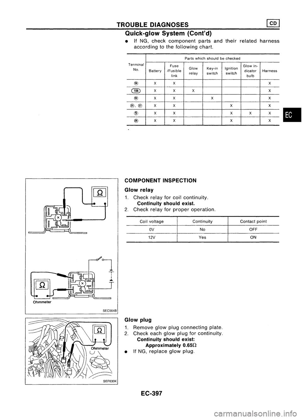
COMPONENT INSPECTION
Glow relay
1. Check relayforcoil continuity.
Continuity shouldexist.
2. Check relayforproper operation.
Coil voltage Continuity
Contactpoint
OV
NoOFF
12V
Yes ON
•
Ohmmeter SEC5648
SEF630K Glow
plug
1. Remove glowplugconnecting plate.
2. Check eachglow plugforcontinuity.
Continuity shouldexist:
Approximately 0.650
• IfNG, replace glowplug.
EC-397