wheel torque NISSAN ALMERA N15 1995 User Guide
[x] Cancel search | Manufacturer: NISSAN, Model Year: 1995, Model line: ALMERA N15, Model: NISSAN ALMERA N15 1995Pages: 1701, PDF Size: 82.27 MB
Page 1087 of 1701

TROUBLEDIAGNOSIS FORNON-DETECTABLE ITEMS~
Torque Converter ClutchSolenoid Valve(Cont'd)
SYSTEM DESCRIPTION
Throttle position sensor Throttle
valveopening angle
Engine coolant temperature sensorEnginecoolant temperature ECM
(ECCS
control
module) Torque
converter
clutch solenoid
valve
Vehicle speedsensor Vehicle
speed
The
AfT
lock-up iscontrolled bythe ECM through
the torque converter clutchsolenoid valve.When
the ECM detects anyofthe following conditions,
the ECM switches thetorque converter clutch
solenoid valveOFFtoaccomplish lock-upopera-
tion. While thevehicle isinconditions otherthan
below, thetorque converter clutchsolenoid valve
is always settoON, relea'sing thelock-up oper-
ation. •
Throttle position isopen .
• Engine coolant temperature is70°C (158°F) or
more .
• Vehicle speedis58 kmfh (36MPH) ormore.
~i3~
II
ECM
E[CONNECTORII
DIAGNOSTIC
PROCEDURE
INSPECTION START
115
OK
INSPECTION END
CHECK
COMPONENT
(Torque converter clutch
solenoid valve).
Refer to"Electrical Com-
ponents Inspection" in
AT section.
If
NG, replace torque
converter clutchsolenoid
valve.
Check thefollowing.
• Harness connectors
@,
• 10A fuse
• Harness foropen or
short between torque
converter clutchsole-
noid valve andfuse
If NG, repair harness or
connectors.
NG
OK
OK
@
CHECK
CONTROL FUNCTION.
1. Jack updrive wheels.
2. Start engine andwarm itup suffi-
ciently.
3. Shift selector leverto"0" position.
4. Check voltage between ECMterminal
GID
andground underthefollowing
conditions.
Voltage: Accelerator pedalIsdepressed
[Vehicle speedisabove
58 km/h (36MPH).]
Battery voltage
Accelerator pedalisfully
released
Approximately OV
CHECK POWER SUPPLY.
1. Stop engine.
2. Disconnect torqueconverter clutch
solenoid valveharness connector.
3. Turn ignition switch"ON".
4. Check voltage between terminal
@
and ground.
Voltage: Batteryvoltage
-
MEC785B
MEC279BA
Ef
CONNECTOR
II
115
II
ECM
~~
ID
cf8~-H
EC-368
Page 1355 of 1701
GENERALINFORMATION •
SECTION
G
I
CONTENTS
PRECAUTIONS 2
Supplemental RestraintSystem(SRS)"AIR
BAG" (DualAirBag System) 2
Supplemental RestraintSystem(SRS)"AIR
BAG" (Single AirBag System) 2
Precautions forNATS V2.0(ForGasoline
Engine Model) 3
General Precautions 3
Precautions forMultiport FuelInjection
System orECCS Engine 5
Precautions forThree WayCatalyst 5
Engine Oils 5
Precautions forFuel 6
HOW TOUSE THIS
MANUAL 7
HOW TOREAD WIRING DIAGRAMS 9
Sample/Wiring Diagram-EXAMPL - 9
Description 11
Wiring Diagram Codes(CellCodes) 17
HOW TOPERFORM EFFICIENT DIAGNOSIS FOR
AN ELECTRICAL INCIDENT 18
Work Flow 18
Incident Simulation Tests 19
Circuit Inspection 23
HOW
TOFOLLOW FLOWCHART INTROUBLE
DIAGNOSES 29
CONSULT CHECKING SYSTEM
32
Function andSystem Application 32
Lithium BatteryReplacement.. 32
Checking Equipment 32
IDENTIFICATION INFORMATION 33
Model Variation 33
Identification Number 36
Di mens ions 39
Wheels andTires 39
LIFTING POINTSANDTOW TRUCK TOWING ..40
Preparation 40
Board-on
Lift
40
Garage JackandSafety Stand 41
2-pole Lift 42
Tow Truck Towing 43
TIGHTENING TORQUEOFSTANDARD BOLTS
44
SAE J1930 TERMINOLOGY LIST 45
SAE J1930 Terminology List.. 45
Page 1536 of 1701
0
0
•
0
0
~ /0
H
H
0
0
(2)
4wheels
5 wheels
SMA785C
Radial
tires
CHASSIS
ANDBODY MAINTENANCE
Tire Rotation
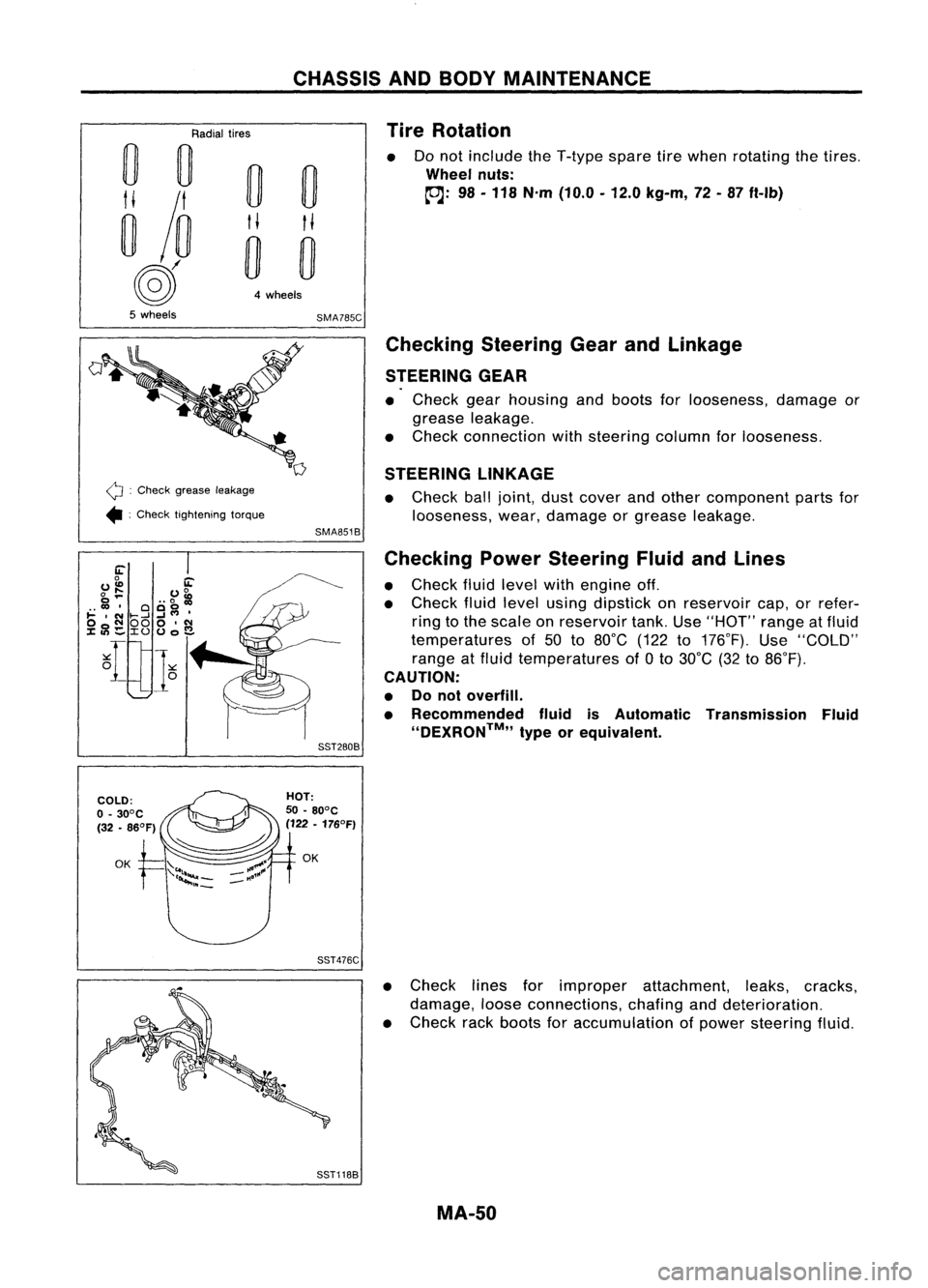
Do not include theT-type sparetirewhen rotating thetires .
Wheel nuts:
~: 98-118 N'm (10.0 -12.0 kg-m, 72-87 ft-Ib)
Q :
Check grease leakage
• :Check tightening torque
Checking
SteeringGearandLinkage
STEERING GEAR
• Check gearhousing andboots forlooseness, damageor
grease leakage.
• Check connection withsteering columnforlooseness.
STEERING LINKAGE
• Check balljoint, dustcover andother component partsfor
looseness, wear,damage orgrease leakage.
SMA851B
Checking PowerSteering FluidandLines
• Check fluidlevel withengine off.
• Check fluidlevel using dipstick onreservoir cap,orrefer-
ring tothe scale onreservoir tank.Use"HOT" rangeatfluid
temperatures of50 to80°C (122to176°F). Use"COLD"
range atfluid temperatures of
a
to 30°C (32to86°F).
CAUTION:
• Donot overfill.
• Recommended fluidisAutomatic Transmission Fluid
''DEXRON™,, typeorequivalent.
SST280B
SST476C
•Check linesforimproper attachment, leaks,cracks,
damage, looseconnections, chafinganddeterioration.
• Check rackboots foraccumulation ofpower steering fluid.
MA-50
Page 1610 of 1701
PRECAUTIONSANDPREPARATION
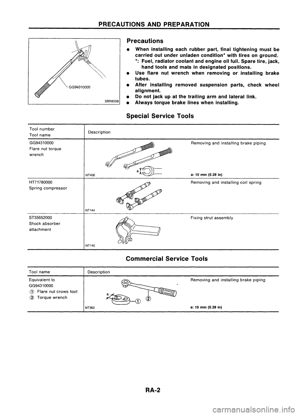
SBR820B Precautions
• When installing eachrubber part,finaltightening mustbe
carried outunder unladen condition* withtires onground.
*:
Fuel, radiator coolantandengine oilfull. Spare tire,jack,
hand tools andmats indesignated positions.
• Use flare nutwrench whenremoving orinstalling brake
tubes.
• After installing removedsuspension parts,check wheel
alignment.
• Donot jack upatthe trailing armandlateral link.
• Always torquebrakelineswhen installing.
Special Service Tools
Tool number
Tool name Description
GG9431 0000
Flare nuttorque
wrench
HT71780000
Spring compressor
ST35652000
Shock absorber
attachment
NT406
NT144
NT145
Removing
andinstalling brakepiping
a:
10
mm
(0.39
in)
Removing andinstalling coilspring
Fixing strutassembly
Tool name
Description
Commercial
ServiceTools
Equivalent to
GG9431 0000
G)
Flare nutcrows
foot
@
Torque wrench Removing
andinstalling brakepiping
NT360
a:
10
mm
(0.39
in)
RA-2
Page 1612 of 1701

SMA525A
SMA113
---I
SRA690A ON-VEHICLE
SERVICE
Rear AxleandRear Suspension Parts
Check axleandsuspension partsforexcessive play,wear or
damage.
• Shake eachrearwheel tocheck forexcessive play.
• Retighten allnuts andbolts tothe specified torque.
Tightening torque:
Refer toREAR SUSPENSION (RA-8).
• Check shockabsorber for
oil
leakage orother damage.
Rear Wheel Bearing
• Check axialendplay.
Axial endplay:
0.05 mm(0.0020 in)orless
• Check thatwheel hubbearings operatesmoothly.
• Check tightening torqueofwheel bearing locknut.
(OJ:
186 •255 N.m (19-26 kg-m, 137•188 ft-Ib)
• Replace wheelbearing assembly ifthere isaxial endplay
or wheel bearing doesnotturn smoothly. RefertoREAR
AXLE -Wheel Hub(RA-6).
RA-4
Page 1614 of 1701

Drum
brake
r2'\
Front ~22-29 (2.2 •3.0, 16-22)
Disc
brake
25 -33(2.5 -3.4, 18-25)
~ :N.m (kg-m. ft-Ib)
G)
Spi")
REARAXLE
Wheel Hub
SEC. 430
SRA710A
6
~
186 •255
(19 •26, 137 -188)
Drum
brake
r2'\
Front ~22-29 (2.2 •3.0, 16-22)
Disc
brake
25 -33(2.5 -3.4, 18-25)
~ :N.m (kg-m. ft-Ib)
G)
Spindle
@
Baffle plate
@
Back plate
@
Wheel hubbearing
@
Washer
@
Wheel bearing locknut
(J)
Cotter pin
@
Hubcap
@
ABS sensor
REMOVAL
CAUTION:
• Before removing therear wheel hubassembly, disconnect
the ABS wheel sensor fromtheassembly. Thenmove it
away fromthehub assembly. Failuretodo somay result in
damage tothe sensor wiresandthesensor becoming inop-
erative.
• Wheel hubbearing doesnotrequire maintenance. Ifany of
the following symptoms arenoted, replace wheelhubbear-
ing assembly.
• Growling noiseisemitted fromwheel hubbearing during
operation.
• Wheel hubbearing dragsorturns roughly. Thisoccurs
when turning hubbyhand afterbearing locknutistightened
to specified torque.
RA-6
Page 1617 of 1701
SRA696A
SRA697A
S
Control rod
Lateral link
~H";""I"
ITorsion
beam
SRA698AREAR
SUSPENSION
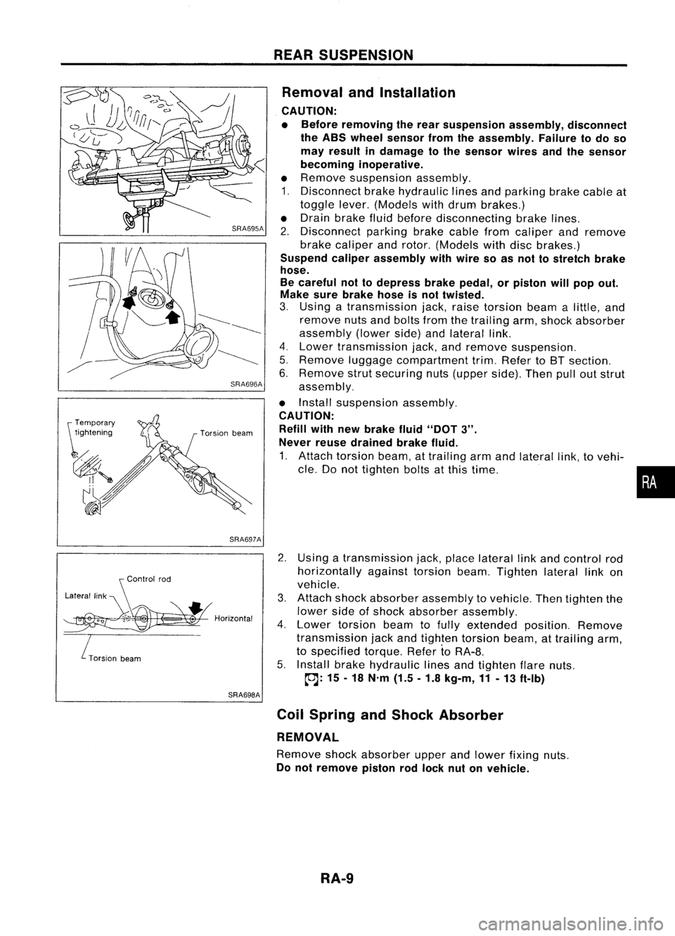
Removal andInstallation
CAUTION:
• Before removing therear suspension assembly,disconnect
the ABS wheel sensor fromtheassembly. Failuretodo so
may result indamage tothe sensor wiresandthesensor
becoming inoperative.
• Remove suspension assembly.
1. Disconnect brakehydraulic linesandparking brakecableat
toggle lever.(Models withdrum brakes.)
• Drain brake fluidbefore disconnecting brakelines.
2. Disconnect parkingbrakecablefromcaliper andremove
brake caliper androtor. (Models withdiscbrakes.)
Suspend caliperassembly withwire soasnot tostretch brake
hose.
Be careful nottodepress brakepedal, orpiston willpop out.
Make surebrake hoseisnot twisted.
3. Using atransmission jack,raise torsion beamalittle, and
remove nutsandbolts fromthetrailing arm,shock absorber
assembly (lowerside)andlateral link.
4. Lower transmission jack,andremove suspension.
5. Remove luggagecompartment trim.Refer toBT section.
6. Remove strutsecuring nuts(upper side).Thenpulloutstrut
assembly.
• Install suspension assembly.
CAUTION: Refill withnewbrake fluid"DOT
3".
Never reusedrained brakefluid.
1. Attach torsion beam,attrailing armandlateral link,tovehi-
cle. Donot tighten boltsatthis time.
2. Using atransmission jack,place lateral linkand control rod
horizontally againsttorsionbeam.Tighten laterallinkon
vehicle.
3. Attach shockabsorber assembly tovehicle. Thentighten the
lower sideofshock absorber assembly.
4. Lower torsion beamtofully extended position.Remove
transmission jackandtighten torsion beam,attrailing arm,
to specified torque.RefertoRA-8.
5. Install brakehydraulic linesandtighten flarenuts.
~: 15-18 N'm (1.5.1.8 kg-m,11-13 ft-Ib)
Coil Spring andShock Absorber
REMOVAL
Remove shockabsorber upperandlower fixing nuts.
Do not remove pistonrodlock nutonvehicle.
RA-9
•
Page 1620 of 1701
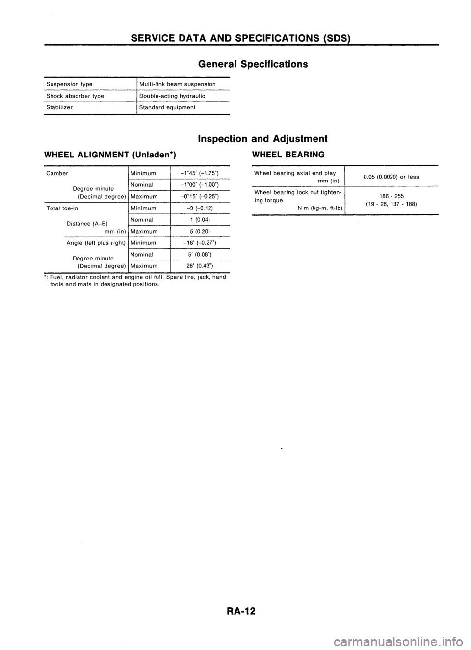
SERVICEDATAANDSPECIFICATIONS (50S)
General Specifications
Suspension type
Shock absorber type
Stabilizer Multi-link
beamsuspension
Double-acting hydraulic
Standard equipment
WHEEL ALIGNMENT (Unladen*) Inspection
andAdjustment
WHEEL BEARING
Camber Minimum-1'45'
(-1.75')
Degree minute Nominal
-1'00'
(-1.00')
(Decimal degree) Maximum -0'15'
(-0.25')
Total toe-in Minimum-3
(-0.12)
Distance (A-B) Nominal
1
(0.04)
mm (in) Maximum 5(0.20)
Angle (leftpius right) Minimum -16'(-0.27')
Degree minute Nominal
5'
(0.08')
(Decimal degree)Maximum 26'
(0.43') Wheel
bearing axialendplay
mm (in)
Wheel bearing locknuttighten-
ing torque
N'm(kg-m. ft-lb) 0.05
(0.0020) orless
186 -255
(19 -26, 137 -188)
': Fuel, radiator coolantandengine oilfull. Spare tire.jack, hand
tools andmats indesignated positions.
RA-12
Page 1669 of 1701

Toolnumber
Tool name PRECAUTIONS
ANDPREPARATION
Special Service Tools
Description
KV481 00700
Torque adapter
KV481 02500
Pressure gaugeadapter NT169
NT542 PF3/B"~
@
@
PF3/B"~ ~x1.5 pitch
M16 x1.5 pitch Measuring
pinionrotating torque
Measuring oilpressure
ST27180001
Steering wheelpuller
NT544(1.14
in)
@Q'O
,'25 0;'0'
@ @
MB
x1.25 pitch Removing
andinstalling steeringwheel
HT72520000
Ball joint remover
ST27091000 Pressure gauge
KV481 04400
Rack sealringreformer
ST3127S000
G)
GG91030000
Torque wrench
@ HT62940000
Socket adapter
@
HT62900000
Socket adapter NT546
NT547
NT550
NT541 To
control valve
Shut-off valve
~ 1/4"~rque wrench
~ withrange of
1/4"
to
3/B" 2.9
N.m
~ ""(30kg-em,
'V
'td"
3/B
to
1/2
26
in-Ib)
ST-3 Removing
balljoint
a:
33
mm
(1.30
in)
b: 50
mm
(1.97
in)
r:
R11.5
mm
(0.453
in)
Measuring oilpressure
Reforming teflonring
a: 50 mm (1.97 in)dia.
b: 36 mm (1.42 in)dia.
c:
100
mm
(3.94
in)
Measuring turningtorque
•
Page 1680 of 1701
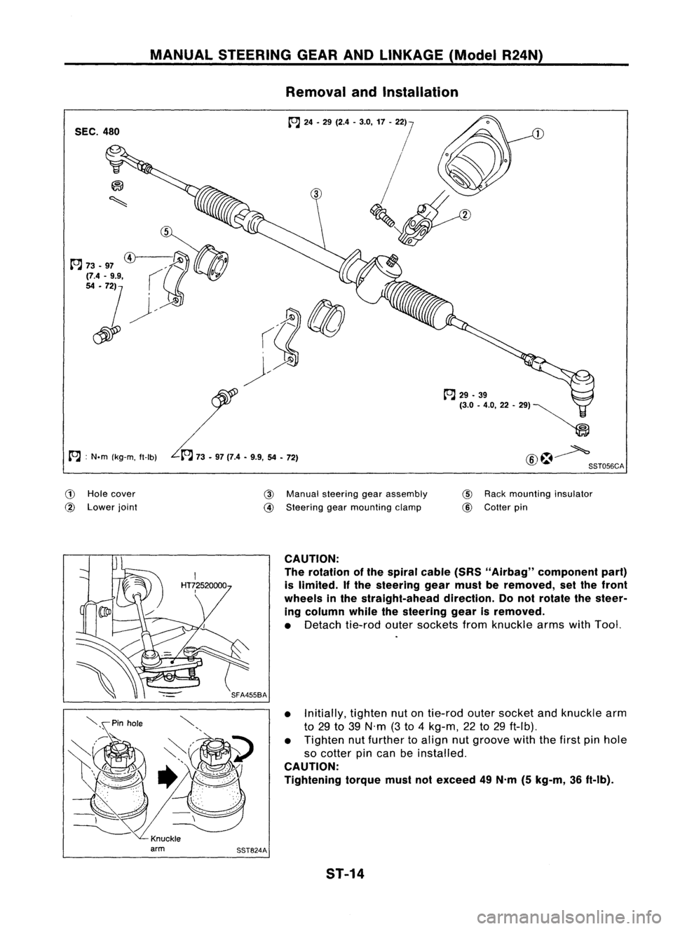
MANUALSTEERING GEARANDLINKAGE (ModelR24N)
Removal andInstallation
SEC. 480
A :
N.m (kg-m, tt-Ib)
(!)
Hole cover
@
Lower joint
@
Manual steering gearassembly
@
Steering gearmounting clamp
tt'J
29•39
(3.0 -4.0,22 -", ~
~
@~ SST056CA
@
Rack mounting insulator
@
Cotter pin
CAUTION:
The rotation ofthe spiral cable(SRS"Airbag" component part)
is limited.
If
the steering gearmust beremoved, setthe front
wheels inthe straight-ahead direction.Donot rotate thesteer-
ing column whilethesteering gearisremoved.
• Detach tie-rodoutersockets fromknuckle armswithTool.
• Initially, tightennutontie-rod outersocket andknuckle arm
to 29 to39 N'm (3to 4kg-m, 22to29 ft-Ib).
• Tighten nutfurther toalign nutgroove withthefirst pinhole
so cotter pincan beinstalled.
CAUTION:
Tightening torquemustnotexceed 49N.m (5kg-m, 36ft-Ib).
ST-14