transmission NISSAN ALMERA N15 1995 Service Manual
[x] Cancel search | Manufacturer: NISSAN, Model Year: 1995, Model line: ALMERA N15, Model: NISSAN ALMERA N15 1995Pages: 1701, PDF Size: 82.27 MB
Page 15 of 1701

DESCRIPTION
Shift Mechanism (Cont'd)
OPERATION OFCLUTCH ANDBRAKE
Bandservo
ForwardLow
Low
&
Shift posi- Reverse
HighForward
Overrun
Lock-upRemarks
tion clutch clutchclutchclutch 2nd
3rd4thone-way
one-way reverse
apply release
applyclutch
clutch brake
P PARK
POSITION
0 0REVERSE
POSI-
R TION
N NEUTRAL
POSI-
TION
1st 0'10
••
D 2nd
0'10
0
•
Automatic
shift
'4 00'10
'2@
@
•
1<-->2<-->3<-->4
3rd
4th 0@ '3@
@0
0
1st 00
••
Automatic
shift
2 1<-->2
2nd 00 0
•
1st 00
•
•
0
Locks
(heldsta-
1 tionary)
in1st
2nd 00 0
•
speed
1
<--
2
'1 Operates whenoverdrive switchissel to"OFF".
'2 Oilpressure isapplied toboth 2nd"apply" sideand3rd"release" sideofband servo piston. However, brakebanddoes notcontract
because oilpressure areaonthe "release" sideisgreater thanthatonthe "apply" side.
'3 Oilpressure isapplied to4th "apply" sideincondition '2above, andbrake bandcontracts.
'4 AIT
will notshift to4th when overdrive switchisset to"OFF" position.
o
Operates.
• Operates. During"progressive" acceleration.
@ Operates butdoes notaffect power transmission.
Control System
CONTROL SYSTEM
Engine
AIT
•
Lock-up cancel
solenoid'1
Overdrive
control switch
1:1
Governor valve
I
11
1
I
1
1
OD cancel solenoid :
; I
L
J
AT-15
'1:
Equipped onmodel
34X69, 34X70and34X80
: Electrical signal
.... :Hydraulic pressure
SAT985HA
Page 17 of 1701

Fluidleakage TROUBLE
DIAGNOSES
Preliminary Check(PriortoRoad Testing)
AIT FLUID CHECK
Fluid leakage check
1. Clean areasuspected ofleaking, -for example, mating
surface ofconverter housingandtransmission case.
2. Start engine, applyfootbrake, placeselector leverin"0"
position andwait afew minutes.
3. Stop engine.
4. Check forfresh leakage.
SAT288G
Fluidcondition check
Fluid levelcheck -Refer toMA section (CHASSIS AND
BODY MAINTENANCE).
Fluid
color
Oark orblack withburned odor
Milky pink
Varnished fluid,lighttodark brown
and tacky Suspected
problem
Wear offrictional material
Water contamination
- Road water entering through
filler tubeorbreather
Oxidation
- Over orunder filling
- Overheating
•
Road Testing
Perform roadtests using "Symptom" chart.Refertopage
AT-20.
"P"
POSITION
1. Place selector leverin"P" position andstart engine. Stop
engine andrepeat theprocedure inall positions, including
neutral position.
2. Stop vehicle onaslight upgrade andplace selector leverin
"P" position. Releaseparkingbraketomake surevehicle
remains locked.
"R"
POSITION
1. Manually moveselector leverfrom"P"to"R", andnote
shift quality.
2. Drive vehicle inreverse longenough todetect slippage or
other abnormalities.
"N"
POSITION
1. Manually moveselector leverfrom"R"and"0"to"N" and
note shift quality.
2. Release parkingbrakewithselector leverin"N" position.
Lightly depress accelerator pedaltomake surevehicle
does notmove. (When vehicle isnew orsoon afterclutches
have been replaced, vehiclemaymove slightly. Thisisnot
a problem.)
AT-17
Page 31 of 1701
ON-VEHICLESERVICE
SAT494HB
Model
34X68 Control
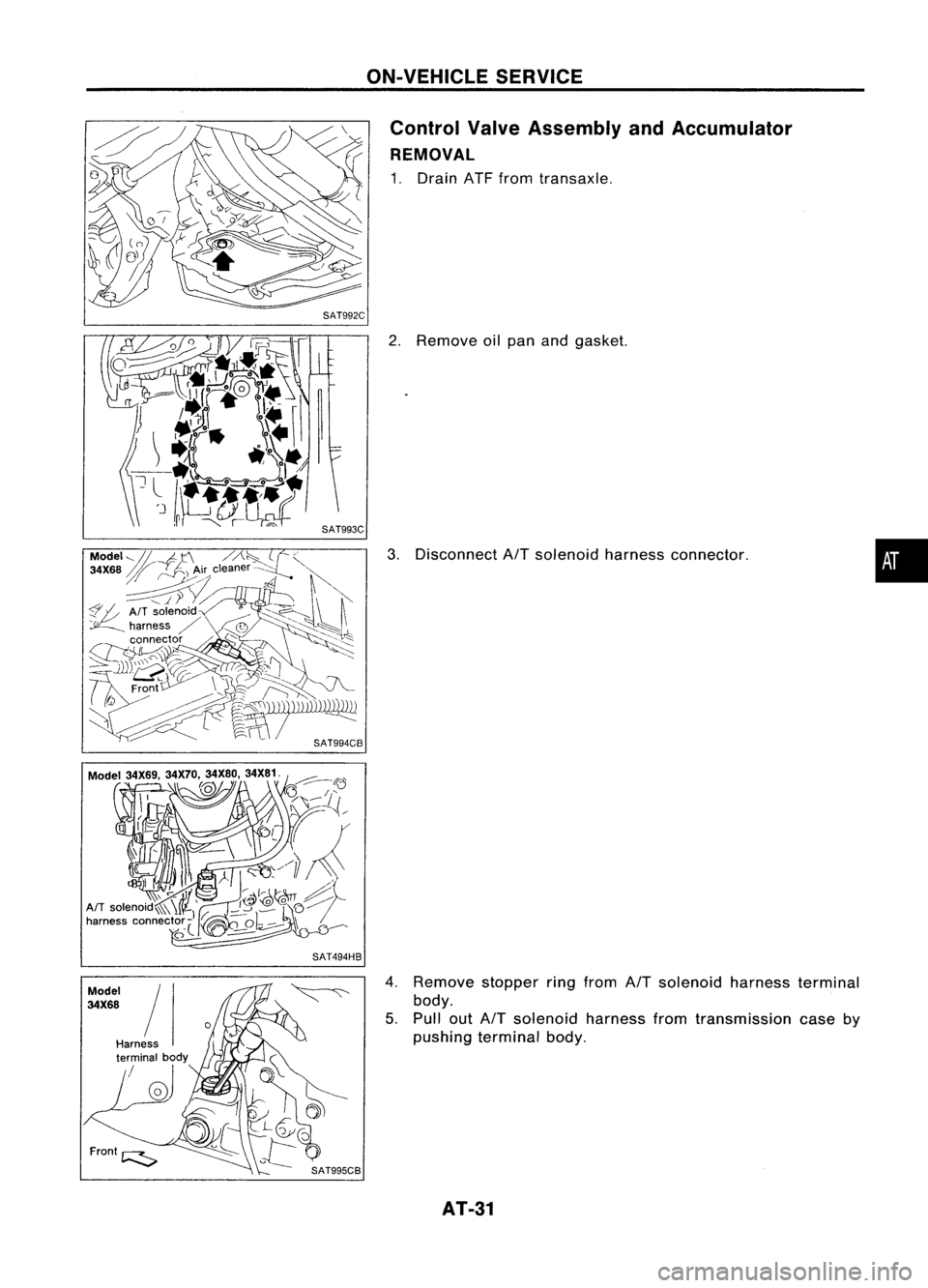
ValveAssembly andAccumulator
REMOVAL
1. Drain ATFfrom transaxle.
2. Remove oilpan andgasket.
3. Disconnect
AfT
solenoid harnessconnector.
4. Remove stopperringfrom
AfT
solenoid harnessterminal
body.
5. Pull out
AfT
solenoid harnessfromtransmission caseby
pushing terminal body.
AT-31
•
Page 38 of 1701

Converterhousingside(RHS)
Transmission caseside(LHS)
SAT259EA ON-VEHICLE
SERVICE
Differential SideOilSeal Replacement (Cont'd)
3. Install oilseals.
• Apply ATFtooil seal surface beforeinstalling.
Converter housing
side •
Install oilseals sothat dimensions
"A"
and
"8"
arewithin
specifications.
Transmission
case side
B
Oil
seal Oil
seal
A
SAT639D
A
5.5 -6.5 (0.217 -0.256)
4. Reinstall anypart removed.
AT-38
Unit:
mm(in)
B
0.5 (0.020)
or
less
Page 52 of 1701
Model
34X68
SAT496HB
SAT0170
DISASSEMBL
Y
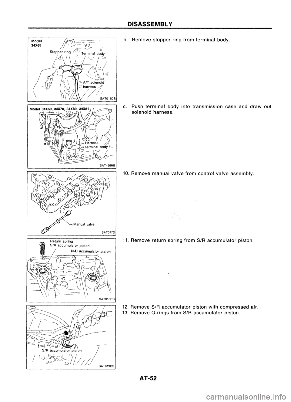
b. Remove stopperringfrom terminal body.
c. Push terminal bodyintotransmission caseanddraw out
solenoid harness.
10. Remove manualvalvefromcontrol valveassembly.
11. Remove returnspring fromSIRaccumulator piston.
12. Remove SIRaccumulator pistonwithcompressed air.
13. Remove O-ringsfromSIRaccumulator piston.
AT-52
Page 54 of 1701

DISASSEMBLV
21. Remove throttlewirefrom throttle lever.
22. Remove throttlewiremounting bolt.
23. Draw outthrottle wirefrom transmission case.
- All models -
24. Remove converter housingaccording tothe following pro-
cedures.
a. Remove converter housingmounting bolts@and
CID.
b. Remove converter housing.
c. Remove O-ringfromdifferential oilport.
AT-54
Page 55 of 1701
KV381054S0SAT030D
SAT132E
SAT840DB
SAT133E DISASSEMBL
V
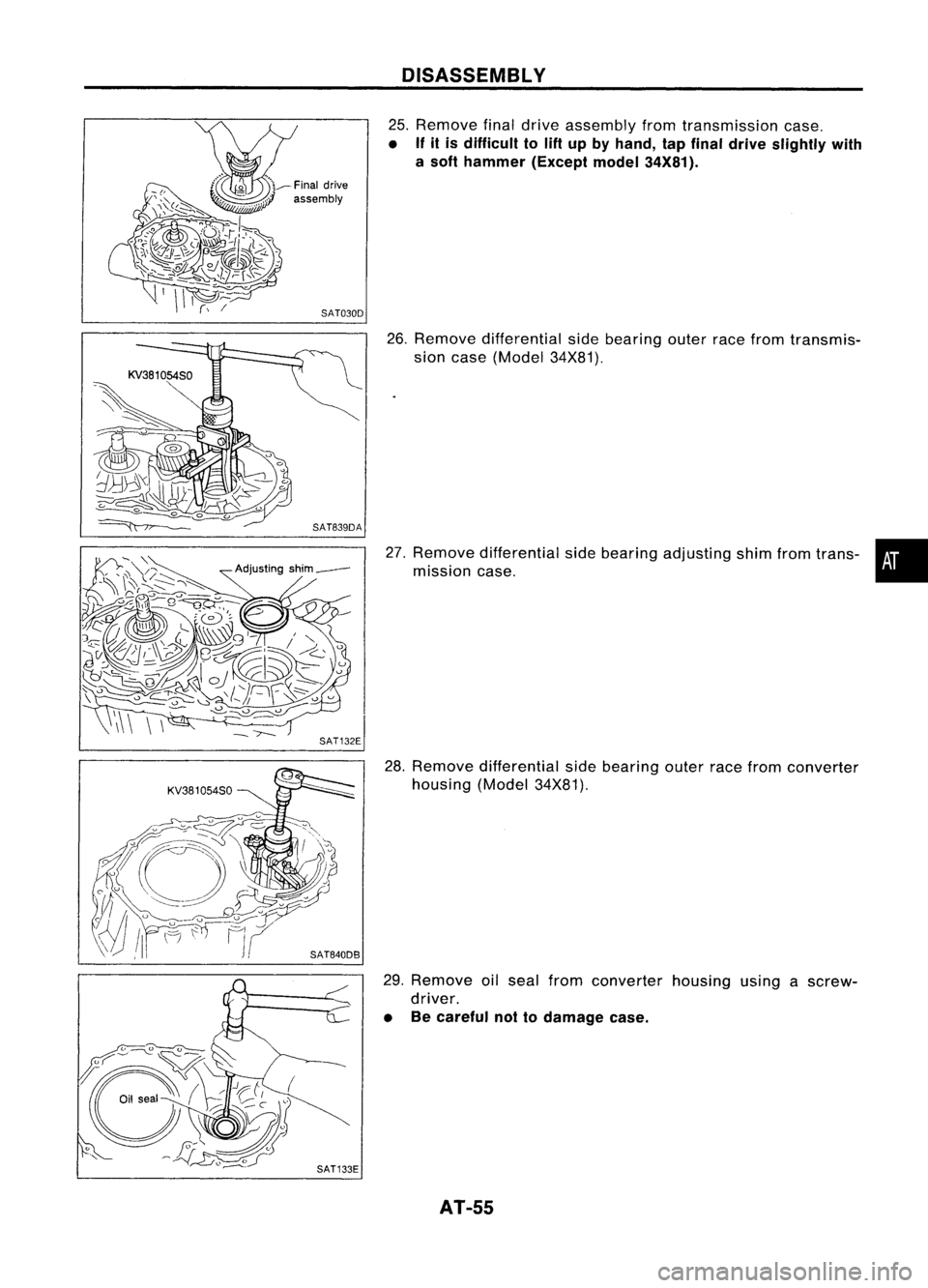
25. Remove finaldrive assembly fromtransmission case.
• If
it is difficult to
lift
up byhand, tapfinal drive slightly with
a soft hammer (Exceptmodel34X81).
26. Remove differential sidebearing outerracefrom transmis-
sion case (Model 34X81).
27. Remove differential sidebearing adjusting shimfromtrans- •
mission case.
28. Remove differential sidebearing outerracefrom converter
housing (Model34X81).
29. Remove oilseal from converter housingusingascrew-
driver.
• Becareful nottodamage case.
AT-55
Page 56 of 1701
SAT134EDISASSEMBL
Y
30. Remove sideoilseal from transmission caseusing ascrew-
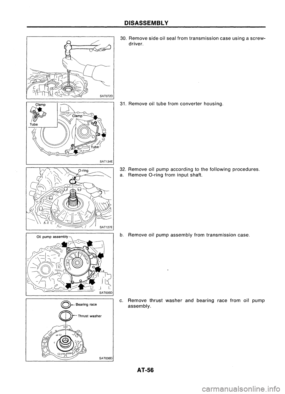
driver.
31. Remove oiltube from converter housing.
32. Remove oilpump according tothe following procedures.
a. Remove O-ringfrominput shaft.
b. Remove oilpump assembly fromtransmission case.
c. Remove thrustwasher andbearing racefrom oilpump
assembly.
AT-56
Page 57 of 1701
l~~
.
_~
Unit:mm(in)
SAT039D DISASSEMBLY
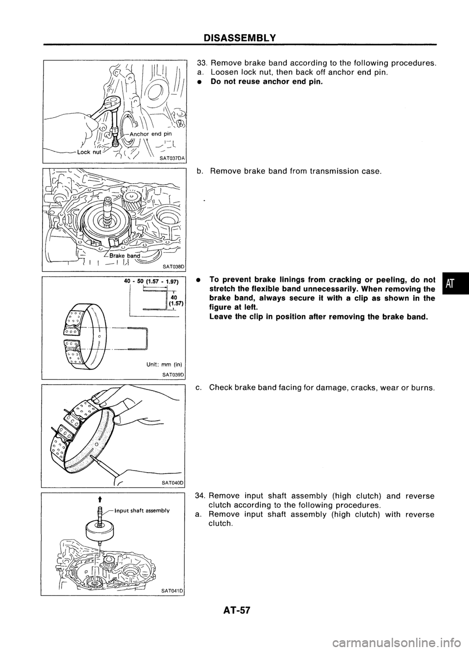
33. Remove brakebandaccording tothe following procedures.
a. Loosen locknut,then back offanchor endpin.
• Donot reuse anchor endpin.
b. Remove brakebandfromtransmission case.
• Toprevent brakelinings fromcracking orpeeling, donot •
stretch theflexible bandunnecessarily. Whenremoving the
i
brake band,always secureitwith aclip asshown inthe
figure atleft.
Leave theclip inposition afterremoving thebrake band.
c. Check brakebandfacing fordamage, cracks,wearorburns.
34. Remove inputshaftassembly (highclutch) andreverse
clutch according tothe following procedures.
a. Remove inputshaft assembly (highclutch) withreverse
clutch.
AT-57
Page 59 of 1701
Frontplanetary carrier
SAT049DDISASSEMBLY
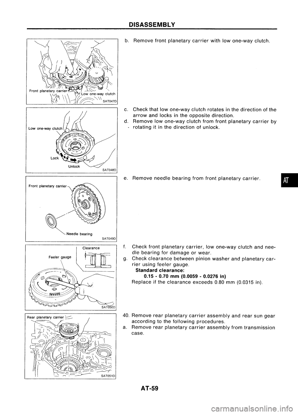
b. Remove frontplanetary carrierwithlowone-way clutch.
c. Check thatlowone-way clutchrotates inthe direction ofthe
arrow andlocks inthe opposite direction.
d. Remove lowone-way clutchfromfront planetary carrierby
rotating itin the direction ofunlock.
e. Remove needlebearing fromfrontplanetary carrier.
•
f. Check frontplanetary carrier,lowone-way clutchandnee-
dle bearing fordamage orwear.
g. Check clearance betweenpinionwasher andplanetary car-
rier using feeler gauge.
Standard clearance:
0.15 -0.70
mm
(0.0059 -0.0276
in)
Replace ifthe clearance exceeds0.80mm(0.0315 in).
40. Remove rearplanetary carrierassembly andrear sungear
according tothe following procedures.
a. Remove rearplanetary carrierassembly fromtransmission
case.
AT-59