Fuse NISSAN ALMERA N15 1995 Owner's Manual
[x] Cancel search | Manufacturer: NISSAN, Model Year: 1995, Model line: ALMERA N15, Model: NISSAN ALMERA N15 1995Pages: 1701, PDF Size: 82.27 MB
Page 389 of 1701

EL-POWER-08
r-----------------------------------------------------------,
•
+
CIGN2)
2 1
5 (ACC2)
FUSE
BLOCK
(..)/B)
(ill)
(105)")
POWERSUPPLY ROUTING
Wiring Diagram -POWER -(ConI' d)
EL-POWER-08
r-----------------------------------------------------------,
•
+
CIGN2)
2 1
5 (ACC2)
FUSE
BLOCK
(..)/B)
(ill)
(105)
7.5A
IT]
@:
ForEurope andIsrael
@:
Except
@
*2'" @W!L @B/P
I
UITIIIIIIIIIill
@
~BR •
LIB +} FICO. A/CCUT •
.. __ LG/R+ A/C
.. ---- LG/R+HEATER, A/C
... ----- LG/R+A/CCUT. A/C
LG/R+} HEATER.A/C
L/W
+
r--------------------------
15A
m
-
o
p
To
EL-POWER
-06
UN.?'
B
I
B
ln
1
JOINT
CONNECTOR-1
@
~
B
I
.
-()~()..,
I
<:
R
:>
I
B B BB
If-II
~~ @
To
EL-POWER ~B/P~
-03 ~
I
~g5EL-POWER ~W/L~()
I
*2
rrm
--------------------------------~
HEL009
EL-17
Page 390 of 1701

EL-POWER-09
To EL-POWER-02
<@-
*1
(
I
l
<D:
LHDmodels
@: RHOmodels
@:
LHDmodels withdaytime lightsystem
qJ): LHDmodels without daytime")
POWERSUPPLY ROUTING
Wiring Diagram -POWER -(Cont'd)
EL-POWER-09
To EL-POWER-02
<@-
*1
(
I
l
LHDmodels
@: RHOmodels
@:
LHDmodels withdaytime lightsystem
qJ): LHDmodels without daytime lightsystem
@:
Except
@
@:
Models withtachometer
*1'"
@R/B qJ)R/Y@R/L
,
,
*3'" (DRIG @R/L
,
*4" .(DRIY @RIL
,
FUSEBLOCK
(JIB)
~
4;106)
@)
UN:
II
r:
II
r:
III
N:
I
UN:
I
UN: I
I
N.a
I
UN.al
I
N..a
I
UN.all
I
~al UN:IliT:
II
~21
*3 RIG RIGRIG RIGRIGRIG RIGRIGRIG RIGRIG
*4
RIL
TN
I.
R/l"TAIL,
FIFOO
*4 •
TAIL
.. ----R/G.
RIG.
RIG.
RIG.
ILL
RIG.
RIG.
RIG.
RIG.
RIG.
BUZZER
RIG.
LOAD
RIG •
AIM. ILL
*3 •
FIFOG
r-------------------------------------------------,
-------------------------------------------------~
HEL010
EL-18
Page 391 of 1701

POWERSUPPLY ROUTING
OK BlownFuse
• Iffuse isblown, besure toeliminate causeofproblem
before installing newfuse.
• Use fuse ofspecified rating.Neverusefuse ofmore than
specified rating.
• Donot partially installfuse;always insertitinto fuse holder
properly.
• Remove fuseforclock ifvehicle isnot used foralong period
of time.
ime (sec.)
100
50
20
10
8
5
CEL083
Fusible Link
A melted fusible linkcan bedetected byvisual inspection.
If
its
condition isquestionable, usecircuit testerortest lamp.
CAUTION:
• Iffusible linkshould melt,itis possible thatcritical circuit
(power supplyorlarge current carrying circuit)isshorted.
In such acase, carefully checkandeliminate causeofprob-
lem.
• Never wrapoutside offusible linkwith vinyl tape.
Important: Neverletfusible linktouch anyother wiring har-
ness orvinyl orrubber parts.
Circuit Breaker
For example, whencurrent is30A, thecircuit isbroken within8
to 20 seconds.
Circuit breakers areused inthe following systems.
• Power window
• Power doorlock
• Electric sunroof
SBF284E
EL-19
•
Page 393 of 1701
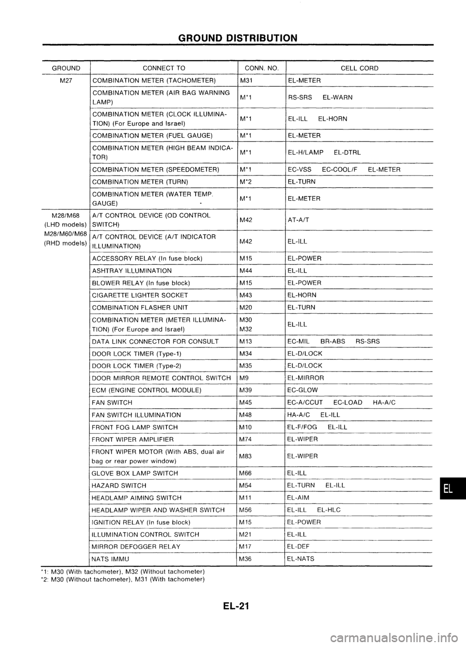
GROUNDDISTRIBUTION
GROUND CONNECT
TO CONN.NO.
CELLCORD
M27 COMBINATION
METER(TACHOMETER) M31EL-METER
COMBINATION METER(AIRBAG WARNING
M'1 RS-SRSEL-WARN
LAMP)
COMBINATION METER(CLOCK ILLUMINA-
M'1 EL-ILL
EL-HORN
TION) (ForEurope andIsrael)
COMBINATION METER(FUELGAUGE) M'1
EL-METER
COMBINATION METER(HIGHBEAM INDICA-
M'1 EL-H/LAMPEL-DTRL
TOR)
COMBINATION METER(SPEEDOMETER) M'1
EC-VSSEC-COOLIF EL-METER
COMBINATION METER(TURN) M'2EL-TURN
COMBINATION METER(WATER TEMP.
M'1 EL-METER
GAUGE)
.
M28/M68
A/T
CONTROL DEVICE(ODCONTROL
(LHD models)
SWITCH) M42
AT-A/T
M28/M60/M68
A/T
CONTROL DEVICE
(A/T
INDICATOR
(RHD models)
ILLUMINATION) M42
EL-ILL
ACCESSORY RELAY(Infuse block) M15
EL-POWER
ASHTRAY ILLUMINATION M44
EL-ILL
BLOWER RELAY(Infuse block) M15
EL-POWER
CIGARETTE LIGHTERSOCKET M43
EL-HORN
COMBINATION FLASHERUNIT M20EL-TURN
COMBINATION METER(METER ILLUMINA- M30
TION) (ForEurope andIsrael) M32EL-ILL
DATA LINKCONNECTOR FORCONSULT M13
EC-MILBR-ABS RS-SRS
DOOR LOCKTIMER (Type-1) M34
EL-D/LOCK
DOOR LOCKTIMER (Type-2) M35EL-D/LOCK
DOOR MIRROR REMOTE CONTROL SWITCHM9 EL-MIRROR
ECM (ENGINE CONTROL MODULE) M39EC-GLOW
FAN SWITCH M45
EC-A/CCUT
EC-LOADHA-A/C
FAN SWITCH ILLUMINATION M48HA-A/C
EL-ILL
FRONT FOGLAMP SWITCH M10EL-F/FOG
EL-ILL
FRONT WIPERAMPLIFIER M74
EL-WIPER
FRONT WIPERMOTOR (WithASS,dualair
M83 EL-WIPER
bag orrear power window)
GLOVE BOXLAMP SWITCH M66EL-ILL
HAZARD SWITCH M54
EL-TURN
EL-ILL
HEADLAMP AIMINGSWITCH M11EL-AIM
HEADLAMP WIPERANDWASHER SWITCH M56 EL-ILL
EL-HLC
IGNITION RELAY(Infuse block) M15EL-POWER
ILLUMINATION CONTROLSWITCH M21
EL-ILL
MIRROR DEFOGGER RELAY M17
EL-DEF
NATS IMMU M36EL-NATS
'1: M30 (With tachometer), M32(Without tachometer)
'2: M30 (Without tachometer), M31(With tachometer)
EL-21
•
Page 406 of 1701

AIT MODELS
EL-START-02
STARTER MOTOR
~
I
B/Y
m
@:
ForEurope andIsrael
@:
Except@
<ID:
GAengine
@:
SRengine
~H\"'@3 @4
*2 ...")
STARTINGSYSTEM
Wiring Diagram -START -(Conl'd)
AIT MODELS
EL-START-02
STARTER MOTOR
~
I
B/Y
m
@:
ForEurope andIsrael
@:
Except@
@:
SRengine
~H"'@3 @4
*2 ...
@
1
,
BATTERY
~~
B ~ B
B ~ B
~~
INHIBITOR
SWITCH
@g)
Refer
toEL-POWER.
ST IGNITION
SWITCH
*
I
FUSE
BLOCK
(JIB)
~B
•
IQ~OI
BR
I
OF
SA
J-.
-It
I
1111 --
n
INHIBITOR
u
RELAY
lkjJIlbjdlffi)
G/OR B/Y
lJ
B/Y~B/Y
@:~IOO:@
G/OR ~ G/OR...
G/OR
Iftn
r--------------------,
I I
I~
FmTl
I
: @@lID
@
tIDrnI
@
@W :
: W W :
L
~
~
T
L
R~
'.!J
GY
Refer
tolast page
(Foldout page).
~~
~B ~~
~GY
Iffi\m>
\AW
GY
HEL195
EL-34
Page 407 of 1701

STARTINGSYSTEM
Trouble Diagnoses
If any abnormality isfound, immediately disconnectbatterynegative terminal.
Starter doesnotstop.
Engine doesnotstart. Replace
magnetic switch.
Does engine turnbycranking? Doesengine turnnormally? Check
ignition/fuel system.
No No
(Turns slowly.)
Check battery asfollows:
OK
Repairstarter motor.
• Charging condition
• Terminal connections
• Terminal corrosion
NG
@
Does starter motorturn? Yes
Doesgearshaft turn? Checkpinionclutch.
No No
Check reduction gear,armature
and gear shaft.
Check fuseandfusible link. Replace.
OK
Check battery asfollows:
@
• Charging condition
• Terminal connections
NG
• Terminal corrosion •
Charge battery.
• Repair connections andcorro-
OK
sian
ofbattery terminals.
Check starting systemwiring.
Repair.
OK
Does magnetic switchoperation No
Replace magnetic switch
sound occur?
Yes
Check condition ofpinion and
OK
Doesstarter turnunder noload Yes
Replace magnetic switch.
ring gear mesh.
byconnecting wiresasfollows?
NG
•
• Adjust pinionmovement.
Repairstarter motor.
• Check pinionmoving mecha-
nism .
• Check ringgear.
SELOO9Z
EL-35
Page 424 of 1701

~
(0:
@:
@:
@:")
CHARGINGSYSTEM
Wiring Diagram -CHARGE -
GASOLINE ENGINEMODELS
EL-CHARGE-01
Referto
EL-POWER.
LHD models
RHO models
AIT
models
MIT
models
For Europe
Except@
FUSE
BLOCK
(JIB)
~
(0:
@:
@:
@:
@:
@:
@: GAengine
@: SRengine
@:
Withtachometer
@:
Without tachometer
~f1"'@
6,@B
*2 @30 ,@40
*3 @40 ,
@
3
.,
B
!
@QID
IGNITION
SWITCH
ON or START
Refer to
EL-POWER.
FUSIBLE
LINK AND
FUSE BOX
~
~
7.5A
mJ
RIB
lOA
[]]
1~11
Y
COMBINATION
I~
METER
(CHARGE
WARNING
LAMP)
(M30)
~ 1*.31
Y/R
~2 ~Y/R
-ee-~
JOINT ~
()~ CONNECTOR-l~~
~ ()-ID-I
~ Y/R Y/R
RIB R/B@@
Irku@
In-'
~ ~ ,..,JI,.,~
(E26)
'"T-'~
4JOINT
~ @D
IJ¥!I
(E201) (E203) Y
IR
EU
~gNNECTOR
RIB
R/B@@
I @l
{(100
y
~I
Y/R
~~
~@jg)
Y/R
m
RIB
n1-lI
AL TERNATOR ~~~
~-------------------------------,
L
j
~~ ~~~@D
~BR ~B~ B~~,~
rn::rm
BGY Refer
tolast page
(Foldout page).
@,
~
m~
,
r-----------------,
:~~~~~~:
11m ~
GY
ISI
I
I I
L
j
~~
~OR
HEL196
EL-52
Page 425 of 1701

DIESEL ENGINE MODELS
EL-CHARGE-02
•
LHO
models
RHO models
(1):
@:
Refer
to
EL-POWER.
FUSE
BLOCK
(JIB)
<f1@
Refertolast page
(Foldout pa")
CHARGINGSYSTEM
Wiring Diagram -CHARGE -(Cont'd)
DIESEL ENGINE MODELS
EL-CHARGE-02
•
LHO
models
RHO models
(1):
@:
Refer
to
EL-POWER.
FUSE
BLOCK
(JIB)
Refertolast page
(Foldout page).
aID
I
.,
B
!
~
10A
[]]
I
N~ll
Y
IJ
COMBlNA TION
METER
(CHARGE WARNING
~ LAMP)
I ~
JOINT
Y/R CONNECTOR-1~
f-
1
Y/R Y/R
,c:r
l
eMB) ~eMB)
IQl::!J
Y/R Y/R
1~lm IclJl~
'T"
eE202)
'T"~
Y/R Y/R
t~;..- __
I
I
Y/R
1m,
~~
~GY
Refer
to
EL-POWER.
RIB
U+JI
AL TERNATOR ~~~
~@QJ)
~ GY
---:l,7.5A
ljJOO
RIB
I
O~
~ I
RIB RIB
,c!J, ~
,ell,~
'T"~ 'T"~
RIB RIB
<;>
I
J~
r-----------------,
: ~ ~ ,R..~ ~~: ~ ~
CillIillIillTII ~
I ~
\b:.@
GY
lSJ
I
mz:l]:l
B~ BR
I I
L ~
HEL197
EL-53
Page 439 of 1701

HEADLAMP-.Without Daytime LightSystem -
Trouble Diagnoses
Symptom Possiblecause Repair
order
LH
head lamps donot operate.
1.
Bulb
1.
Check bulb.
2. LH
head lamp ground
2.
Check
LH
headlamp ground.(Terminal
@)
3.
15A fuse
3.
Check
15Afuse (No.
@ill,
located infusible linkand
fuse box).
4.
Lighting switch
4.
Check
lighting switch.
RH headlamps donot operate.
1.
Bulb 1.
Check bulb.
2.
RH head lamp ground
2.
Check
RHhead lamp ground. (Terminal
@)
3
15A
fuse
3.
Check
15Afuse (No.~,located infusible linkand
fuse box).
4.
Lighting
switch
4.
Check lighting switch.
LH
high beam doesnotoperate, 1.Bulb
1. Check
bulb.
.
but
LH
low beam operates.
2.
Open in
LH
high beam circuit
r,
Check RIBwire between lightingswitch
and
LH
L.
head lamp foranopen circuit.
3.
Lighting switch
3.
Check
lighting switch.
LH
low beam doesnotoperate,
1.
Bulb
1.
Check bulb.
but
LH
high beam operates.
2.
Open
in
LH
low beam circuit
2.
Check
R/Ywire between lightingswitchand
LH
headlamp foranopen circuit.
3.
Lighting
switch
3.
Check
lighting switch.
RH high beam doesnotoperate, 1.Bulb. 1.Check
bulb.
but RHlow beam operates.
2.
Open
inRH high beam circuit
2.
Check
RIG
wire between lightingswitch
andRH
headlamp foranopen circuit.
3.
Lighting
switch.
3.
Check
lighting switch.
_.
RH low
beam doesnotoperate,
1.
Bulb 1.
Check bulb.
but RHhigh beam operates.
2.
Open
inRH low beam circuit
2.
Check
P/Lwire between lightingswitchandRH
head lamp foranopen circuit.
3.
Lighting
switch
3.
Check
lighting switch.
High beam indicator
doesnot
1.Bulb 1.Check
bulbincombination meter.
work.
2.
High
beam indicator ground
2.
Check
combination meterground. [Terminal
@
(with tachometer) or
@
(without tachometer)]
3.
Open inhigh beam circuit
3.
Check
RIBwire between lightingswitchandcom-
bination meterforanopen circuit.
EL-67
•
Page 441 of 1701

HEADLAMP-Daytime LightSystem -
System Description
The headlamp systemonvehicles forNorth Europe contains adaytime lightunit.Theunitactivates the
following whenever theengine isrunning withthelighting switchinthe OFF position:
• Low beam headlamps
• Clearance, license,tailand illumination lamps
Power issupplied atall times
• through 15Afuse (No.
@ill,
located inthe fusible linkand fuse box)
• todaytime lightunitterminal @and
• tolighting switchterminal
@.
Power isalso supplied atall times
• through 15Afuse (No.~,located inthe fusible linkand fuse box)
• todaytime lightunitterminal
CID
and
• tolighting switchterminal
CID.
Power isalso supplied atall times
• through 10Afuse (No.~,located inthe fusible linkand fuse box)
• todaytime lightunitterminal
CD
and
• tolighting switchterminal @.
With theignition switchinthe ONorSTART position, powerissupplied
• through 10Afuse (No.~,located inthe fuse block)
• todaytime lightunitterminal (]).
With theignition switchinthe START position, powerissupplied
• through 7.5Afuse(No.
l2~,
located inthe fuse block)
• todaytime lightunitterminal @.
Ground issupplied todaytime lightunitterminal @through bodygrounds
@
and@D.
HEADLAMP OPERATION (Daytimelightcancel operation)
Power issupplied atall times
• through 10Afuse (No.~,located inthe fuse andfusible linkbox)
• tolighting switchterminal
@.
When thelighting switchisturned tothe 1stor2nd position
• through lightingswitchterminal @,
• todaytime lightunitterminal
@.
Then daytime lightwillbecanceled. Andthelighting systemoperation willbethe same asnodaytime
light system.
DAYTIME LIGHTOPERATION
With theengine running andthelighting switchinthe OFF position, powerissupplied
• from alternator terminal
CI>
• todaytime lightunitterminal
@
• todaytime lightunitterminal @
• through daytime lightunitterminal
CID
• toterminal
@)
ofLH headlamp
• todaytime lightunitterminal
CID
• through daytime lightunitterminal @
• toterminal
@)
ofRH headlamp
• todaytime lightunitterminal
CD
• through daytime lightunitterminal
@)
• totail lamp andillumination.
Ground issupplied toterminal
@
ofeach headlamp throughbodygrounds
@
and@D.
Ground isalso supplied toterminal @ofdaytime lightunitthrough bodygrounds
@
and@D.
EL-69
•