clutch NISSAN ALMERA N15 1995 Owner's Manual
[x] Cancel search | Manufacturer: NISSAN, Model Year: 1995, Model line: ALMERA N15, Model: NISSAN ALMERA N15 1995Pages: 1701, PDF Size: 82.27 MB
Page 59 of 1701
Frontplanetary carrier
SAT049DDISASSEMBLY
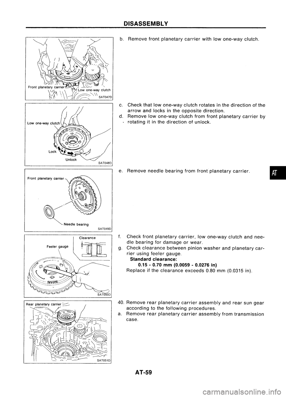
b. Remove frontplanetary carrierwithlowone-way clutch.
c. Check thatlowone-way clutchrotates inthe direction ofthe
arrow andlocks inthe opposite direction.
d. Remove lowone-way clutchfromfront planetary carrierby
rotating itin the direction ofunlock.
e. Remove needlebearing fromfrontplanetary carrier.
•
f. Check frontplanetary carrier,lowone-way clutchandnee-
dle bearing fordamage orwear.
g. Check clearance betweenpinionwasher andplanetary car-
rier using feeler gauge.
Standard clearance:
0.15 -0.70
mm
(0.0059 -0.0276
in)
Replace ifthe clearance exceeds0.80mm(0.0315 in).
40. Remove rearplanetary carrierassembly andrear sungear
according tothe following procedures.
a. Remove rearplanetary carrierassembly fromtransmission
case.
AT-59
Page 61 of 1701
Parkingshaft
SAT064D
SAT702D DISASSEMBL
V
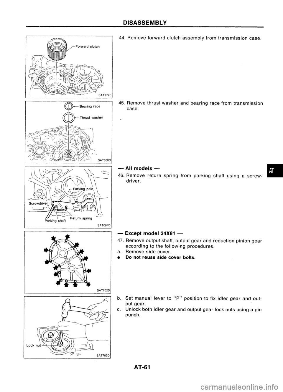
44. Remove forwardclutchassembly fromtransmission case.
45. Remove thrustwasher andbearing racefrom transmission
case.
- All models - •
46. Remove returnspring fromparking shaftusing ascrew-
i
driver.
- Except model34X81-
47. Remove outputshaft,output gearandreduction piniongear
according tothe following procedures.
a. Remove sidecover.
• Donot reuse sidecover bolts.
b. Set manual leverto"p" position tofix idler gear andout-
put gear.
c. Unlock bothidlergear andoutput gearlocknuts using apin
punch.
AT-61
Page 75 of 1701

SAT245EB
Nut
Section Z- Z
Reamer bolt
•
Bolt
symbol
@
@ @@
CID
cD
Bolt length 'T'
13.558.0 40.0 66.033.078.0
~Qmm(in)
(0.531)
(2.283)(1.575)(2.598) (1.299)
(3.071)
Number ofbolts
4
3 611
22
Bolt symbol
@
@ @@
CID
CD
Bolt length" ("
13.558.0 40.0
66.0 33.078.0
~ (0.531)(2.283)
(1.575)(2.598) (1.299)(3.071)
>-,-1
Qmm (in)
Number ofbolts
53 611
22
With
torque converter clutchsolenoid valve
@
@
REPAIR
FORCOMPONENT PARTS
Control ValveAssembly (Cont'd)
2. Disassemble upper,interandlower bodies usingthefollow-
ing procedures.
Bolt length, number andlocation:
Without torqueconverter clutchsolenoid valve
CD
Plain
washer
Section
y- y
Model
34X68
Section Y- Y
@Bolt~
Support plate
f
(E)BOIt~
Support plate~
(f)
Plain
washer
Nut SAT515HB
Model 34X68
a.
Remove bolts@,@and
CB
shown inthe illustration.
b. Remove oilstrainer fromcontrol valveassembly.
AT-75
Page 76 of 1701
Model34X69. 34X70.34X80,34X81 REPAIR
FORCOMPONENT PARTS
Control ValveAssembly (Cont'd)
Model 34X68
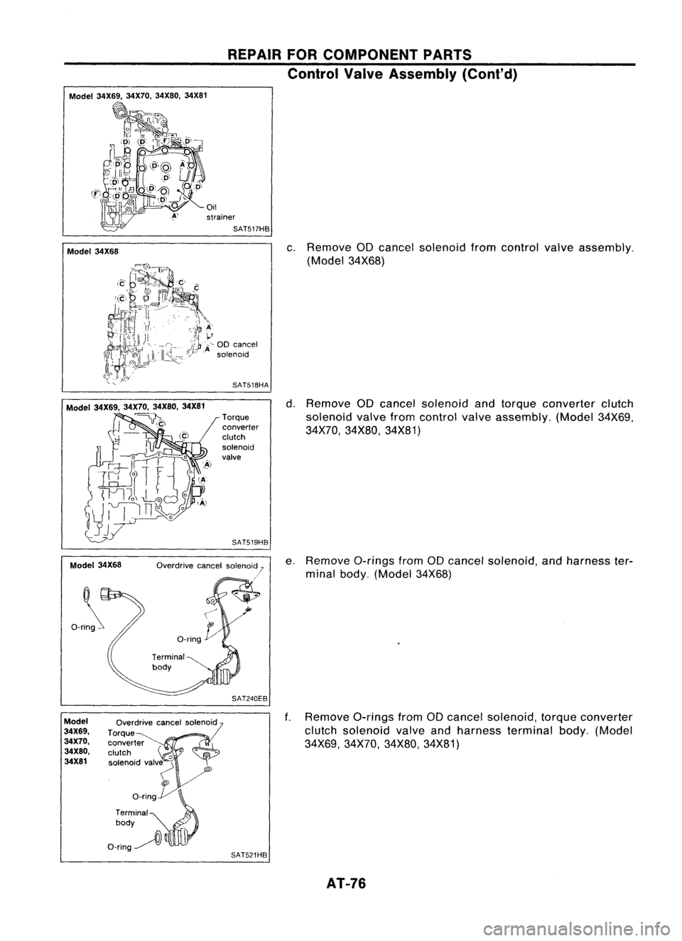
c.
Remove aDcancel solenoid fromcontrol valveassembly.
(Model 34X68)
Model 34X69. 34X70,34X80.34X81
~)
Model 34X68
Ori~
Torque
converter
clutch
solenoid
valve
SAT519HB
SAT240EB
d.
Remove aDcancel solenoid andtorque converter clutch
solenoid valvefromcontrol valveassembly. (Model34X69,
34X70, 34X80, 34X81)
e. Remove a-ringsfromaDcancel solenoid, andharness ter-
minal body. (Model 34X68)
ModeJ
34X69.
34X70.
34X80.
34X81
Overdrive
cancelsolenoid
Torque
converter
clutch
'0
solenoid valv~
"
o_rin~
Terminal
0
body
O-ring~
l\
SAT521HB
f.
Remove a-ringsfromaDcancel solenoid, torqueconverter
clutch solenoid valveandharness terminal body.(Model
34X69, 34X70, 34X80,34X81)
AT-76
Page 79 of 1701
REPAIRFORCOMPONENT PARTS
Control ValveAssembly (Cont'd)
INSPECTION
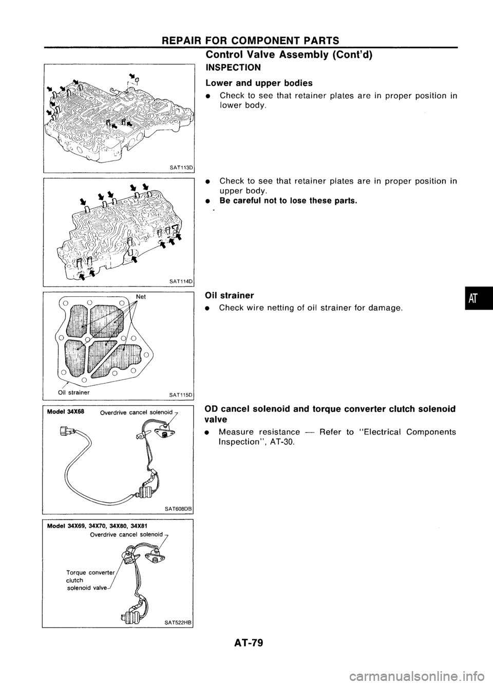
Lower andupper bodies
• Check tosee that retainer platesareinproper position in
lower body.
SAT113D
•Check tosee that retainer platesareinproper position in
upper body.
• Becareful nottolose these parts.
Oil strainer
• Check wirenetting ofoil strainer fordamage.
•
Oil strainer
Model 34X68 SAT115D
Overdrive cancelsolenoid
SAT608DB 00
cancel solenoid andtorque converter clutchsolenoid
valve
• Measure resistance -Refer to"Electrical Components
Inspection", AT-3D.
Model 34X69, 34X70,34X80, 34X81
Overdrive cancelsolenoid
Torque converter
clutch solenoid valve
SAT522HBAT-79
Page 82 of 1701
Lowerseparating
gasket REPAIR
FORCOMPONENT PARTS
Control ValveAssembly (Cont'd)
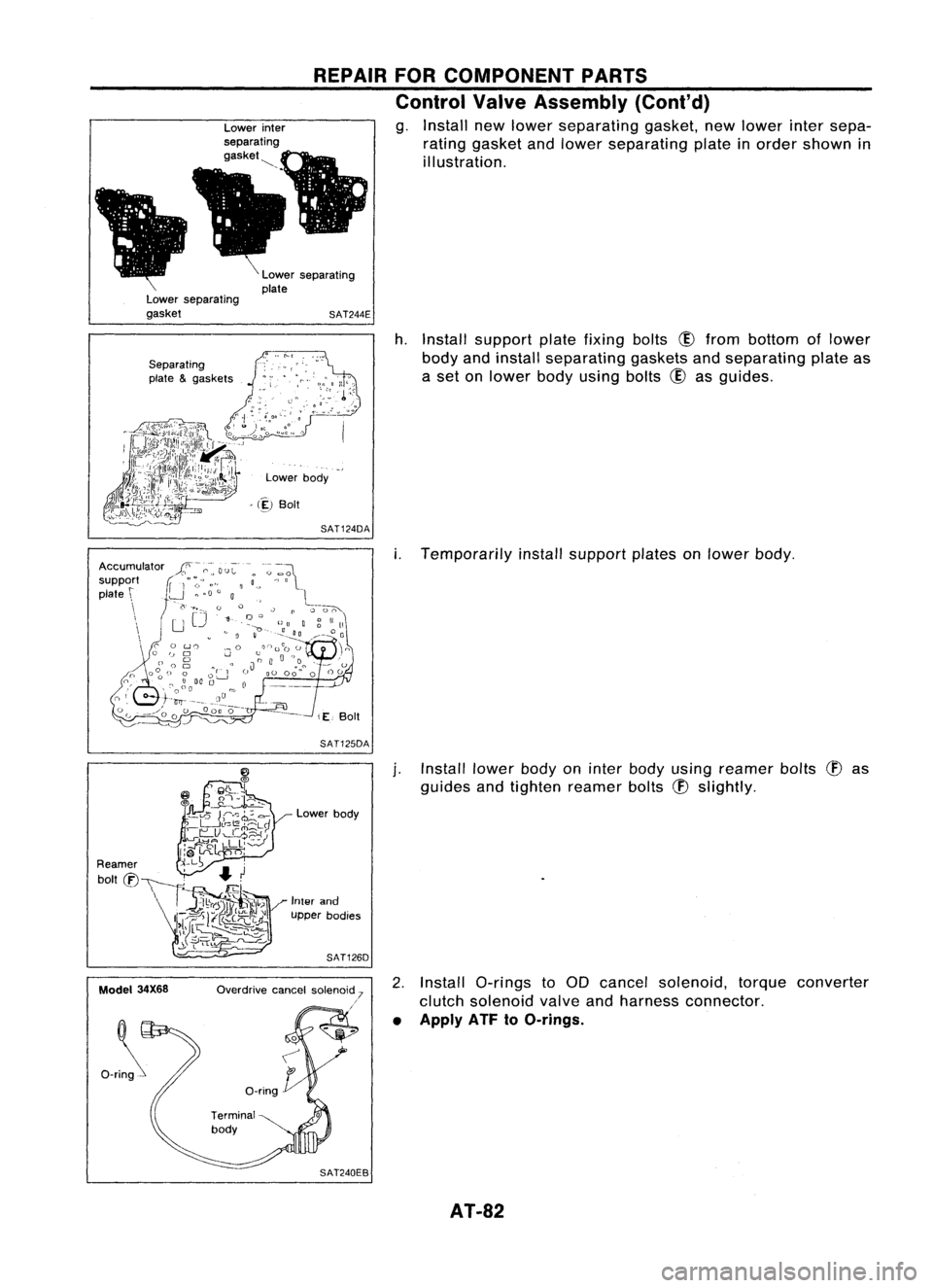
g. Install newlower separating gasket,newlower intersepa-
rating gasket andlower separating plateinorder shown in
illustration.
Lower separating
plate
SAT244E
Separating
plate &gaskets
Lowerbody
> (~)
Boit
SAT124DA
h.
Install support platefixing bolts
CID
from bottom oflower
body andinstall separating gasketsandseparating plateas
a set onlower bodyusing bolts
CID
asguides.
SAT125DA
i.
Temporarily installsupport platesonlower body.
Model 34X68 Lower
body
Inter and
upper bodies
SAT126D
Overdrive cancelsolenoid 7
.'
j.
Install lowerbodyoninter body using reamer bolts
(f)
as
guides andtighten reamer bolts
(f)
slightly.
2. Install a-rings toaD cancel solenoid, torqueconverter
clutch solenoid valveandharness connector.
• Apply ATF
toO-rings.
AT-82
Page 83 of 1701
REPAIRFORCOMPONENT PARTS
Control ValveAssembly (Cont'd)
Model
34X69, 34X70,
34X80, 34X81 Overdrive
cancelsolenoid
Torque~ converter
clutch
'0
solenoid valv~
'"
o_rin~
Terminal
0
body
O-ring~
l\
SAT521HB
Section Z- Z
Reamer bolt
Model
34X68
•
Bolt
symbol
@
@
@
@
(!)
ffi
Bolt length "C"
13.558.0 40.0 66.0
33.078.0
~ Q
mm(in)
(0.531)
(2.283)(1.575) (2.598)(1.299)
(3.071)
Number ofbolts
4
3611
22
3.4 -
4.4 7-9
Tightening torque
7-9 (0.7 -0.9, 61-78) (0.35
-(0.7 -
N'm (kg-m, in-Ib)
0.45,
0.9,61
30.4 - -78)
39.1)
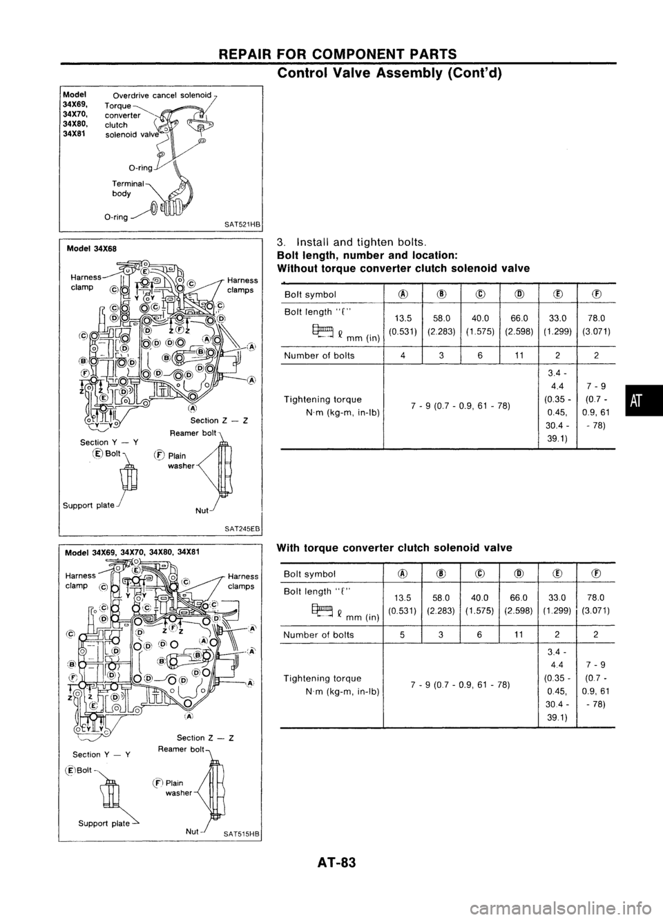
3.
Install andtighten bolts.
Bolt length, number andlocation:
Without torqueconverter clutchsolenoid valve
/
Nut
(:E)
Plain
washer
Section
y- y
@Bolt~
Support plate
r
SAT245EB
Section
y- y
Section
Z- Z
Reamer bolt With
torque converter clutchsolenoid valve
Bolt symbol
@
@
@
@
(!)
ffi
Bolt length "C"
13.558.0
40.0 66.033.0
78.0
~ Q
mm (in)
(0.531)
(2.283)
(1.575) (2.598)(1.299)
(3.071)
Number ofbolts
536
11 2
2
3.4 -
4.4 7-9
Tightening torque
7-9 (0.7 -0.9, 61-78) (0.35
-(0.7 -
N'm (kg-m, in-Ib)
0.45,
0.9,61
30.4 --
78)
39.1)
(ElBolt -
. S"PP~
en
Plain
washer
AT-83
Page 84 of 1701
REPAIRFORCOMPONENT PARTS
Control ValveAssembly (Cont'd)
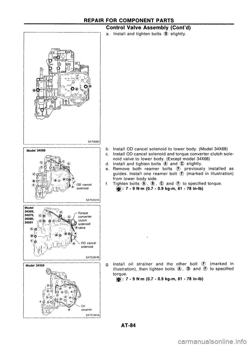
a. Install andtighten bolts
@
slightly.
SAT609D
Model 34X68
b.
Install ODcancel solenoid tolower body.(Model 34X68)
c. Install ODcancel solenoid andtorque converter clutchsole-
noid valve tolower body.(Except model34X68)
d. Install andtighten bolts
@
and
@
slightly.
e. Remove bothreamer bolts
(f)
previously installedas
guides. Installonereamer bolt
(f)
(marked inillustration)
from lower bodyside.
f.
Tighten bolts
@,
@,
@
and
(f)
tospecified torque.
~: 7-
9 N'm (0.7-0.9 kg-m, 61-78 in-Ib)
SAT525HA
00 cancel
solenoid
SAT526HB
g.Install oilstrainer andtheother bolt
CB
(marked in
illustration), thentighten bolts
@,
@
and
CB
tospecified
torque.
~: 7-
9 N'm (0.7-0.9 kg-m, 61-78 in-Ib)
Oil
strainer
SAT516HA
AT-84
Page 92 of 1701
REPAIRFORCOMPONENT PARTS
Control ValveLower Body(Cont'd)
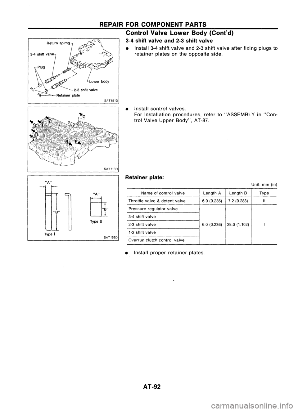
3-4 shift valve and2-3shift valve
• Install 3-4shift valve and2-3shift valve afterfixing plugsto
retainer platesonthe opposite side.
SAT151D
•Install control valves.
For installation procedures, referto"ASSEMBLY in"Con-
trol Valve Upper Body", AT-8?
SAT113D
"A"
"B"
U
Type I
"A"
Eli
Type II
SAT153D Retainer
plate:
Unit:mm(in)
Name ofcontrol
valve
Length
ALength 8 Type
Throttle
valve
&
detent
valve 6.0(0.236) 7.2(0.283)
1/
Pressure regulator
valve
3-4
shift
valve
2-3
shift valve
6.0(0.236) 28.0(1.102)
I
1-2
shift valve
Overrun
clutchcontrol
valve
• Install proper retainer plates.
AT-92
Page 93 of 1701
REPAIRFORCOMPONENT PARTS
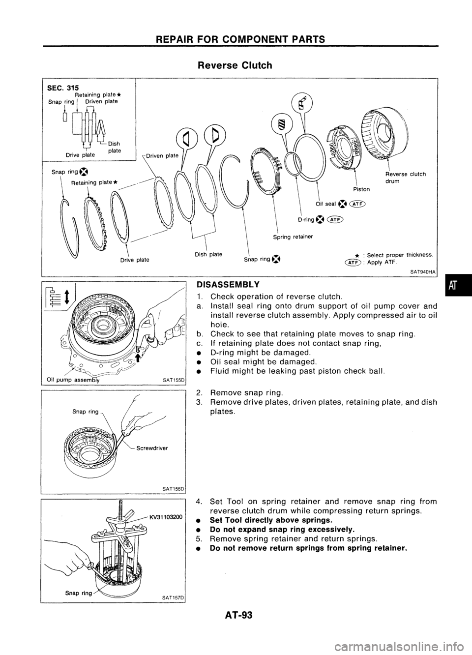
Reverse Clutch
Piston
* :
Select proper thickness.
~. ApplyATF.
Oil
seal~@D
D-ring~
@:>
Snap ring~
Dish
plate
Drive plate
SEC.
315
Retaining plate
*
Snap ring
I
Driven plate
Snap ring~
SAT940HA
DISASSEMBLY •
1. Check operation ofreverse clutch.
a. Install sealringonto drum support ofoil pump cover and
install reverse clutchassembly. Applycompressed airtooil
hole.
b. Check tosee that retaining platemoves tosnap ring.
c. Ifretaining platedoesnotcontact snapring,
• D-ring mightbedamaged.
• Oilseal might bedamaged.
• Fluid might beleaking pastpiston checkball.
2. Remove snapring.
3. Remove driveplates, drivenplates, retaining plate,anddish
plates.
SAT156D
KV31103200
SAT157D
4.
Set Tool onspring retainer andremove snapringfrom
reverse clutchdrumwhilecompressing returnsprings.
• Set Tool directly abovesprings.
• Donot expand snapringexcessively.
5. Remove springretainer andreturn springs.
• Donot remove returnsprings fromspring retainer.
AT-93