radio antenna NISSAN ALMERA N15 1995 Service Manual
[x] Cancel search | Manufacturer: NISSAN, Model Year: 1995, Model line: ALMERA N15, Model: NISSAN ALMERA N15 1995Pages: 1701, PDF Size: 82.27 MB
Page 374 of 1701

CONTENTS(Conl'd.)
Front FogLamp Aiming Adjustment.. 101
Rear FogLamp/Wiring Diagram-R/FOG -102
Turn Signal andHazard Warning Lamps/
Schematic 106
Turn Signal andHazard Warning
Lamps/Wiring Diagram-TURN - 107
Turn Signal andHazard Warning
Lamps/Trouble Diagnoses 113
Combination FlasherUnitCheck 113
Bulb Specifications 114
INTERIOR LAMP 115
Illumination/Schematic 115
Illumination/Wiring Diagram-ILL - 116
Interior, Spot,Trunk Room andLuggage
Room Lamps/Wiring Diagram-INT/L - 122
Bulb Specifications 126
METER ANDGAUGES 127
Combination Meter 127
Speedometer, Tachometer,Temp.andFuel
Gauges/Wiring Diagram-METER - 129
Inspection/Fuel GaugeandWater
Temperature Gauge 133
Inspection/Tachometer 134
Inspection/Speedometer andVehicle Speed
Sensor 135
Fuel Tank Gauge UnitCheck 137
Thermal Transmitter Check 137
Vehicle SpeedSensor SignalCheck 137
WARNING LAMPSANDBUZZER 138
Warning Lamps/Schematic 138
Warning Lamps/Wiring Diagram-WARN -139
Oil Pressure SwitchCheck 151
Fuel Warning LampSensor Check 151
Diode Check 151
Warning BuzzerUnit... 151
Warning Buzzer/System Description 152
Warning Buzzer/Wiring Diagram
- BUZZER - 154
Components Inspection-Warning Buzzer 157
WIPER ANDWASHER 160
Front Wiper andWasher/System Description160
Front Wiper andWasher/Wiring Diagram
- WIPER - 162
Front Wiper Amplifier Check 166
Front Wiper Installation andAdjustment.. 166
Front Wiper Linkage 167
Front Washer NozzleAdjustment... 168
Front Washer TubeLayout 168
Rear Wiper andWasher/System Description169Rear
Wiper andWasher/Wiring Diagram
- WIP/R - 171
Rear Wiper Amplifier Check 175
Rear Wiper Installation andAdjustment.. 175
Rear Washer NozzleAdjustment 175
Rear Washer TubeLayout.. 176
Check Valve(forrear washer) 176
Headlamp WiperandWasher/Wiring Diagram
- HLC - 177
Headlamp WiperMotorCheck 179
Headlamp WiperInstallation 179
Headlamp WasherTubeLayout.. 179
Check Valve(Forheadlamp washer) 179
POWER WINDOW 180
System Description 180
Schematic 183
Wiring Diagram -WINDOW - 185
Trouble Diagnoses 197
POWER DOORLOCK 198
System Description 198
Schematic 200
Wiring Diagram -D/LOCK - 202
Trouble Diagnoses -Type 1(For Europe and
Austral ia) 212
Trouble Diagnoses -Type 2(Except for
Europe andAustralia) 216
POWER DOORMIRROR 220
Wiring Diagram -MIRROR - 220
ELECTRIC SUNROOF 224
Wiring Diagram -SROOF - 224
HORN, CIGARETTE LIGHTERANDCLOCK 226
Wiring Diagram -HORN - 226
REAR WINDOW DEFOGGER ANDDOOR
MIRROR DEFOGGER 230
System Description (Formodels withdaytime
light system) 230
Wirin.g Diagram -DEF - 231
Filament Check 235
Fi lament Repai
r
236
AUDIO ANDANTENNA 237
Audio/System Description 237
Wiring Diagram -AUDIO - 238
Radio FuseCheck 243
Location ofAntenna 243
Antenna RodReplacement.. 243
HEATED SEAT 245
Wiring Diagram -H/SEAT - 245
NATS (Nissan Anti-Theft System) 247
System Description 247
System Composition 247
Page 609 of 1701
![NISSAN ALMERA N15 1995 Service Manual AUDIOANDANTENNA
Audio/System Description
Refer toOwner's Manualforaudio system operating instructions.
Power issupplied atall times
• through 7.5Afuse(No.
[2]],
located inthe fuse block)
• to](/img/5/57349/w960_57349-608.png "NISSAN ALMERA N15 1995 Service Manual AUDIOANDANTENNA
Audio/System Description
Refer toOwner's Manualforaudio system operating instructions.
Power issupplied atall times
• through 7.5Afuse(No.
[2]],
located inthe fuse block)
• to")
AUDIOANDANTENNA
Audio/System Description
Refer toOwner's Manualforaudio system operating instructions.
Power issupplied atall times
• through 7.5Afuse(No.
[2]],
located inthe fuse block)
• toradio terminal
@,
and
• tocompact diskdeck terminal
@.
With theignition switchinthe ACC orON position, powerissupplied
• through 15Afuse (No.
[j]],
located inthe fuse block)
• toradio terminal
@),
and
• tocompact diskdeck terminal
@.
Ground issupplied throughthecase ofthe radio.
When theradio power knobispushed tothe ON position, audiosignals aresupplied
• through radioterminals 1,2, 3,
4,
13,
)4,
15and 16
• tothe door, pillarandrear speakers.
EL-237
•
Page 610 of 1701
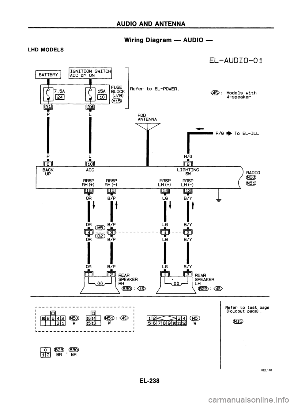
AUDIOANDANTENNA
Wiring Diagram -AUDIO -
LHD MODELS
EL-AUDIO-01
RADIO
Q3W
Models
with
4-speaker
ROD
ANTENNA
~~gEK
RefertoEL-POWER.
(JIB)
~
L
~
ACC
....
~ AIG~To EL-ILL
RIG
m
LIGHTING
SW
RRSP RRSP RRSPRRSP
RH
(+)
RH(-) LH
(+)
LH(-)
l!JjJJ ~ ~~
OR B/P LGB/Y
I. It I.It
OR
IciJ~ -~ -
tiJ~ -------- - --
~ciJ~ ---
~ciJl
OR ~ B/P LGB/Y
I I II
P
m
BACK
UP
ORB/P
JL:QQ~EAA
SPEAKER
RH
~:@
r-------------------------,
I
I
~:@I
W
I
I
I
L
~
&~@)
5 6
TII;uo
1112W
Refer
tolast page
(Foldout page).
[Q]~~
I]lg]
BR•BR
HEL140
EL-238
Page 611 of 1701
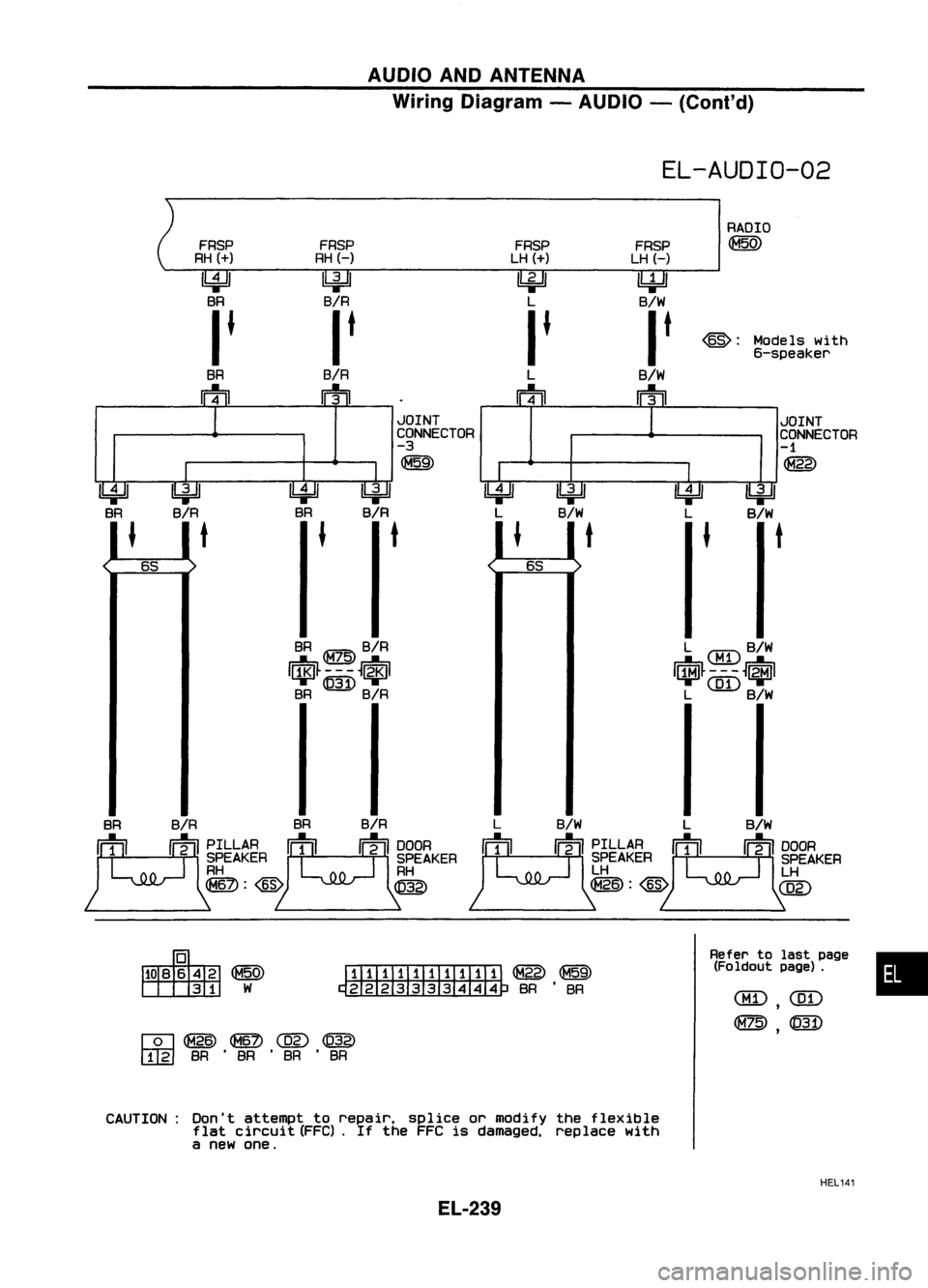
AUDIOANDANTENNA
Wiring Diagram -AUDIO -(Cont'd)
EL-AUDIO-02
•
Models
with
6-speaker
JOINT
CONNECTOR
-1
@)
I'=idJ
B/W
t
RADIO
~
Refer tolast page
(Foldout page).
@:
U4=J1
L
FRSP
LHH
~
B/W
I
t
B/W
rn
I'=idJ
B/W
t
B/W LB/W
m2
PILLAR
t
1
\Q
4
2-
I
DOOR
SPEAKER SPEAKER
LH LH
~:@
@)
FRSP
LH
(+)
~
L
IJ
L
rrtn
~
L
1
I I
I"IIJJIIIITIITi
@)
~BR'BR
FRSP
FRSP
RH
(+)
RHH
~ ~
BR B/R
I
J It
BR B/R
rrtn
rn
JOINT
CONNECTOR
-3
~
4=Jl
~
~
B/R BR
B/R
t
f
t
B/R BRB/R
~ PILLAR J!1
\Q
4
2-
I
DOOR
11211
SPEAKER SPEAKER
RH RH
~:@ ~
[Q]~~(@~
[IIg]
BR'BR 'BR 'BR
CAUTION: Don'tattempt torepair, spliceormodify theflexible
flat circuit (FFC).If the FFC isdamaged, replacewith
a new one.
HEL141
EL-239
Page 612 of 1701
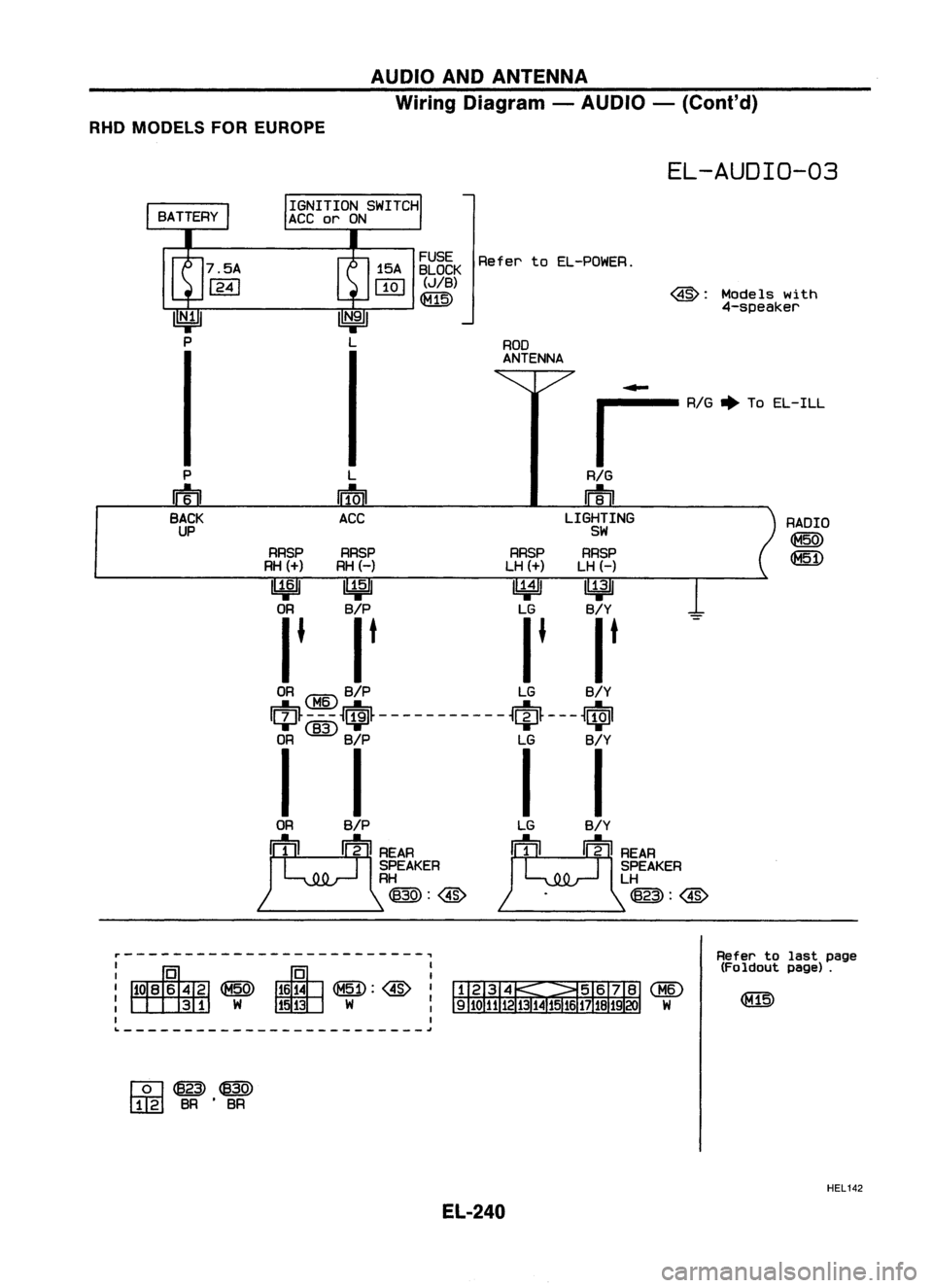
AUDIOANDANTENNA
Wiring Diagram -AUDIO -(Conl'd)
RHO MODELS FOREUROPE
EL-AUDIO-03
RADIO
@
(8[D
Models
with
4-speaker
@:
ROD
ANTENNA
~~5~K
RefertoEL-POWER.
(JIB)
(8Th)
L
rrfcrn
ACC
....
,......... AlG~ToEL-ILL
RIG
m
LIGHTING
SW
RRSP RRSP RRSPRRSP
RH
(+)
RH(-) LH
(+)
LH(-)
~ ~ ~~
OR B/P LGB/Y
I • I
t
I• I
t
OR
<:MID
B/P LGB/Y
I~~
-i:-~.~ -------- -- -
~$~ ---
~$I
OR
@)
B/P LGB/Y
I I II
P
m
BACK
UP
ORB/P
J!oo~~AA
SPEAKER
RH
@:@
~-------------------------~
I
I
(8[D:@
I
W :
I I
~-------------------------j
W
Refer
tolast page
(Foldout page).
[Q]~@)
[!gJ
BR•BR
HEL142
EL-240
Page 613 of 1701
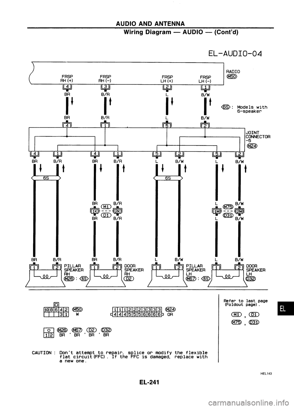
AUDIOANDANTENNA
Wiring Diagram -AUDIO -(Cont'd)
EL-AUDIO-04
FRSP
RH
(+)
~
BR
I
J
BR
m FRSP
RHH
Ibi=ll
B/R
I
t
B/R
m FRSP
LH
(+)
~
L
I
J
L
IFtil
FRSP
LH (-)
IbjdJ
B/W
I
t
B/W
ri1=TI
RADIO
@)
@:
Models with
6-speaker
•
JOINT
CONNECTOR
-5
@)
~
B/W
t
~
L
L ~B/W
I$~---~.I
L ~B/W
~
B/W
t
Refertolast page
(Fo ldout page).
~
L
L B/W LB/W
~~ ~PILLAA
[tooljrom
111
II
11-2
IISPEAKER II1II II2 IISPEAKER
LH LH
~:@
@
l6i=!J
B/R
t
~~
~OR
l!4=U
BR
J
l6i=!J
B/R
t
1
1
I
I
I
I
[Q]~~@)~
[I[g]
BR•BR •BR •BR
CAUTION: Don'tattempt torepair. spliceormodify theflexible
flat circuit (FFC).If the FFC isdamaged. replacewith
a new one.
HEL143
EL-241
Page 614 of 1701
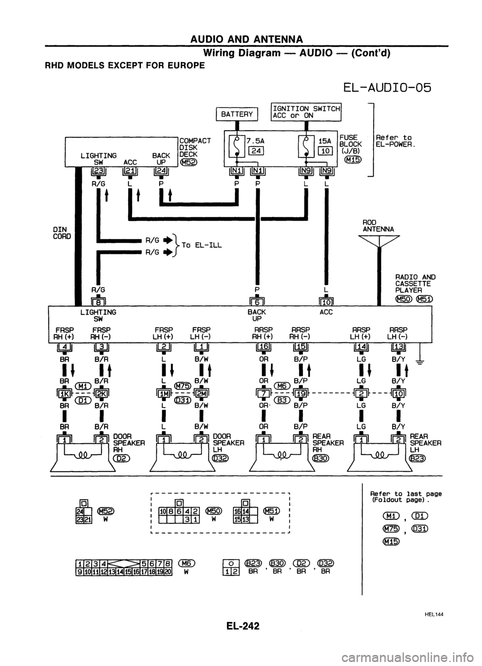
AUDIOANDANTENNA
Wiring Diagram -AUDIO -(Cont'd)
RHD MODELS EXCEPTFOREUROPE
EL-AUDIO-05
RADIOAND
CASSETTE
PLAYER
~ (fID)
RRSP
LH (-)
~
B/Y
-
ROD
ANTENNA
RRSP
LH (+)
~
LG
FUSE
Referto
BLOCK EL-POWER.
(JIB)
~
L
IffoD
ACC
RRSP
RH (-)
~
B/P
COMPACT
DISK
BACK DECK
UP ~
1
2•4
1 ~~
P P
I_t __ I
LIGHTING
SW
1
2
:1
RIG
t
FRSP
RH
(+)
I!4=Jl
BR
DIN
CORD
~~
~W
r---------------------~
I
I
~I
W :
I
Refer
tolast page
(Foldout page).
[Q] ~
@
C02)
@
[IIg]
BR.BR .BR .BR
HEL144
EL-242
Page 615 of 1701
AUDIOANDANTENNA
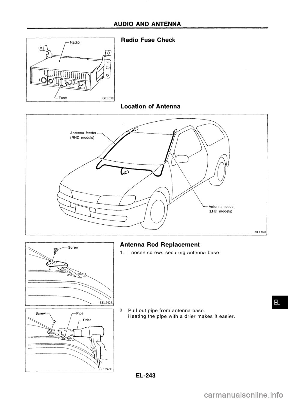
Antenna feeder
(RHO models) Radio
FuseCheck
Location ofAntenna
Antennafeeder
(LHO models)
Antenna RodReplacement
1. Loosen screwssecuring antennabase.
2. Pullout pipefrom antenna base.
Heating thepipe withadrier makes
it
easier.
EL-243 GEL020
•
Page 727 of 1701

PRECAUTIONSANDPREPARATION
Engine Fuel
&
Emission ControlSystem
I
GA, SR
I
BATTERY • Always usea12 volt battery aspower
source.
• Do not attempt todisconnect battery
cables whileengine isrunning.
INJECTOR • Do not disconnect injectorharness
connectors withengine running.
• Do not apply battery powerdirectly to
injectors.
ECCS PARTS HANDLING
• Handle massairflow sensor carefully to
avoid damage.
• Do not disassemble massairflow
sensor.
• Do not clean massairflow sensor with
any type ofdetergent.
• Do not disassemble IACV-AACvalve.
• Even aslight leakinthe airintake
system cancause serious problems.
• Do not shock orjar the camshaft
position sensor. ECM
• Do not disassembly EGM(EGGS control
module).
• Do not turn diagnosis modeselector
forcibly.
• Ifabattery terminal isdisconnected,
the memory willreturn tothe ECM
value.
The ECM willnow start toself-control
at its initial value. Engine operation can
vary slightly whentheterminal is
disconnected. However,thisisnot an
indication ofaproblem. Donot replace
parts because ofaslight variation.
WHEN STARTING
• Do not depress accelerator pedalwhen
starting.
• Immediately afterstarting, donot revup
engine unnecessarily .
• Do not revupengine justprior to
shutdown.
EC-8 WIRELESS
EQUIPMENT
• When installing C.B.hamradio ora
mobile phone, besure toobserve the
following asitmay adversely affect
electronic controlsystems depending
on itsinstallation location.
1) Keep theantenna asfar aspossible
away fromtheEGM.
2) Keep theantenna feederlinemore than
20 em (7.9 in)away fromtheharness
of electronic controls.
Do not letthem runparallel foralong
distance.
3) Adjust theantenna andfeeder lineso
that thestanding-wave ratiocanbe
kept smaller.
4) Be sure toground theradio tovehicle
body.
FUEL PUMP
• Do not operate fuelpump whenthere
is no fuel inlines.
• Tighten fuelhose clamps tothe
specified torque.
ECCS HARNESS HANDLING
• Securely connectEGGSharness
connectors.
A poor connection cancause an
extremely high(surge) voltage to
develop incoil and condenser, thus
resulting indamage toICs .
• Keep ECGS harness atleast 10em (3.9
in) away fromadjacent harnesses, to
prevent anEGGS system malfunction
due toreceiving externalnoise,
degraded operation ofIGs, etc.
• Keep EGCS partsandharnesses dry.
• Before removing parts,turnoffignition
switch andthen disconnect battery
ground cable.
SEF320R