engine wiring NISSAN ALMERA N15 1995 Owner's Manual
[x] Cancel search | Manufacturer: NISSAN, Model Year: 1995, Model line: ALMERA N15, Model: NISSAN ALMERA N15 1995Pages: 1701, PDF Size: 82.27 MB
Page 511 of 1701
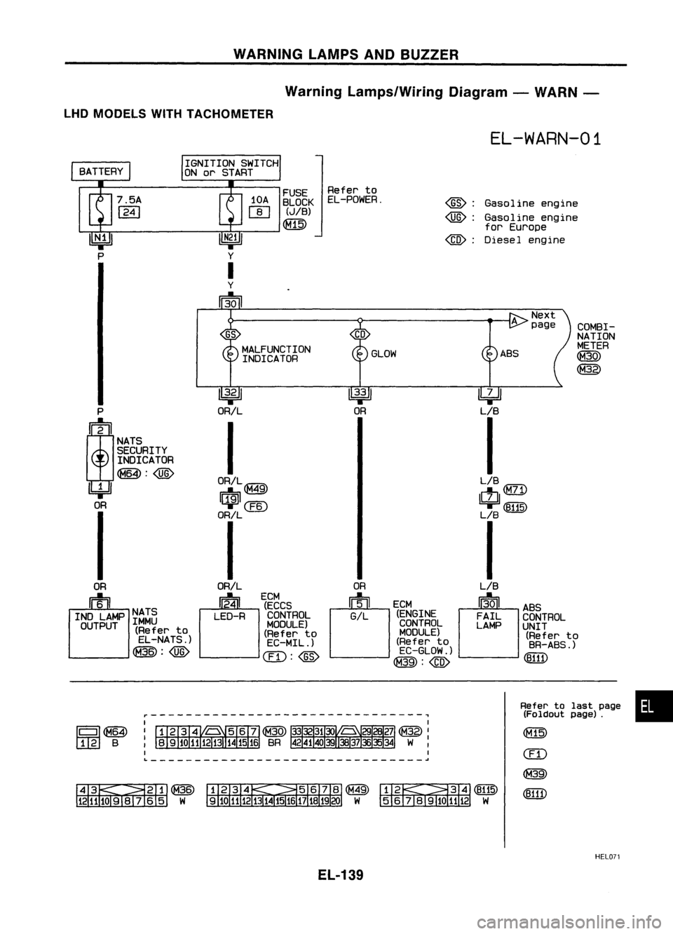
WARNINGLAMPSANDBUZZER
Warning Lamps/Wiring Diagram-WARN -
LHD MODELS WITHTACHOMETER
EL-WARN-01
Gasoline engine
Gasoline engine
for Europe
Diesel engine
@:
@):
@:
FUSE
Referto
10A BLOCK EL-POWER.
rn
(JIB)
Qill)
IGNITION
SWITCH
ON orSTART
COMBI-
GS
NATION
MALFUNCTION METER
INDICATOR GLOW
ABS
~
@)
~ ~~
P ORIL OR
LIB
;
I
I
NATS
SECURITY
INDICATOR
~:@)
ORIL@ LIB
IbjJ
rrf9il
49
ctJ
(M71)
OR
~@
'T
(8115)
ORIL LB
I I
OR ORIL OR
LIB
m
~
ECM
[~JCM
13-01
u'ECCS
ABS
INO LAMP NATS
LEO-RCONTROL GIL
(ENGINE
FAILCONTROL
OUTPUT IMMU
MODULE)CONTROL
LAMPUNIT
(Refer to
(Referto MODULE)
(Referto
EL-NATS.) EC-MIL.) (Refer
to
BR-ABS.)
~:@)
CIT):@
EC-GLOW.)
(8111)
@:@)
r-------------------------------,
IIIII~
1 2 B
~~@
1211J09lv 6
5
W
Refer
tolast page •
(Foldout page).
&~~
5
6j819101112 W
HELD?1
EL-139
Page 512 of 1701

WARNINGLAMPSANDBUZZER
Warning Lamps/Wiring Diagram-WARN -
(Cont'd)
~: Gasoline engine
~: Diesel engine
@:
@:
Models
withdual air
bag system
Models withsingle
air bagsystem
EL-WARN-02
COMBI-
NATION
METER
@
~
OIL
PRESSURE
SWITCH
~
DIL
~
P/L
I
~CMID
~m
P/L
~~
t
I
P
/L
iE='iA'\
P
/L
rE'\\
~~ ~~
~ ~
P/L ~ P/L~
I
o~
I
P/L
m
..... _-
HIGH
~
G/A
G/R
Q:ID
~@
G/R
I
G/R
m
FUEL
TANK
GAUGE
_ UNIT
HIGH (B18)
~
in
B B B
t.J
J
~ ~
AIR
BAG FUEL
~
B/A
B/R
~
SPIRAL
CABLE
~
BR/W
I
o'
f
BR/W
tUi5'"\
~~ ~~
BR/W
I
BR/W
meW)
BR/W~
~~
~CW
BR/W
Preceding
A
page
BR/W
I
I~
I
AIR BAG
c:J
AIRBAG
W/L DIAGNOSIS W/LDIAGNOSIS
SENSOR SENSOR
UNIT UNIT
(Refer to (Referto
RS-SRS .) RS-SRS.)
aD:@
@:@
~~Q:ID5 6
J8I9IDH
12W
Refer
tolast page
(Foldout page).
CHID
(E1OD
~~
~B ~~
~B
HELon
EL-140
Page 513 of 1701
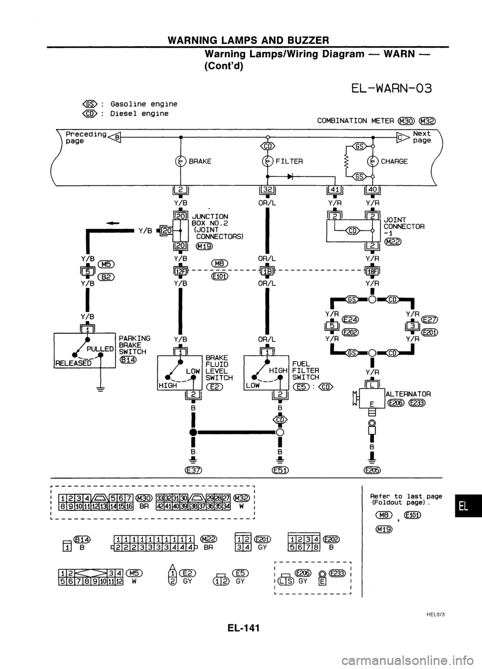
WARNINGLAMPSANDBUZZER
Warning Lamps/Wiring Diagram-WARN -
(Cont'd)
EL-WARN-03
~: Gasoline engine
~: Diesel engine
COMBINATIONMETER~~
•
Refer
tolast page
(Foldout page).
CHID
(E10
1)
(M19)
FILTER
~~
IIDID:IID
B
~~
tml
GY
BRAKE
....
_-
HIGH
ITIillJIIIIIIII ~
~BR
4=U
~
llWJ
Y
IB
ORILY
IR
Y
IR
~20 JUN~TION
I
~2
m
JOINT
~ BOXNO.2
r
Y
IB
~O (JOINT
CD
~ONNECTOR
CONNECTORS) ~
I
2..a
I
~@
Y/B
CBID
ORIL Y/R
I~I
@g)
I$~-- -CEl0l)- -- --
~$~ ----- --- -- ----
~ufJl
Y
IB
Y
IB
ORIL Y
IR
I
II~~~
Y/B Y/R~ Y/R@Z)
m1 I~II~I
'=r ~ '=rCE2Q1)
PARKING Y
IR
Y
IR
BRAKE •_ _.
SWITCH
~O~
~ BRAKE
I
FLUID FUEL
LOW LEVEL HIGHFILTER Y/R
~~~~CH LOW~-- ~~~~~H
@)
rn11:"1
II 2 II II2 II ALTERNATOR
T T
E
@@@)
f---t, ~
B B B
..... ..... -l
(E205)
Preceding
B
page
F.=I~
L.!J
B
....
_-
RELEASED
~-------------------------------~
L ~
Ii\Clli
tg)
GY
@
GY
r-----------.,
I I
I
,.hh
(E206) ~(E233)
I
Ilh,@
GY~
1
I I
L. -'
HEL073
EL-141
Page 515 of 1701
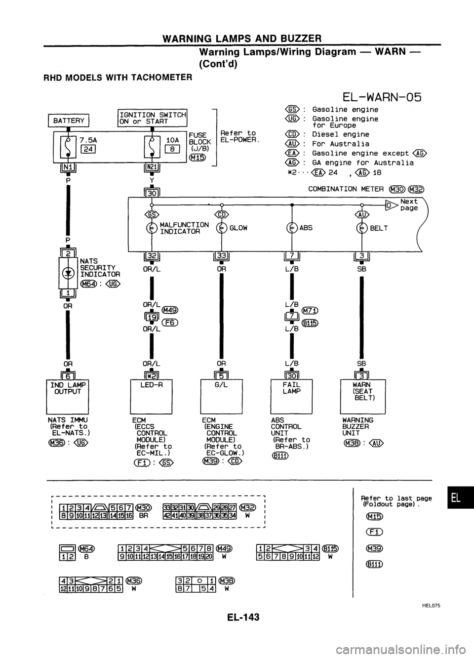
WARNINGLAMPSANDBUZZER
Warning Lamps/Wiring Diagram-WARN -
(Conl'd)
RHD MODELS WITHTACHOMETER
•
Refer
tolast page
(Foldout page).
(f1lli)
(ED
@
(8111)
WARNING
BUZZER
UNIT
@:@
~
SB
SB
u1il
r
WARN
(SEAT BELT)
EL-WARN-05
~: Gasoline engine
~: Gasoline engine
for Europe
~: Diesel engine
~: ForAustralia
~: Gasoline engineexcept~
~: GAengine forAustralia
*2"'@24 ,~1B
COMSINA TIONMETER
@)
@)
~~
J8191Q
1112
W
FUSE
Referto
BLOCK EL-POWER.
(JIB)
1 2 B
r---------------------------------,
GS
MALFUNCTION GLOWASS
INDICATOR
P
!
~
~
~
NATS
SECURITY ORIL OR
LIB
INDICATOR
I
I
~:@
'4=Jl
OR ORIL~ LIB
QQD
I$I@
ctl
71
I,
I
ORIL L
B
I I
OR ORILOR
LIB
n=til
0
U
13.0
I
IND LAMP LED-R
GILFAIL
OUTPUT LAMP
NATS IMMU
ECM ECM
ABS
(Refer to
(ECCS (ENGINECONTROL
EL-NATS.) CONTROLCONTROL
UNIT
@:~
MODULE)
MODULE)(Refer
to
(Refer to (Refer
to BR-ABS.)
EC-MIL.) EC-GLOW.)
(8111)
@: ~ @:@
~~@
12111091V
65 W
~@
~W
HEL075
EL-143
Page 517 of 1701
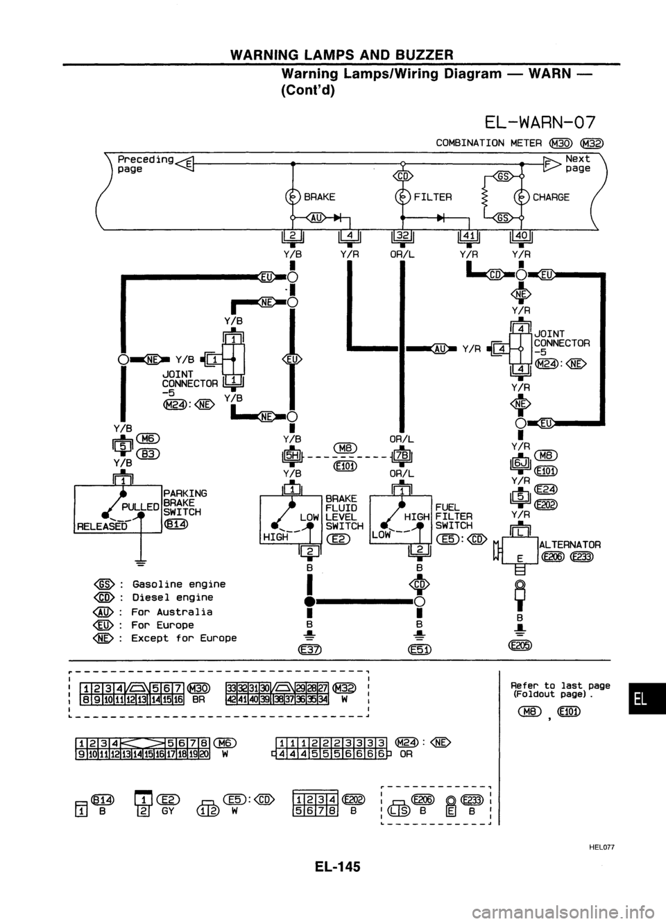
WARNINGLAMPSANDBUZZER
Warning Lamps/Wiring Diagram-WARN -
(ConI' d)
EL-WARN-07
•
Refer
tolast page
(Foldout page).
<:BID
FILTER
8RAKE
Gasoline engine
Diesel engine
For Australia
For Europe
Except forEurope
Preceding
E
page
@:
@:
@:
@:
@:
lbjJ
~~~
V8 ~A
Yffl
VR
EU ~
~
EU
.1 ~
~O ~
I -
Y/R
Y/8 ~
ffi
~4JOINT
" __ II~ Y
IR ~
~gNNECTOR
O~
Y
18
.Ji1
EU
IU"'i'A\A'i"E'..
~ IWI~:~
JOINT
=r'
Y/R
~:@
Y/8
4
1..«-0 T
Y/8
I ()
EU
1$1
@
Y18
CHID
ORIL Y'R
@)
It~----------i$1
~~6J(][)
Y/8 $100~
-1
ffl
WL ~
11111
W
m
Y/R
PARKING 18RAKE 1 I~I~
PULLED ~~~~~H FLUIDFUEL~
LOW LEVEL HIGHFILTER Y
IR
RELEASED ~ SWITCH
'-- LOW'--SWITCH
rn':' I
HIGH
@
@:@
ALTERNATOR
I4J ~
E
CE2(6) ~
8 8
11---1; ~
I I
8
8 8...
-!- .....
=
~ CE51)CE205)
r---------------------------------~
~~:@
~ OR
F.=l~
L!.J
8
m@
~@:@)
'IN
GY
u.w
W
~------------.,
ffi2i3T4l ~:~
CE2(6) ~~ :
rn::tilllID
8
I
\b.@
BE8
I
I I
L
.I
HELD??
EL-145
Page 536 of 1701
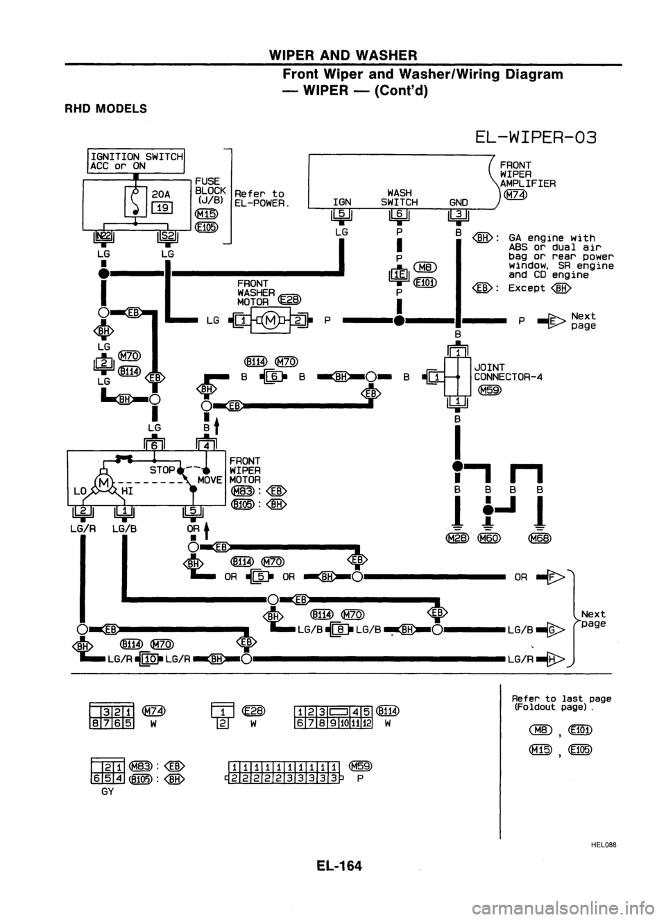
WIPERANDWASHER
Front Wiper andWasher/Wiring Diagram
- WIPER -(Cont'd)
RHD MODELS
EL-WIPER-03
Next
page
P
-I'E-
Next
~ page
OR
-€>
GA
engine with
ABS ordual air
bag orrear power
window, SRengine
and CDengine
Except
@
@:
GNO
lbjJJ
B
@:
B
~1
JOINT
~ CONNECTOR-4
~
~ B
I
I'
n
B BB 8
It-ll
~ (M60) ~
WASH
SWITCH
~ P
I
P
1$1 ~~:~
P
I
---'.---11---
@B)@
B~B~O-B
i>
FRONT
WASHER~B
MOTOR
'l:5.!3'
~P
FUSE
BLOCK Referto
(JIB) EL-POWER. IGN
00
I
S.21 LG
~
LG
•
.1
.
I
o
•
LG
LfJ@
1ki=Jl~
EB
LG
~O
I
LG
Iftu
IbjJl
0:
t
O~ ..-
<1ftp ~
@)
~ OR~ OR
~O--------
.. --------lO~ ..------.-
<1ftp ~
@)
<0>
O~
:L
~LG/B~ .LG/B~O----LG/B ~
~ ~@) ~ ,
';"LG/R-MO.LG/R~O---------------LG/R-e>
~@>
rn:rz:tm:I
W
~~:@
m
ITIillIIIIIIIIT
~
~P
Refer
tolast page
(Foldout page).
HEL088
EL-164
Page 603 of 1701
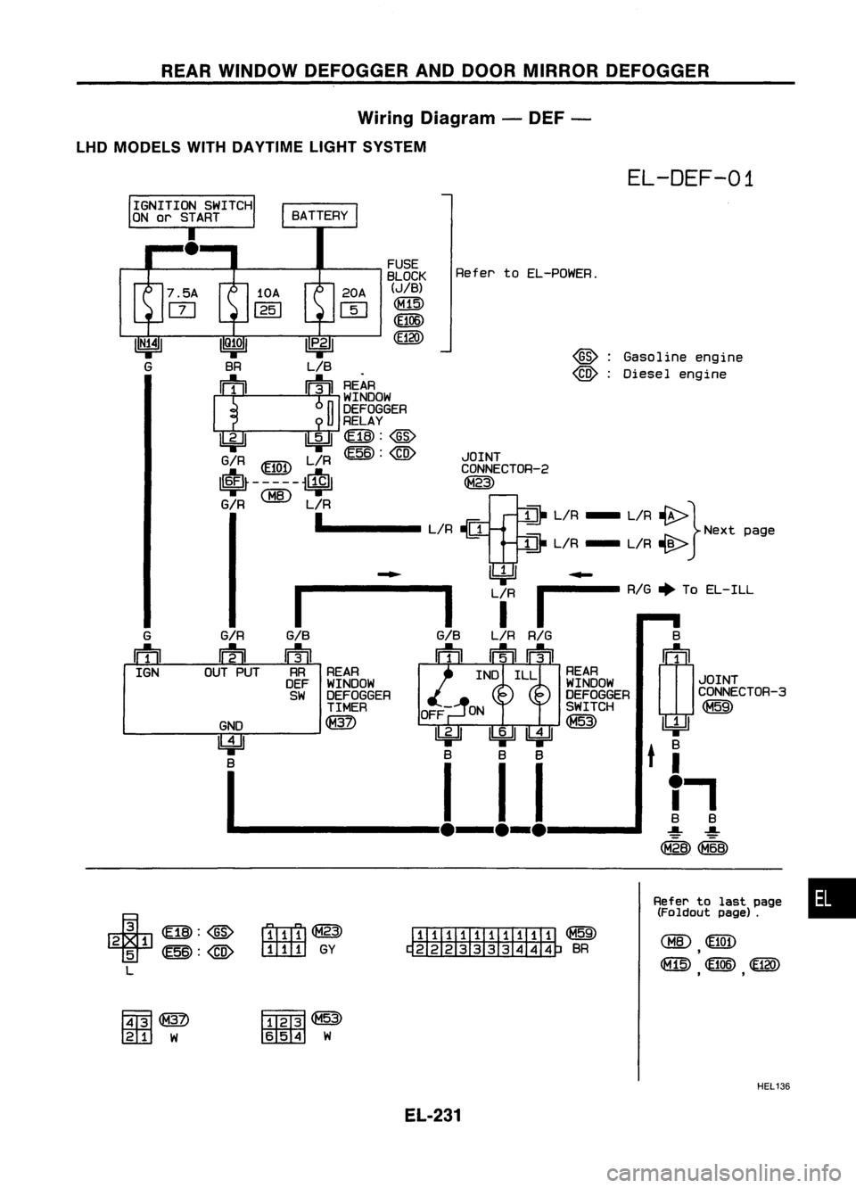
REARWINDOW DEFOGGER ANDDOOR MIRROR DEFOGGER
Wiring Diagram -DEF -
LHD MODELS WITHDAYTIME LIGHTSYSTEM
EL-DEF-01
Gasoline engine
Diesel engine
@:
@) :
Refer
toEL-POWER.
FUSE
BLOCK
(JIB)
CM15)
~06)
CE120)
20A
W
II
P•2
1
LIB
! ~
~¥~~OW
I
J
12~r~~GER
~ 1!:iJI~:@
G/R L/R~:
@
JOINT
~ ~ ~ CONNECTOR-2
I~~-----~ ~
G/R
1. L/R-[J
Et
L/R - L/R~} Nextpage
!di
L/R - L/R~
~ ~~
1-------
Lf
I
RIG
+
ToEL-ILL
G/B
L/R
RIG
B
n1il ~
n=tD (!J1
~f} ~¥~~OW INDILL ~¥~~OW JOINT
SW DEFOGGER DEFOGGERCONNECTOR-3
TIMER OFF SWITCH~
GND ~ ~
11111
11211 9F
~ ~t
B.
B BBB
I--ll-l-l 11
(M"2B)
G/R
~
OUT PUT
G
IftlJ
IGN
+
~:@
2 1
5
~:@
L
r1ITr1l~
ITITITJ
GY
ITIIIII:illTIIi
~
~BR
Refer
tolast page •
(Foldout page).
F.ffi1
tm::l
W
fffffi~
rn:mrn
W
HEL136
EL-231
Page 722 of 1701
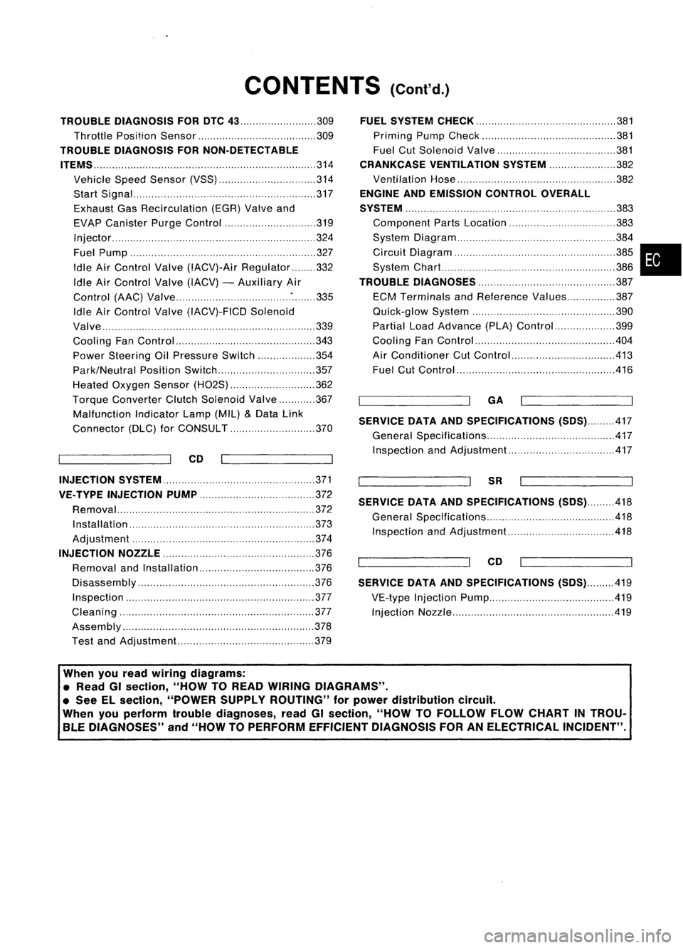
CONTENTS(Cont'd.)
TROUBLE DIAGNOSIS FORDTC
43 309
Throttle Position Sensor 309
TROUBLE DIAGNOSIS FORNON-DETECTABLE
ITEMS
314
Vehicle SpeedSensor (VSS) 314
Start Signal 317
Exhaust GasRecirculation (EGR)Valveand
EVAP Canister PurgeControl 319
Injector 324
Fuel Pump 327
Idle AirControl Valve(IACV)-Air Regulator 332
Idle AirControl Valve(IACV) -Auxiliary Air
Control (AAC)Valve :335
Idle AirControl Valve(IACV)-FICD Solenoid
Valve '"339
Cooling FanControl 343
Power Steering OilPressure Switch 354
Park/Neutral PositionSwitch 357
Heated Oxygen Sensor(H02S) 362
Torque
Converter
ClutchSolenoid Valve 367
Malfunction IndicatorLamp(MIL)
&
Data Link
Connector (DLC)forCONSULT 370
CD
INJECTION SYSTEM
371
VE.TYPE INJECTION PUMP
372
Removal 372
Installation 373
Adjustment 374
INJECTION NOZZLE
376
Removal andInstallation 376
Disassembly 376
Inspection 377
Cleaning 377
Assembly 378
Test andAdjustment 379
FUEL
SYSTEM CHECK
381
Priming PumpCheck 381
Fuel CutSolenoid Valve 381
CRANKCASE VENTILATION SYSTEM
382
Ventilation Hose 382
ENGINE ANDEMISSION CONTROLOVERALL
SYSTEM
383
Component PartsLocation 383
System Diagram 384
Circuit Diagram ,385
System Chart. 386
TROUBLE DIAGNOSES
387
ECM Terminals andReference Values 387
Quick-glow System 390
Partial LoadAdvance (PLA)Control 399
Cooling FanControl 404
Air Conditioner CutControl 413
Fuel CutControl 416
GA
SERVICE DATAANDSPECIFICATIONS
(505).417
General Specifications 417
Inspection andAdjustment.. 417
SR
SERVICE DATAANDSPECIFICATIONS
(505).418
General Specifications 418
Inspection andAdjustment.. .418
CD
SERVICE DATAANDSPECIFICATIONS
(505).419
VE-type Injection Pump 419
Injection Nozzle 419
•
When youread wiring diagrams:
• Read GIsection, "HOWTOREAD WIRING DIAGRAMS" .
• See Elsection, "POWER SUPPLYROUTING" forpower distribution circuit.
When youperform troublediagnoses, readGIsection, "HOWTOFOllOW FLOWCHART INTROU-
BLE DIAGNOSES" and"HOW TOPERFORM EFFICIENT DIAGNOSIS FORANELECTRICAL INCIDENT".
Page 779 of 1701
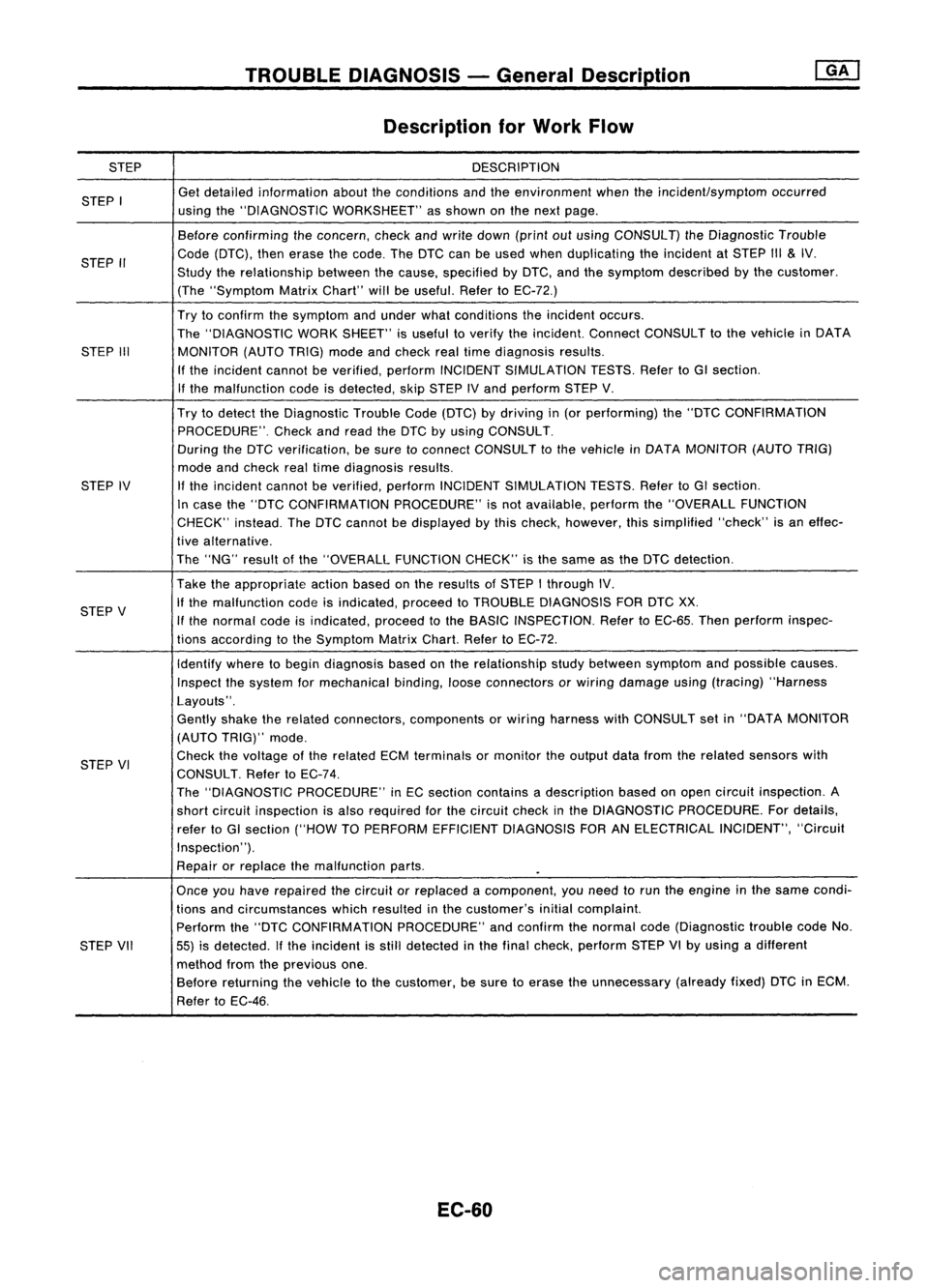
STEP
STEP I
STEP II
STEP III
STEP IV
STEP V
STEP VI
STEP VII
TROUBLE
DIAGNOSIS -General oescrip_ti_on
I_G_A_'
Description forWork Flow
DESCRIPTION
Get detailed information abouttheconditions andtheenvironment whentheincident/symptom occurred
using the"DIAGNOSTIC WORKSHEET" asshown onthe next page.
Before confirming theconcern, checkandwrite down (printoutusing CONSULT) theDiagnostic Trouble
Code (DTC), thenerase thecode. TheDTC canbeused when duplicating theincident atSTEP III
&
IV.
Study therelationship betweenthecause, specified byDTC, andthesymptom described bythe customer.
(The "Symptom MatrixChart" willbeuseful. RefertoEC-72.)
Try toconfirm thesymptom andunder whatconditions theincident occurs.
The "DIAGNOSTIC WORKSHEET" isuseful toverify theincident. ConnectCONSULT tothe vehicle inDATA
MONITOR (AUTOTRIG)modeandcheck realtime diagnosis results.
If the incident cannotbeverified, performINCIDENT SIMULATION TESTS.RefertoGI section.
If the malfunction codeisdetected, skipSTEP IVand perform STEPV.
Try todetect theDiagnostic TroubleCode(DTC) bydriving in(or performing) the"DTC CONFIRMATION
PROCEDURE". Checkandread theDTC byusing CONSULT.
During theDTC verification, besure toconnect CONSULT tothe vehicle inDATA MONITOR (AUTOTRIG)
mode andcheck realtime diagnosis results.
If
the incident cannotbeverified, performINCIDENT SIMULATION TESTS.RefertoGI section.
In case the"DTC CONFIRMATION PROCEDURE"isnot available, performthe"OVERALL FUNCTION
CHECK" instead.TheDTC cannot bedisplayed bythis check, however, thissimplified "check"isan effec-
tive alternative.
The "NG" result ofthe "OVERALL FUNCTIONCHECK"isthe same asthe DTC detection.
Take theappropriate actionbasedonthe results ofSTEP Ithrough IV.
If the malfunction codeisindicated, proceedtoTROUBLE DIAGNOSIS FORDTCXX.
If the normal codeisindicated, proceedtothe BASIC INSPECTION. RefertoEC-65. Thenperform inspec-
tions according tothe Symptom MatrixChart.RefertoEC-72.
Identify wheretobegin diagnosis basedonthe relationship studybetween symptom andpossible causes.
Inspect thesystem formechanical binding,looseconnectors orwiring damage using(tracing) "Harness
Layouts".
Gently shaketherelated connectors, components orwiring harness withCONSULT setin"DATA MONITOR
(AUTO TRIG)" mode.
Check thevoltage ofthe related ECMterminals ormonitor theoutput datafrom therelated sensors with
CONSULT. RefertoEC-74.
The "DIAGNOSTIC PROCEDURE" inEC section contains adescription basedonopen circuit inspection. A
short circuit inspection isalso required forthe circuit checkinthe DIAGNOSTIC PROCEDURE. Fordetails,
refer toGI section ("HOWTOPERFORM EFFICIENT DIAGNOSIS FORANELECTRICAL INCIDENT","Circuit
Inspection' ').
Repair orreplace themalfunction parts.
Once youhave repaired thecircuit orreplaced acomponent, youneed torun theengine inthe same condi-
tions andcircumstances whichresulted inthe customer's initialcomplaint.
Perform the"DTC CONFIRMATION PROCEDURE"andconfirm thenormal code(Diagnostic troublecodeNo.
55) isdetected. Ifthe incident isstill detected inthe final check, perform STEPVIby using adifferent
method fromtheprevious one.
Before returning thevehicle tothe customer, besure toerase theunnecessary (alreadyfixed)DTCinECM.
Refer toEC-46.
EC-60
Page 784 of 1701

TROUBLEDIAGNOSIS -General Description
Goto
(J.
Adjust ignition timingby
turning distributor.
No
NG
(Go to
@
onnext page.)
OK
CONNECT
CONSULTTOTHE VEHICLE.
Connect "CONSULT" tothe data link
connector forCONSULT andselect
"ENGINE" fromthemenu. Referto
EC-36
DOES ENGINE START?
BEFORE
STARTING
1. Check service records forany recent
repairs thatmay indicate arelated •
problem, orthe current needfor
scheduled maintenance.
2. 9pen engine hoodandcheck thefol.
lowing:
• Harness connectors forimproper con-
nections
• Vacuum hosesforsplits, kinks,or
improper connections
• Wiring forimproper connections,
pinches, orcuts
CHECK IGNITION TIMING.
1. Warm upengine sufficiently.
2. Stop engine anddisconnect throttle
position sensorharness connector.
3. Start engine.
4. Check ignition timingatidle using
timing light.
Ignition liming:
Refer toEC-36.
Basic
Inspection
Precaution:
Perform BasicInspection withoutelectrical or
mechanical loads
applied;
• Headlamp switchisOFF,
• Air conditioner switchisOFF,
• Rear defogger switchisOFF,
• Steering wheelisin the straight-ahead position,etc.
m
\\
~
~ SEF1421
~use box
~-~
vll-JI-
Datalinkconnector~'
EC-65