engine wiring NISSAN ALMERA N15 1995 Owner's Guide
[x] Cancel search | Manufacturer: NISSAN, Model Year: 1995, Model line: ALMERA N15, Model: NISSAN ALMERA N15 1995Pages: 1701, PDF Size: 82.27 MB
Page 985 of 1701
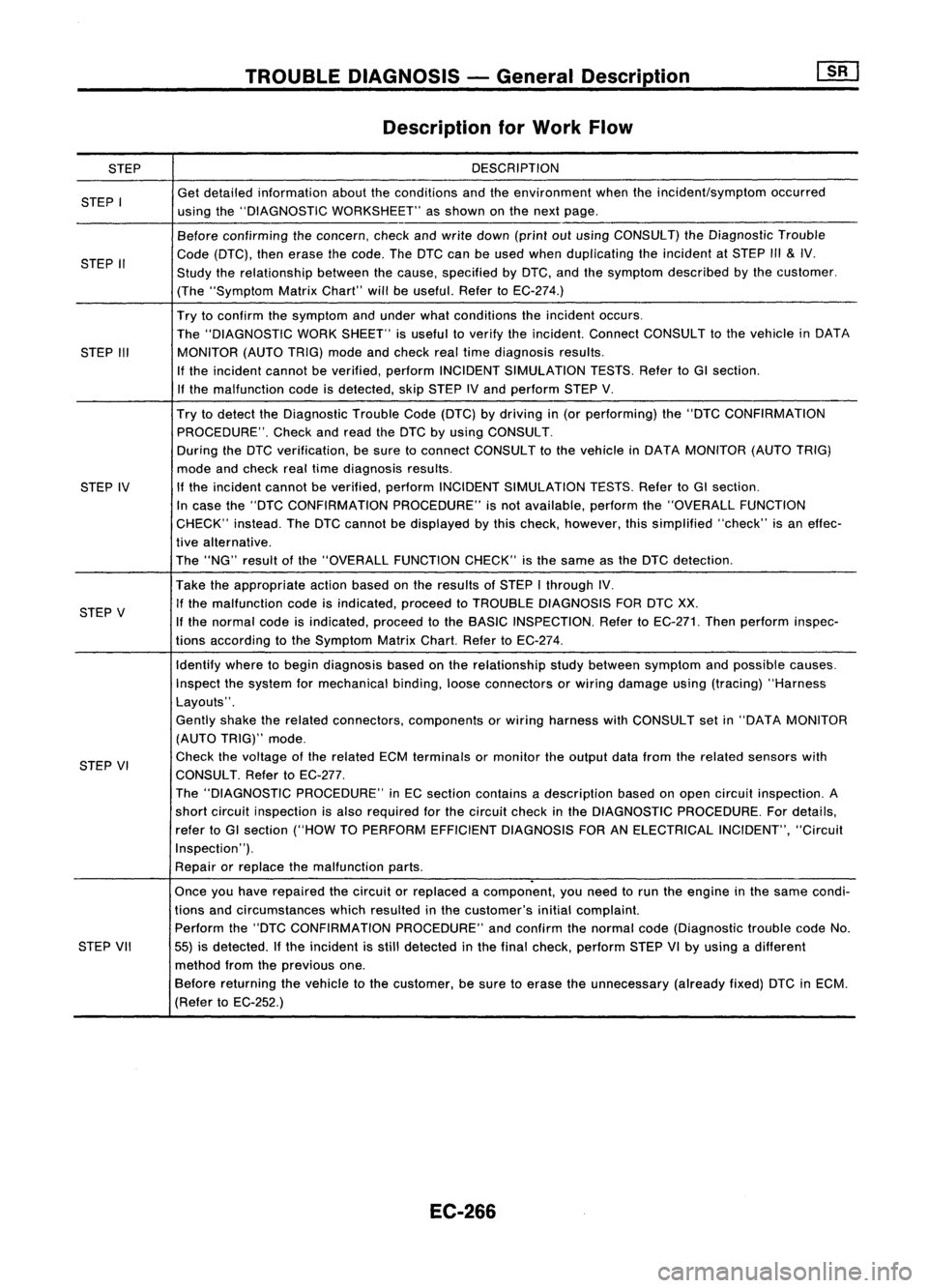
STEP
STEP I
STEP II
STEP III
STEP IV
STEP V
STEP VI
STEP VII
TROUBLE
DIAGNOSIS -General Description
Description forWork Flow
DESCRIPTION
Get detailed information abouttheconditions andtheenvironment whentheincident/symptom occurred
using the"DIAGNOSTIC WORKSHEET" asshown onthe next page.
Before confirming theconcern, checkandwrite down (printoutusing CONSULT) theDiagnostic Trouble
Code (DTC), thenerase thecode. TheDTC canbeused when duplicating theincident atSTEP
1/1
&
IV.
Study therelationship betweenthecause, specified byDTC, andthesymptom described bythe customer.
(The "Symptom MatrixChart" willbeuseful. RefertoEC-274.)
Try toconfirm thesymptom andunder whatconditions theincident occurs.
The "DIAGNOSTIC WORKSHEET" isuseful toverify theincident. ConnectCONSULT tothe vehicle inDATA
MONITOR (AUTOTRIG)modeandcheck realtime diagnosis results.
If the incident cannotbeverified, performINCIDENT SIMULATION TESTS.RefertoGI section.
If the malfunction codeisdetected, skipSTEP IVand perform STEPV.
Try todetect theDiagnostic TroubleCode(DTC) bydriving in(or performing) the"DTC CONFIRMATION
PROCEDURE". Checkandread theDTC byusing CONSULT.
During theDTC verification, besure toconnect CONSULT tothe vehicle inDATA MONITOR (AUTOTRIG)
mode andcheck realtime diagnosis results.
If the incident cannotbeverified, performINCIDENT SIMULATION TESTS.RefertoGI section.
In case the"DTC CONFIRMATION PROCEDURE"isnot available, performthe"OVERALL FUNCTION
CHECK" instead.TheDTC cannot bedisplayed bythis check, however, thissimplified "check"isan effec-
tive alternative.
The "NG" result ofthe "OVERALL FUNCTIONCHECK"isthe same asthe DTC detection.
Take theappropriate actionbasedonthe results ofSTEP Ithrough IV.
If the malfunction codeisindicated, proceedtoTROUBLE DIAGNOSIS FORDTCXX.
If the normal codeisindicated, proceedtothe BASIC INSPECTION. RefertoEC-271. Thenperform inspec-
tions according tothe Symptom MatrixChart.RefertoEC-274.
Identify wheretobegin diagnosis basedonthe relationship studybetween symptom andpossible causes.
Inspect thesystem formechanical binding,looseconnectors orwiring damage using(tracing) "Harness
Layouts".
Gently shaketherelated connectors, components orwiring harness withCONSULT setin"DATA MONITOR
(AUTO TRIG)" mode.
Check thevoltage ofthe related ECMterminals ormonitor theoutput datafrom therelated sensors with
CONSULT. RefertoEC-277.
The "DIAGNOSTIC PROCEDURE" inEC section contains adescription basedonopen circuit inspection. A
short circuit inspection isalso required forthe circuit checkinthe DIAGNOSTIC PROCEDURE. Fordetails,
refer toGI section ("HOWTOPERFORM EFFICIENT DIAGNOSIS FORANELECTRICAL INCIDENT","Circuit
Inspection").
Repair orreplace themalfunction parts.
.
Once youhave repaired thecircuit orreplaced acomponent, youneed torun theengine inthe same condi-
tions andcircumstances whichresulted inthe customer's initialcomplaint.
Perform the"DTC CONFIRMATION PROCEDURE"andconfirm thenormal code(Diagnostic troublecodeNo.
55) isdetected. Ifthe incident isstill detected inthe final check, perform STEPVIby using adifferent
method fromtheprevious one.
Before returning thevehicle tothe customer, besure toerase theunnecessary (alreadyfixed)DTCinECM.
(Refer toEC-252.)
EC-266
Page 990 of 1701

TROUBLEDIAGNOSIS -General Descrip_ti_on
1S_R_'
Basic Inspection
Precaution:
Perform BasicInspection withoutelectrical ormechanical loads
applied;
• Headlamp switchisOFF,
• Air conditioner switchisOFF,
• Rear defogger switchisOFF,
• Steering wheelisinthe straight-ahead position,etc.
m
BEFORE STARTING
1. Check service records forany recent •
repairs thatmay indicate arelated
problem, orthe current needfor
scheduled maintenance.
2. Open engine hoodandcheck thefol-
lowing:
• Harness connectors forimproper con-
nections
• Vacuum hosesforsplits, kinks,or
improper connections
• Wiring forimproper connections,
pinches, orcuts
Goto
(I.
No
CONNECT
CONSULTTOTHE VEHICLE.
Connect "CONSULT" tothe data link
connector forCONSULT andselect
"ENGINE" fromthemenu. Referto
EC-254.
DOES ENGINE START?
\\
~
~ SEF1421
START
•
IGN TIMING ADJ.
0
IGNITION TIMINGFEEDBACK
CONTROL WILLBEHELD BY
TOUCHING START
AFTER DOING SO,ADJUST
IGNITION TIMINGWITHA
TIMING LIGHTBYTURNING
THE CAMSHAFT POSITION
SENSOR.
SEF555N
Yes
CHECK IGNITION TIMING.
(ij\
1.Warm upengine sufficiently.
~ 2.Select "IGNTIMING ADJ"in
"WORK SUPPORT" mode.
3. Touch "START".
4. Check ignition timingatidle
using timing light.
Ignition timing:
15°::f:2° BTDC
~ 1Warm upengine sufficiently.
~ 2:
Stop engine anddisconnect
throttle position sensorhar-
ness connector.
3. Start engine.
4. Check ignition timingatidle
using timing light.
Ignition timing:
15°::f:2° BTDC
OK
(Go to
@
onnext page.) Adjust
ignition timingby
turning distributor.
EC-271
Page 1320 of 1701
Drainplug(Radiator)
SFA110A
SFA 1538
SEM534D ENGINE
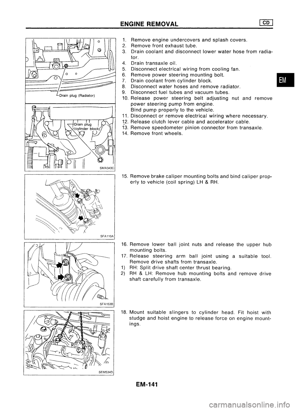
REMOVAL
1. Remove engineundercovers andsplash covers.
2. Remove frontexhaust tube.
3. Drain coolant anddisconnect lowerwater hosefromradia-
tor.
4. Drain transaxle oil.
5. Disconnect electricalwiringfromcooling fan.
6. Remove powersteering mounting bolt. •
7. Drain coolant fromcylinder block.
8. Disconnect waterhoses andremove radiator.
9. Disconnect fueltubes andvacuum tubes.
10. Release powersteering beltadjusting nutand remove
power steering pumpfromengine.
Bind pump properly tothe vehicle.
11. Disconnect orremove electrical wiringwhere necessary.
12. Release clutchlevercable andaccelerator cable.
13. Remove speedometer pinionconnector fromtransaxle.
14. Remove frontwheels.
15. Remove brakecaliper mounting boltsandbind caliper prop-
erly tovehicle (coilspring) LH
&
RH.
16. Remove lowerballjoint nutsandrelease theupper hub
mounting bolts.
17. Release steering armballjoint using asuitable tool.
Remove driveshafts fromtransaxle.
1) RH: Split drive shaftcenter thrustbearing.
2) RH
&
LH: Remove hubmounting boltsandremove drive
shaft carefully fromtransaxle.
18. Mount suitable slingers tocylinder head.Fithoist with
studge andhoist engine torelease forceonengine mount-
ings.
EM-141
Page 1355 of 1701
GENERALINFORMATION •
SECTION
G
I
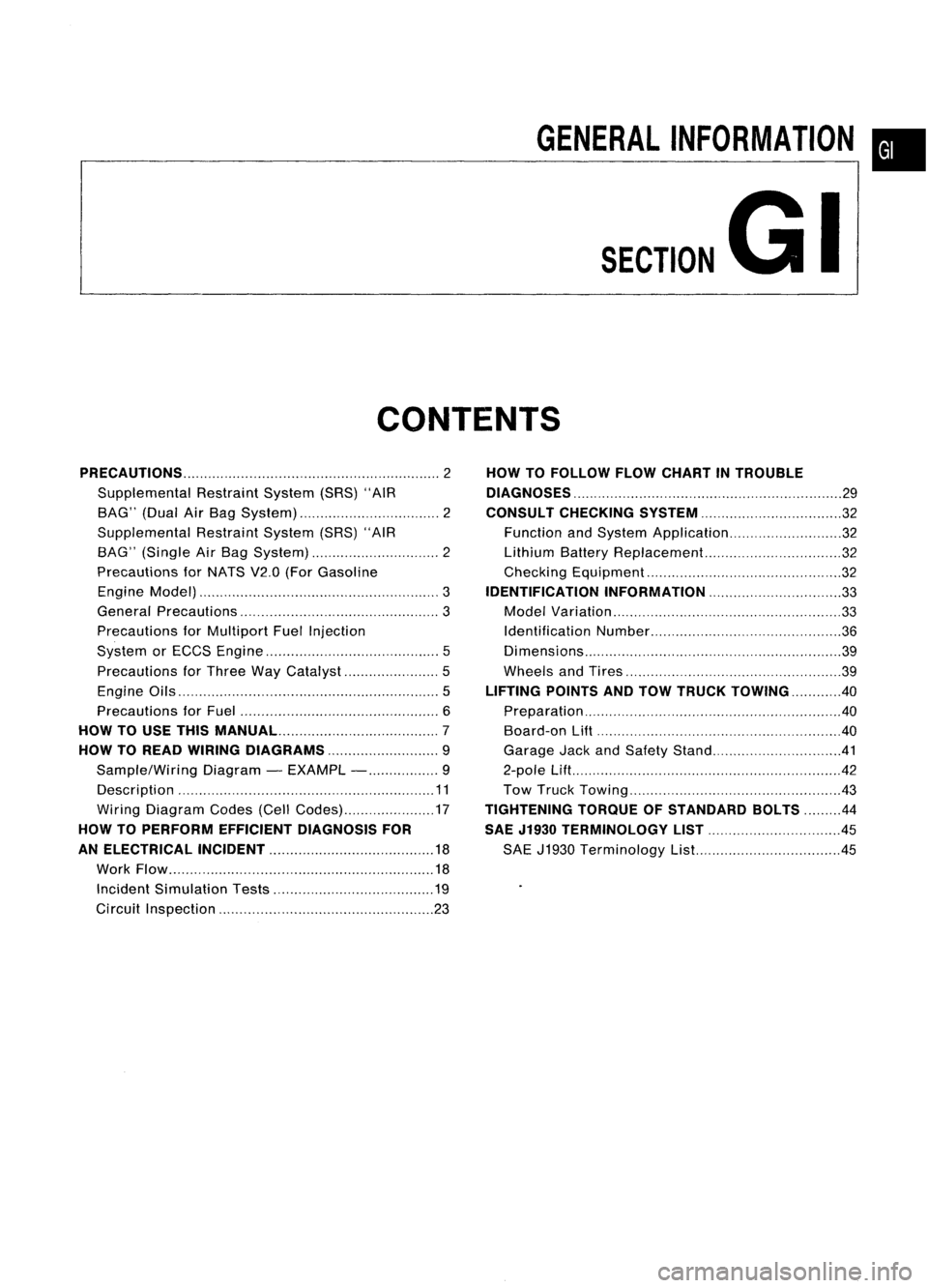
CONTENTS
PRECAUTIONS 2
Supplemental RestraintSystem(SRS)"AIR
BAG" (DualAirBag System) 2
Supplemental RestraintSystem(SRS)"AIR
BAG" (Single AirBag System) 2
Precautions forNATS V2.0(ForGasoline
Engine Model) 3
General Precautions 3
Precautions forMultiport FuelInjection
System orECCS Engine 5
Precautions forThree WayCatalyst 5
Engine Oils 5
Precautions forFuel 6
HOW TOUSE THIS
MANUAL 7
HOW TOREAD WIRING DIAGRAMS 9
Sample/Wiring Diagram-EXAMPL - 9
Description 11
Wiring Diagram Codes(CellCodes) 17
HOW TOPERFORM EFFICIENT DIAGNOSIS FOR
AN ELECTRICAL INCIDENT 18
Work Flow 18
Incident Simulation Tests 19
Circuit Inspection 23
HOW
TOFOLLOW FLOWCHART INTROUBLE
DIAGNOSES 29
CONSULT CHECKING SYSTEM
32
Function andSystem Application 32
Lithium BatteryReplacement.. 32
Checking Equipment 32
IDENTIFICATION INFORMATION 33
Model Variation 33
Identification Number 36
Di mens ions 39
Wheels andTires 39
LIFTING POINTSANDTOW TRUCK TOWING ..40
Preparation 40
Board-on
Lift
40
Garage JackandSafety Stand 41
2-pole Lift 42
Tow Truck Towing 43
TIGHTENING TORQUEOFSTANDARD BOLTS
44
SAE J1930 TERMINOLOGY LIST 45
SAE J1930 Terminology List.. 45
Page 1370 of 1701
HOWTOREAD WIRING DIAGRAMS
Description (Cont'd)
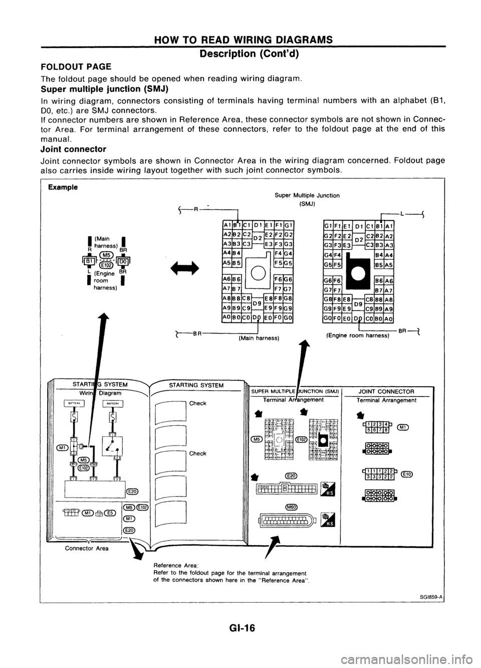
FOLDOUT PAGE
The foldout pageshould beopened whenreading wiringdiagram.
Super multiple junction (SMJ)
In wiring diagram, connectors consistingofterminals havingterminal numbers withanalphabet (81,
DO, etc.) areSMJ connectors.
If connector numbersareshown inReference Area,these connector symbolsarenotshown inConnec-
tor Area. Forterminal arrangement ofthese connectors, refertothe foldout pageatthe end ofthis
manual.
Joint connector
Joint connector symbolsareshown inConnector Areainthe wiring diagram concerned. Foldoutpage
also carries
insidewiring
layouttogether withsuch jointconnector symbols.
Example SuperMultiple Junction
(SMJ)
L----S
I
(Main
I
R harness)
@
BR
1~~_~_5 __
1~1
....... @ID .......
L (Engine BR
I
room
I
harness) AlB1Cl
01ElFIGl
A2B2 C202 E2F2G2
A3B3C3 E3F3G3
A4B4
@]
F4G4
5 B5 F55
A6B6
0
F6G6
A7B7 F77
A8B8C8 E8F8G8
09
A989C9 E9F9G9
AO BOCO DO EOFOGO Gl
FlEl 01ClBlAl
2F2E202C2B2A2
G3 F3E3 C3B3 A3
G4F4
C
B4A4
G5 F5 B5A5
G6 F6 86A6
G7F7 B7A7
G8F8 E8 C888A8
09
G9 F9E9 C989A9
GO FOEO 0 COBO AO
r-
BR
(Mainharness) (Engine
roomharness) BR----{
rDI.TI:IImP
[ill![ill]
@g)
JOINT
CONNECTOR
Terminal Arrangement
*
r::t::rrm::m:J
'M'i'
[ill]II!J ~
*
~
rll"
!! !
I
!
I II
!I
I
'J ~
~lllll!I!!lIllbV ~
SUPER
MULTIPLE UNCTION(SMJ)
Terminal Arangement
*
@)
~=fH+H=1
[II
STARTING
SYSTEM
G
SYSTEM
Diagram
~r-
[Jcheck
CJ
OCh~'
o
[J
STARTI
Wirin
@(3)
'tffB'
@)
Qfu@
@)
@
"-)-~
y
Connector Area
ReferenceArea:
Refer tothe foldout pageforthe terminal arrangement
of the connectors shownhereinthe "Reference Area".
SG1859-A
GI-16
Page 1371 of 1701
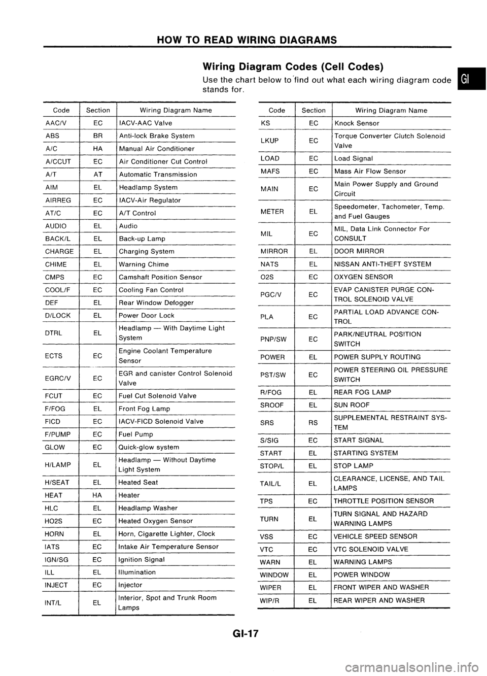
HOWTOREAD WIRING DIAGRAMS
Wiring Diagram Codes(CellCodes)
Use thechart below to'find outwhat each wiring diagram code•
stands for,
Code Section WiringDiagram Name
AACIV ECIACV-AAC
Valve
ABS BR
Anti-lock BrakeSystem
A/C HAManualAirConditioner
A/CCUT ECAir
Conditioner CutControl
A/T ATAutomatic Transmission
AIM ELHeadlamp System
AIRREG ECIACV-Air Regulator
AT/C ECA/TControl
AUDIO ELAudio
BACK/L ELBack-up Lamp
CHARGE ELCharging System
CHIME ELWarning Chime
CMPS EC
Camshaft PositionSensor
COOllF ECCooling
FanControl
DEF ELRearWindow Defogger
D/LOCK ELPowerDoorLock
DTRL ELHeadlamp
-With Daytime Light
System
ECTS ECEngine
Coolant Temperature
Sensor
EGR andcanister ControlSolenoid
EGRCIV EC
Valve
FCUT ECFuel
CutSolenoid Valve
F/FOG ELFront
FogLamp
FICO ECIACV-FICD
SolenoidValve
F/PUMP ECFuel
Pump
GLOW ECQuick-glow
system
H/LAMP ELHeadlamp
-Without Daytime
Light System
H/SEAT ELHeated
Seat
HEAT HA
Heater
HLC ELHeadlamp
Washer
H02S ECHeated
Oxygen Sensor
HORN ELHorn,
Cigarette Lighter,Clock
IATS ECIntake
AirTemperature Sensor
IGN/SG ECIgnition
Signal
ILL ELIllumination
INJECT ECInjector
INT/L ELInterior,
SpotandTrunk Room
Lamps Code
Section WiringDiagram Name
KS ECKnock
Sensor
LKUP ECTorque
Converter ClutchSolenoid
Valve
LOAD ECLoadSignal
MAFS ECMass
AirFlow Sensor
MAIN ECMain
Power Supply andGround
Circuit
METER ELSpeedometer,
Tachometer,Temp.
and Fuel Gauges
MIL ECMIL,
Data LinkConnector For
CONSULT
MIRROR ELDOOR
MIRROR
NATS ELNISSAN
ANTI-THEFT SYSTEM
02S ECOXYGEN
SENSOR
EC EVAP
CANISTER PURGECON-
PGCIV TROLSOLENOID VALVE
PLA ECPARTIAL
LOADADVANCE CON-
TROL
EC PARK/NEUTRAL
POSITION
PNP/SW SWITCH
POWER ELPOWER
SUPPLY ROUTING
POWER STEERING OILPRESSURE
PST/SW EC
SWITCH
R/FOG ELREAR
FOGLAMP
SROOF ELSUN
ROOF
SUPPLEMENTAL RESTRAINTSYS-
SRS RS
TEM
S/SIG ECST
ART SIGNAL
START ELSTARTING
SYSTEM
STOP/L ELSTOP
LAMP
TAllIL ELCLEARANCE,
LICENSE,ANDTAIL
LAMPS
TPS ECTHROTTLE
POSITIONSENSOR
TURN SIGNAL ANDHAZARD
TURN EL
WARNING LAMPS
VSS ECVEHICLE
SPEEDSENSOR
VTC ECVTC
SOLENOID VALVE
WARN ELWARNING
LAMPS
WINDOW ELPOWER
WINDOW
WIPER ELFRONT
WIPERANDWASHER
WIP/R ELREAR
WIPER ANDWASHER
GI-17
Page 1372 of 1701
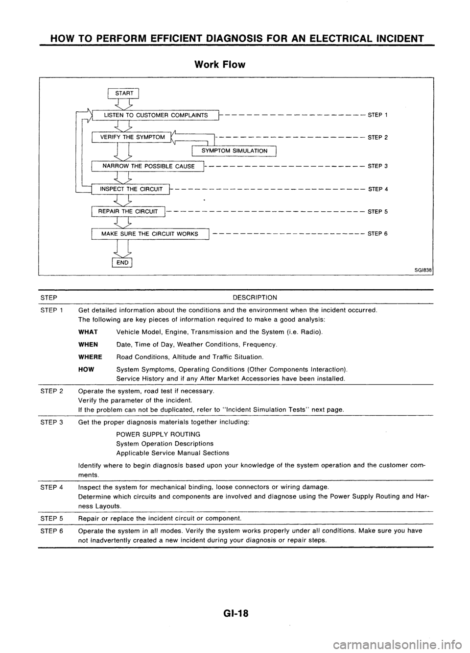
HOWTOPERFORM EFFICIENT DIAGNOSIS FORANELECTRICAL INCIDENT
Work Flow
- - - -- - -- ------ -- - -- STEP 1
--------------------- STEP2
----------------------- STEP3
- - -- ---- - --- - -- --- --- - - --- -- STEP 4
--------- -------------------- STEP5
- - - - ---- -- -- -- -- -- --- --- STEP 6
SGI838
STEP
STEP 1 DESCRIPTION
Get detailed information abouttheconditions andtheenvironment whentheincident occurred.
The following arekey pieces ofinformation requiredtomake agood analysis:
HOW
WHEN
WHAT
WHERE
Vehicle
Model,Engine, Transmission andtheSystem (i.e.Radio).
Date, TimeofDay, Weather Conditions, Frequency.
Road Conditions, AltitudeandTraffic Situation.
System Symptoms, OperatingConditions (OtherComponents Interaction).
Service Historyandifany After Market Accessories havebeen installed.
Operate thesystem, roadtestifnecessary.
Verify theparameter ofthe incident.
If the problem cannotbeduplicated, referto"Incident Simulation Tests"nextpage.
STEP
2
STEP 3Get
theproper diagnosis materialstogetherincluding:
POWER SUPPLY ROUTING
System Operation Descriptions
Applicable ServiceManualSections
Identify wheretobegin diagnosis baseduponyourknowledge ofthe system operation andthecustomer com-
ments.
STEP 4
STEP 5
STEP 6 Inspect
thesystem formechanical binding,looseconnectors orwiring damage.
Determine whichcircuits andcomponents areinvolved anddiagnose usingthePower Supply Routing andHar-
ness Layouts.
Repair orreplace theincident circuitorcomponent.
Operate thesystem inall modes. Verifythesystem worksproperly underallconditions. Makesureyouhave
not inadvertently createdanew incident duringyourdiagnosis orrepair steps.
GI-18
Page 1373 of 1701
HOWTOPERFORM EFFICIENT DIAGNOSIS FORANELECTRICAL INCIDENT
Incident Simulation Tests
INTRODUCTION
Sometimes thesymptom isnot present whenthevehicle isbrought infor service.
If
possible, re-create
the conditions presentatthe time ofthe incident. Doingsomay help avoid aNo Trouble FoundDiag-
nosis. Thefollowing sectionillustrates waystosimulate theconditionslenvironment underwhich the
owner experiences anelectrical incident.
The section isbroken intothesixfollowing topics:
• Vehicle vibration
• Heat sensitive
• Freezing
• Water intrusion
• Electrical load
• Cold orhot start up
Get athorough description ofthe incident fromthecustomer. Itis important forsimulating thecondi-
tions ofthe problem.
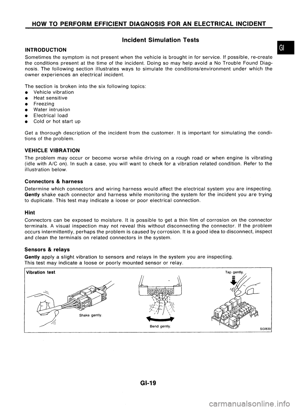
VEHICLE VIBRATION
The problem mayoccur orbecome worsewhiledriving onarough roadorwhen engine isvibrating
(idle with
AIC
on). Insuch acase, youwillwant tocheck foravibration relatedcondition. Refertothe
illustration below.
Connectors
&
harness
Determine whichconnectors andwiring harness wouldaffecttheelectrical systemyouareinspecting.
Gently
shakeeachconnector andharness whilemonitoring thesystem forthe incident youaretrying
to duplicate. Thistestmay indicate aloose orpoor electrical connection.
Hint
Connectors canbeexposed tomoisture. Itis possible toget athin film ofcorrosion onthe connector
terminals. Avisual inspection maynotreveal thiswithout disconnecting theconnector. Ifthe problem
occurs intermittently, perhapstheproblem iscaused bycorrosion. Itis agood ideatodisconnect, inspect
and clean theterminals onrelated connectors inthe system.
Sensors
&
relays
Gently
applyaslight vibration tosensors andrelays inthe system youareinspecting.
This testmay indicate aloose orpoorly mounted sensororrelay.
•
Vibration test
Bendgently.
GI-19
Tap
gently.
8GI839
Page 1375 of 1701
HOWTOPERFORM EFFICIENT DIAGNOSIS FORANELECTRICAL INCIDENT
Incident Simulation Tests(Cont'd)
Engine compartment
There areseveral reasons avehicle orengine vibration could•
cause anelectrical complaint. Someofthe things tocheck for
are:
• Connectors notfully seated.
• Wiring harness notlong enough andisbeing stressed due
to engine vibrations orrocking.
• Wires laying across brackets ormoving components.
• Loose, dirtyorcorroded groundwires.
• Wires routed tooclose tohot components.
To inspect components underthehood, startbyverifying the
integrity ofground connections. (RefertoGROUND INSPEC-
TION described later.)Firstcheck thatthesystem isproperly
grounded. Thencheck forloose connection by
gently shaking
the wiring orcomponents aspreviously explained. Usingthe
wiring diagrams inspectthewiring forcontinuity.
Behind theinstrument panel
An improperly routedorimproperly clampedharnesscan
become pinchedduringaccessory installation. Vehiclevibra-
tion canaggravate aharness whichisrouted alongabracket
or near ascrew.
Under seating areas
An unclamped orloose harness cancause wiring tobe pinched
by seat components (suchasslide guides) duringvehicle vibra-
tion. Ifthe wiring runsunder seating areas,inspect wirerout-
ing forpossible damageorpinching.
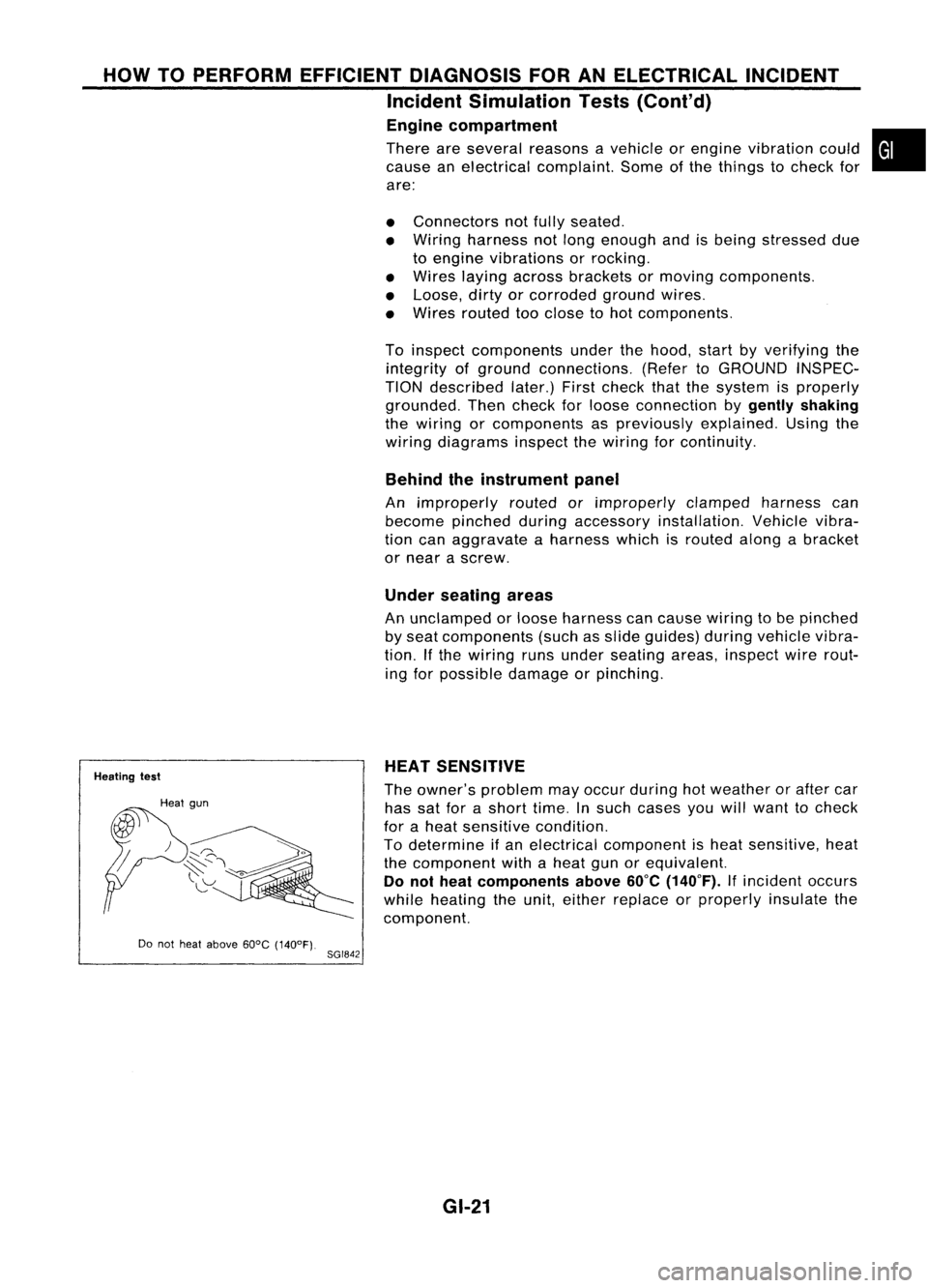
Heating test
Do not heat above 60°C(140°F).
8GI842 HEAT
SENSITIVE
The owner's problem mayoccur during hotweather orafter car
has satforashort time.Insuch cases youwillwant tocheck
for aheat sensitive condition.
To determine ifan electrical component isheat sensitive, heat
the component withaheat gunorequivalent.
Do not heat components above
60°C
(140°F).
Ifincident occurs
while heating theunit, either replace orproperly insulatethe
component.
GI-21
Page 1416 of 1701
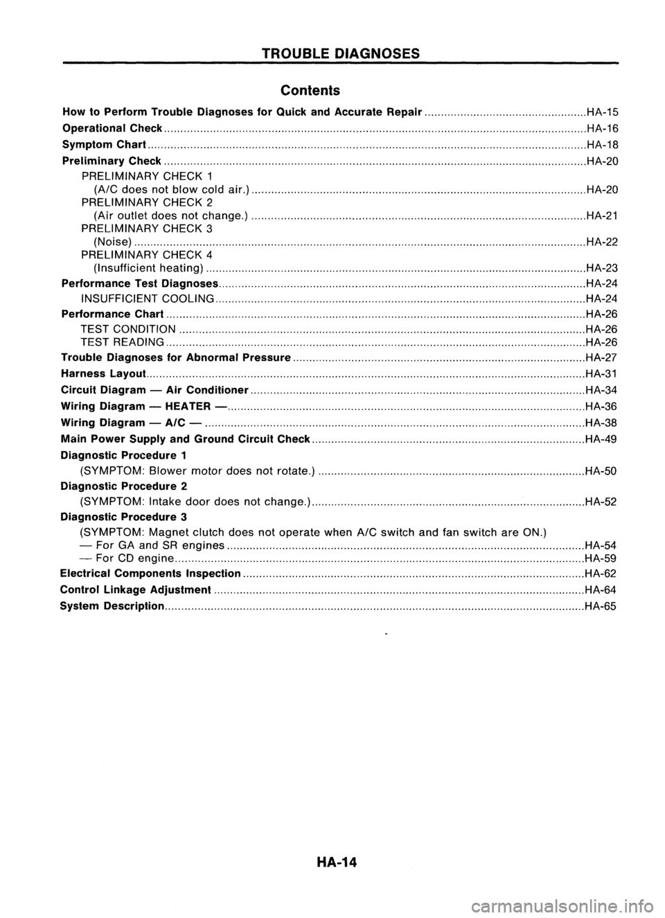
TROUBLEDIAGNOSES
Contents
How toPerform TroubleDiagnoses forQuick andAccurate Repair HA-15
Operational Check HA-16
Symptom Chart HA-18
Preliminary Check HA-20
PRELIMINARY CHECK1
(A/C
does notblow coldair.) HA-20
PRELIMINARY CHECK2
(Air outlet doesnotchange.) HA-21
PRELIMINARY CHECK3
(Noise) HA-22
PRELIMINARY CHECK4
(I nsufficient heating) HA-23
Performance TestDiagnoses HA-24
INSUFFICIENT COOLING HA-24
Performance Chart HA-26
TEST CONDITION HA-26
TEST READING HA-26
Trouble Diagnoses forAbnormal Pressure HA-27
Harness Layout. HA-31
Circuit Diagram -Air Conditioner HA-34
Wiring Diagram -HEATER - HA-36
Wiring Diagram -AIC - HA-38
Main Power Supply andGround CircuitCheck HA-49
Diagnostic Procedure1
(SYMPTOM: Blowermotordoesnotrotate.) HA-50
Diagnostic Procedure2
(SYMPTOM: Intake doordoes notchange.) HA-52
Diagnostic Procedure3
(SYMPTOM: Magnetclutchdoesnotoperate when
A/C
switch andfanswitch areON.)
- For GAand SRengines HA-54
- For CDengine HA-59
Electrical Components Inspection HA-62
Control Linkage Adjustment HA-64
System Description HA-65
HA-14