fuse box NISSAN ALMERA N15 1995 Owner's Guide
[x] Cancel search | Manufacturer: NISSAN, Model Year: 1995, Model line: ALMERA N15, Model: NISSAN ALMERA N15 1995Pages: 1701, PDF Size: 82.27 MB
Page 930 of 1701

TROUBLEDIAGNOSIS FORNON-DETECTABLE ITEMS
Electrical LoadSignal
•
EC-LOAD-01
ECM (ECCS
CONTROL
MODULE)
@:
Without daytime
light system
*1 ...
W
*2 ..'@RIL '@W/R
*3 ...
,
-: Detectable line
for DTC
-: Non-detectable
line forDTC
H/FAN
1~51
G/Y
I$ICEID
G/Y@
I
G/Y
rn~
I
JUNCTION
BOX
NO.2
(JOINT
CONNECTORS)
4=U~
G/Y
I
G/Y
~6
FAN
ON SWITCH
OFF--
@
l4dJ
B
Refer
to
EL-POWER.
2ND LIGHTING
SWITCH
(E107)
~
*2
I
O-
r.l. RILBIR
~ r=:b,r=:b,
111111 II1II
WIR
TAIL/LTAIL
~ DAYTIME
10A SWFUSELIGHT
1451
TAIL/L
UNIT
~
R/Y
L..-.,.,:..,OU;,.,...T....- --'
~
~ RIB
O--
I
*3
(I)
Q
1
3
I
(E106)
FUSE
BLOCK (JIB)
I~BI ~
RIG
1
RIG
.fA-.
Next
~page
75A
m
W BIR
~O-(QD-~
I
*1
rrffil
~T
OFF'-
LHD
MODELS
~
~GY
Refer
tolast page
(Foldout page).
~ CE106)
,
~
~@
~w
HEC054
EC-211
Page 960 of 1701
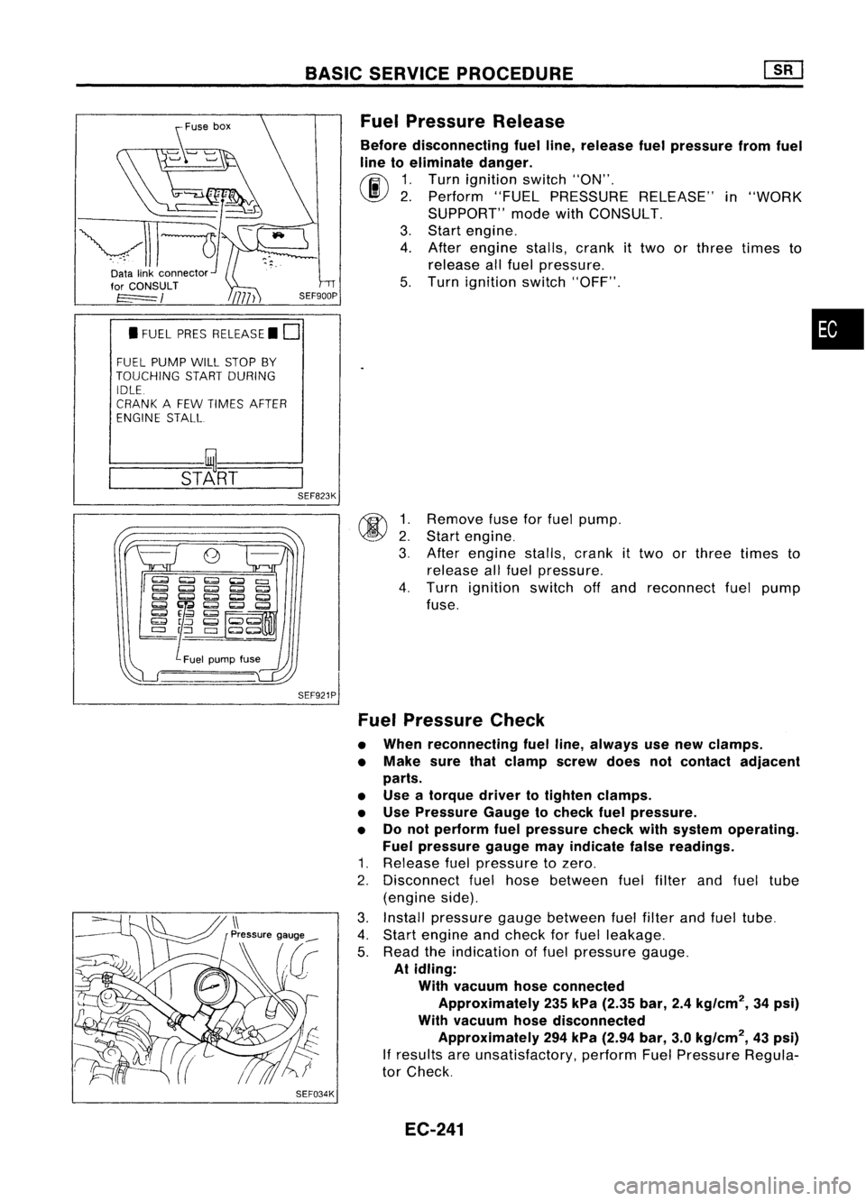
~U5e
box
~~~
~11~1-
Datalinkconnector ~"
for CONSULT
t=====/
• FUEL PRESRELEASE. D
FUEL PUMP WillSTOP BY
TOUCHING STARTDURING
IDLE.
CRANK AFEW TIMES AFTER
ENGINE STALL
---S-T~-RT--
BASIC
SERVICE PROCEDURE
Fuel Pressure Release
Before disconnecting fuelline, release fuelpressure fromfuel
line toeliminate danger.
~ 1.Turn ignition switch"ON".
\J!I}
2.Perform "FUELPRESSURE RELEASE"in"WORK
SUPPORT" modewithCONSULT.
3. Start engine.
4. After engine stalls,crankittwo orthree times to
release allfuel pressure.
5. Turn ignition switch"OFF".
•
@ ~:
3.
SEF823K
SEF921P
SEF034K
Remove
fuseforfuel pump.
Start engine.
After engine stalls,crank
it
two orthree times to
release allfuel pressure.
4. Turn ignition switchoffand reconnect fuelpump
fuse.
Fuel Pressure Check
• When reconnecting fuelline, always usenew clamps.
• Make surethatclamp screwdoesnotcontact adjacent
parts.
• Use atorque drivertotighten clamps.
• Use Pressure Gaugetocheck fuelpressure.
• Donot perform fuelpressure checkwithsystem operating.
Fuel pressure gaugemayindicate falsereadings.
1. Release fuelpressure tozero.
2. Disconnect fuelhose between fuelfilter andfuel tube
(engine side).
3. Install pressure gaugebetween fuelfilter andfuel tube.
4. Start engine andcheck forfuel leakage.
5. Read theindication offuel pressure gauge.
At idling:
With vacuum hoseconnected
Approximately 235kPa (2.35 bar,2.4kg/cm
2,
34psi)
With vacuum hosedisconnected
Approximately 294kPa (2.94 bar,3.0kg/cm
2,
43psi)
If
results areunsatisfactory, performFuelPressure Regula-
tor Check.
EC-241
Page 973 of 1701

ON-BOARDDIAGNOSTIC SYSTEMDESCRIPTION
for CONSULT
t======/
NISSANCONSULT EE940
+
I
~
I
START
I
SUB
MODE
I
SEF253Q CONSULT
CONSULT INSPECTION PROCEDURE
1. Turn offignition switch.
2. Connect "CONSULT" toData linkconnector forCONSULT.
(Data linkconnector forCONSULT islocated behindthefuse
box cover.)
3. Turn onignition switch.
4. Touch "START".
+:
Program card
AE930: ForAustralia
5. Touch "ENGINE",
~ SELECT~S=Y=S=TE=M====
ENGINE
SEF895K
~ SELECT DIAGMODE
[i]
WORK SUPPORT
SELF-DIAG RESULTS
DATA MONITOR
ACTIVE TEST
ECM PART NUMBER
FUNCTION TEST
SEF136P
6.
Perform eachdiagnostic testmode according toeach ser-
vice procedure.
For further information, seetheCONSULT Operation Manual.
EC-254
Page 1133 of 1701

TROUBLEDIAGNOSES
Air Conditioner CutControl (Cont'd)
LHD models
EC-A/CCUT-01
Refer toEL-POWEA.
OFF
LG/R~
I
,
I
I
ON
A/C
LG/R
I
SWITCH
m
I
OFF
@
I
THERMO
CONTROL
AMP.
~
ON
L/Y
~ ~
G/B G/BG/Y
THERMISTOR
I I
m
._-~--_. rn
JUNCTION
BOX
NO.2
To compressor (JOINT
._ L/R. (Referto CONNECTORS)
I
HA-A/C.)~~
G/Y
00
~E~N~~gD
I?iJ
~~~TCH
VALVE OFF--~
IkjJ
(E64) ~
B (E65) B
I
r1
I
• .., BBB
1 ~
1
i....l
mm ~~
RIL
~
t
FUSE
BLOCK
(JIB)
~
(BOO)
R/L
IriDl
A/C
DUAL-
PRESSURE SWITCH
~
1~11I~211~1
LIB LG/R LG/R
II-~ --
LIB
L/Y
IT ~IA/C
n
RELAY
U
UID
4=JJ~
L L/R
~L
rn
I
ECM(ENGINECONTROLMODULE)
---------- @
n
LOW HIGH
... ~~_.
NORMAL
I!4Jl
G
~~1;1$1
G
m
COMP
~(E16)
T
L
JS4.ffi
(tiS)
B
~-----------.,
I I
:ITl~ ~~:
I I
L
~
IQl@
~ W
Refer
tolast page
(Foldout page).
CMID
(El0n
,
lf1@
(E106)
,
~
HEC095
EC-414
Page 1365 of 1701
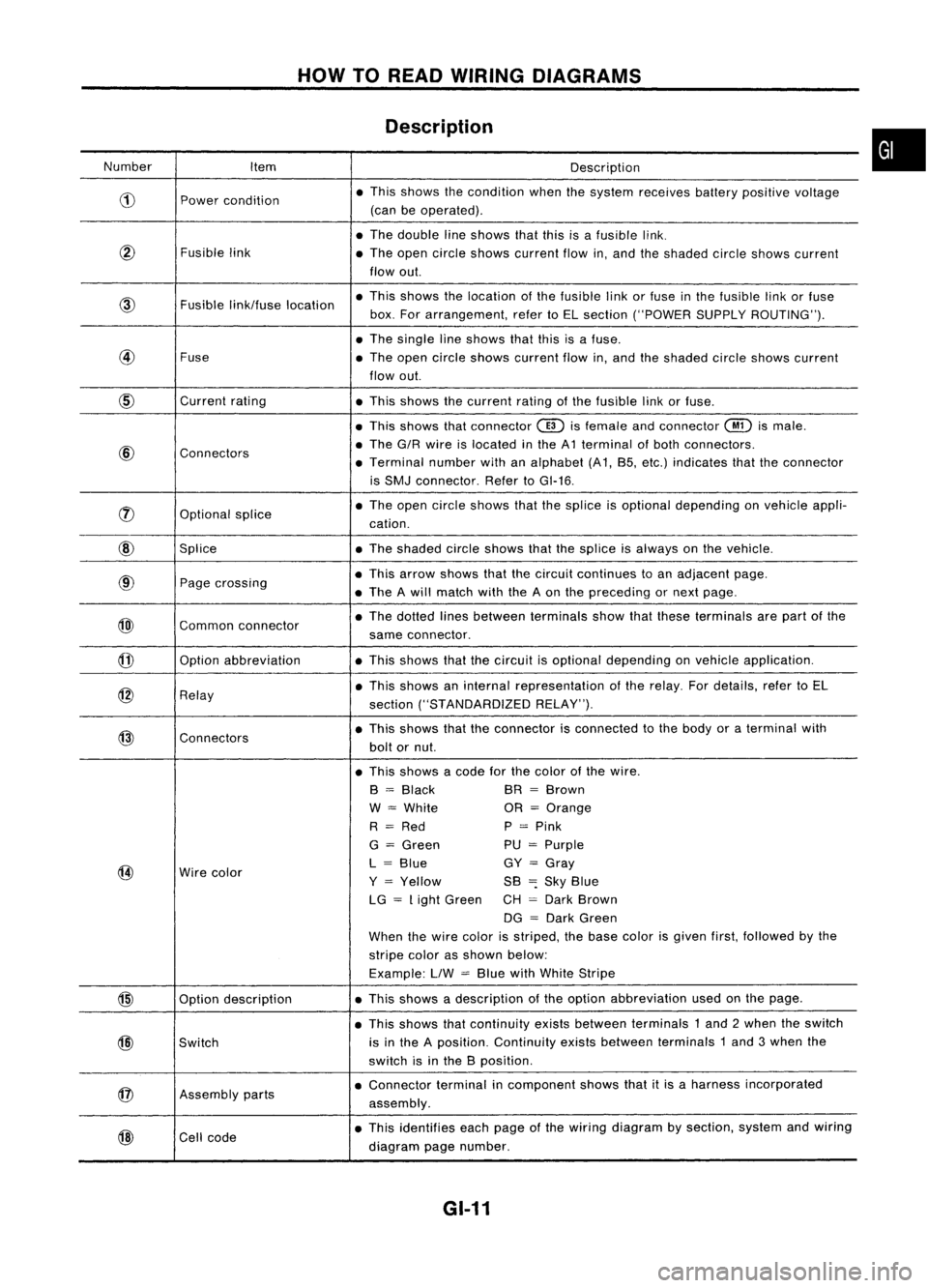
HOWTOREAD WIRING DIAGRAMS
Description
Number Item Description
CD
Power
condition •
This shows thecondition whenthesystem receives batterypositive voltage
(can beoperated) .
• The double lineshows thatthisisafusible link.
@
Fusiblelink
•The open circle shows current flowin,and theshaded circleshows current
flow out.
link/fuse location •
This shows thelocation ofthe fusible linkorfuse inthe fusible linkorfuse
box. Forarrangement, refertoEL section ("POWER SUPPLYROUTING") .
• The single lineshows thatthisisafuse.
@
Fuse
•The open circle shows current flowin,and theshaded circleshows current
flow out.
CID
Current
rating
•This shows thecurrent ratingofthe fusible linkorfuse .
• This shows thatconnector
@)
isfemale andconnector
@
ismale .
@
Connectors •
The G/R wire islocated inthe A1 terminal ofboth connectors.
• Terminal numberwithanalphabet (A1, B5, etc.) indicates thattheconnector
is SMJ connector. RefertoGI-16 .
rJ)
Optionalsplice •
The open circle shows thatthesplice isoptional depending onvehicle appli-
cation.
@
Splice •The shaded circleshows thatthesplice isalways onthe vehicle.
@
Page
crossing •
This arrow shows thatthecircuit continues toan adjacent page.
• The Awill match withtheAon the preceding ornext page .
@)
Commonconnector •
The dotted linesbetween terminals showthatthese terminals arepart ofthe
same connector.
@
Option
abbreviation •This shows thatthecircuit isoptional depending onvehicle application.
@
Relay •
This shows aninternal representation ofthe relay. Fordetails, refertoEL
section ("STANDARDIZED RELAY").
@
Connectors •
This shows thattheconnector isconnected tothe body oraterminal with
bolt ornut.
• This shows acode forthe color ofthe wire.
B
=
Black BR
=
Brown
W
=
White OR
=
Orange
R
=
Red P
=
Pink
G
=
Green PU
=
Purple
@
Wire
color L
=
Blue GY
=
Gray
Y
=
Yellow SB
=:
Sky Blue
LG
=
Light Green CH
=
Dark Brown
DG
=
Dark Green
When thewire color isstriped, thebase color isgiven first,followed bythe
stripe colorasshown below:
Example: LlW
=
Blue withWhite Stripe
@
Optiondescription •
This shows adescription ofthe option abbreviation usedonthe page.
• This shows thatcontinuity existsbetween terminals 1and 2when theswitch
@)
Switch is
inthe Aposition. Continuity existsbetween terminals 1and 3when the
switch isinthe Bposition .
@
Assembly
parts •
Connector terminalincomponent showsthatitis aharness incorporated
assembly .
@
Cell
code •
This identifies eachpage ofthe wiring diagram bysection, systemandwiring
diagram pagenumber.
GI-11
•
Page 1366 of 1701
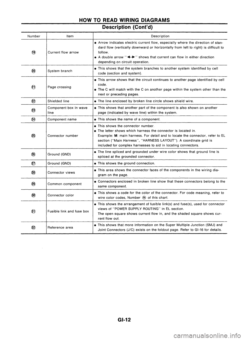
HOWTOREAD WIRING DIAGRAMS
Description (Cont'd)
Number Item Description
• Arrow indicates electriccurrentflow,especially wherethedirection ofstan-
dard flow(vertically downward orhorizontally fromlefttoright) isdifficult to
@)
Current
flowarrow follow.
• Adouble arrow" ...."shows thatcurrent canflow ineither direction
depending oncircuit operation .
@)
System
branch •
This shows thatthesystem branches toanother systemidentified bycell
code (section andsystem) .
• This arrow shows thatthecircuit continues toanother pageidentified bycell
@
code.
Page crossing
•The Cwill match withtheCon another pagewithin thesystem otherthanthe
next orpreceding pages.
@
Shieldedline •
The lineenclosed bybroken linecircle shows shieldwire.
@)
Component
boxinwave •
This shows thatanother partofthe component isalso shown onanother
line page
(indicated bywave line)within thesystem.
@
Component
name •This shows thename ofacomponent.
• This shows theconnector number.
• The letter shows whichharness theconnector islocated in.
@)
Connector
number Example:
M:main harness. Fordetail andtolocate theconnector, refertoEL
section ("MainHarness", "HARNESS LAYOUT").Acoordinate gridis
included forcomplex harnesses toaid inlocating connectors .
@
Ground
(GND) •
The linespliced andgrounded underwirecolor shows thatground lineis
spliced atthe grounded connector.
@
Ground
(GND) •
This shows theground connection.
@)
Connector
views •
This area shows theconnector facesofthe components inthe wiring dia-
gram onthe page .
@)
Common
component •
Connectors enclosedinbroken lineshow thatthese connectors belongtothe
same component.
@l
Connector
color •
This shows acode forthe color ofthe connector. Forcode meaning, referto
wire color codes, Number
@
ofthis chart.
• This shows thearrangement offusible link(s)andfuse(s), usedforconnector
@
views
of"POWER SUPPLYROUTING" inEL section.
Fusible linkand fuse box
Theopen square showscurrent flowin,and theshaded squareshowscur-
rent flow out.
@
Reference
area •
This shows thatmore information onthe Super Multiple Junction (SMJ)and
Joint Connectors
(J/C)
exists onthe foldout page.RefertoGI-16 fordetails.
GI-12
Page 1491 of 1701
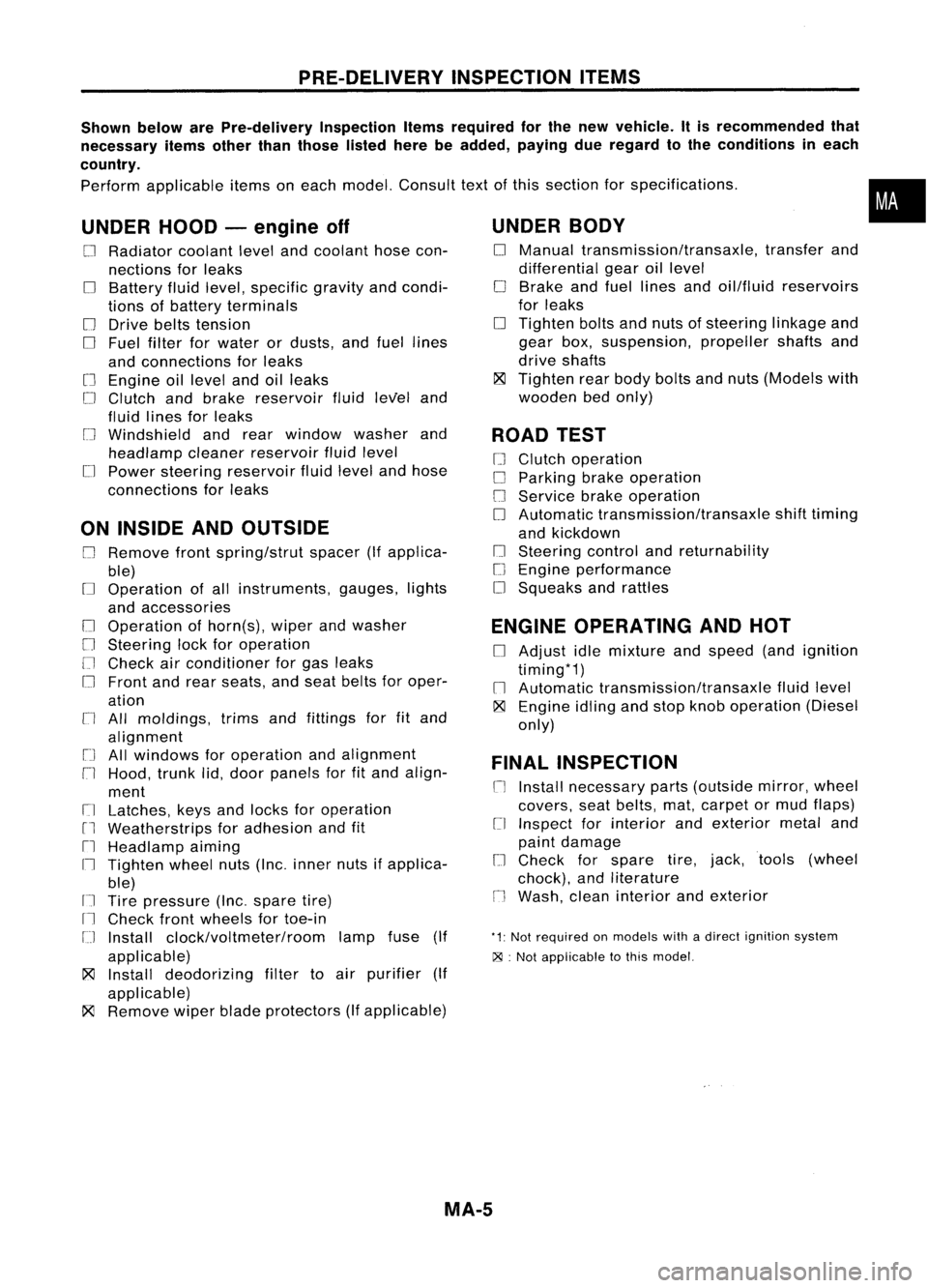
PRE-DELIVERYINSPECTIONITEMS
Shown belowarePre-delivery InspectionItemsrequired forthe new vehicle. Itis recommended that
necessary itemsotherthanthose listedherebeadded, payingdueregard tothe conditions ineach
country.
Perform applicable itemsoneach model. Consult textofthis section forspecifications .
UNDER HOOD-engine off
o
Radiator coolantlevelandcoolant hosecon-
nections forleaks
o
Battery fluidlevel, specific gravityandcondi-
tions ofbattery terminals
o
Drive beltstension
D
Fuel filter forwater ordusts, andfuel lines
and connections forleaks
[] Engine oillevel andoilleaks
D
Clutch andbrake reservoir fluidlevel and
fluid lines forleaks
o
Windshield andrear window washerand
headlamp cleanerreservoir fluidlevel
D
Power steering reservoir fluidlevel andhose
connections forleaks
ON INSIDE ANDOUTSIDE
D
Remove frontspring/strut spacer(Ifapplica-
ble)
D
Operation ofall instruments, gauges,lights
and accessories
o
Operation ofhorn(s), wiperandwasher
[] Steering lockforoperation
[] Check airconditioner forgas leaks
o
Front andrear seats, andseat belts foroper-
ation
n
All moldings, trimsandfittings forfitand
alignment
[J
Allwindows foroperation andalignment
n
Hood, trunklid,door panels forfitand align-
ment
[1
Latches, keysandlocks foroperation
rl
Weatherstrips foradhesion andfit
[l
Headlamp aiming
I~ Tighten wheelnuts(Inc. inner nutsifapplica-
ble)
IJ Tire pressure (Inc.spare tire)
Il
Check frontwheels fortoe-in
IJ Install clock/voltmeter/room lampfuse(If
applicable)
~ Install deodorizing filtertoair purifier (If
applicable)
~ Remove wiperbladeprotectors (Ifapplicable)
UNDER
BODY
o
Manual transmission/transaxle, transferand
differential gearoillevel
D
Brake andfuel lines andoil/fluid reservoirs
for leaks
D
Tighten boltsandnuts ofsteering linkageand
gear box,suspension, propellershaftsand
drive shafts
~ Tighten rearbody boltsandnuts (Models with
wooden bedonly)
ROAD TEST
D
Clutch operation
D
Parking brakeoperation
[J
Service brakeoperation
D
Automatic transmission/transaxle shifttiming
and kickdown
[] Steering controlandreturnability
o
Engine performance
D
Squeaks andrattles
ENGINE OPERATING ANDHOT
D
Adjust idlemixture andspeed (andignition
timing*1)
n
Automatic transmission/transaxle fluidlevel
~ Engine idlingandstop knob operation (Diesel
only)
FINAL INSPECTION
n
Install necessary parts(outside mirror,wheel
covers, seatbelts, mat,carpet ormud flaps)
[1
Inspect forinterior andexterior metaland
paint damage
[] Check forspare tire,jack, tools (wheel
chock), andliterature
n
Wash, cleaninterior andexterior
"1: Not required onmodels withadirect ignition system
~ :Not appiicable tothis model.
•
MA-5
Page 1651 of 1701
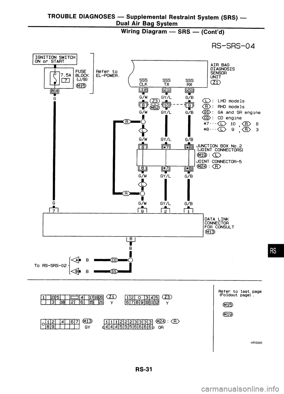
TROUBLEDIAGNOSES -Supplemental RestraintSystem(SRS)-
Dual AirBag System
Wiring Diagram -SRS -(Cont'd)
RS-SRS-04
AIR BAG
OIAGNOSIS
SENSOR
UNIT
em
:
LHOmodels
@:
GAand SReng ine
@:
CDengine
*7 ...
,
*8 ...
,
G/B
~
GY/L
~
~
G/W
t
o
•
G/W
~
SSS
SSSSSS
ClK TXRX
~ ~11
2
.°1
G/W
@
GY
IL
G/B
IciJ~
G/W
GY/L
G/B
i
II
G/W
GY/L
G/B
~ ~~JUNCTION BOXNO.2
II B.II 11*711 II*BII(JOINT CONNECTORS)
JOINT CONNECTOR-5
1*:1 II*.BI~:
GY/l
G/B
I I
FUSE
Referto
7 .5A BLOCK El-POWER.
rn
(JIB)
~
G
rtl
IGNITION
SWITCH
ON or START
4-J
B
I
To RS-SRS-02 {~B ~
i
<@-B~
•
em
Y
@
Y
Refer
tolast page
(Foldout page).
~Q@
~GY
~(M24):
~ OR
HRS006
RS-31