tire NISSAN ALMERA N15 1995 Owner's Guide
[x] Cancel search | Manufacturer: NISSAN, Model Year: 1995, Model line: ALMERA N15, Model: NISSAN ALMERA N15 1995Pages: 1701, PDF Size: 82.27 MB
Page 1638 of 1701

7.Position airbag module andtighten withnewspecial bolts.
8. Connect airbag module connector.
9. Install alllids.
10. Conduct self-diagnosis toensure entireSRSoperates prop-
erly. (Use CONSULT orwarning lampcheck.)
Before performing self-diagnosis, connectbothbattery
cables.
11. Turn steering wheeltothe leftend andthen tothe right end
fully tomake surethatspiral cableisset inthe neutral
position.
If air bag warning lampblinks orstays ON(atthe user
mode), itshows thespiral cablemaybesnapped duetoits
improper position.Performself-diagnosis again(useCON-
SUL Tor warning lamp).Ifa malfunction isdetected, replace
the spiral cablewithanew one.
SBF812EA
MRS046AA
SUPPLEMENTAL
RESTRAINTSYSTEM(SRS)
Installation -Air Bag Module andSpiral Cable
(Cont'd)
G\\
--------~
~\)
..~l~~
\\\?\\
Special bolt~~ "'(\\
cc:J
15-25 N.m ~
(1.5 -2.5 kg-m,
11 -18 ft-Ibl
Installation-Front Passenger AirBag Module
(Dual AirBag System)
• Always workfromtheside ofair bag module.
1. Install frontpassenger airbag module onsteering member.
• Ensure harness isnot caught between rearofair bag mod-
ule and steering member.
2. Install glovebox'assembly. (Gloveboxlidisopen.)
3. Connect airbag module connector tobody harness connec-
tor.
4. Close theglove boxlid.
RS-18
Page 1643 of 1701
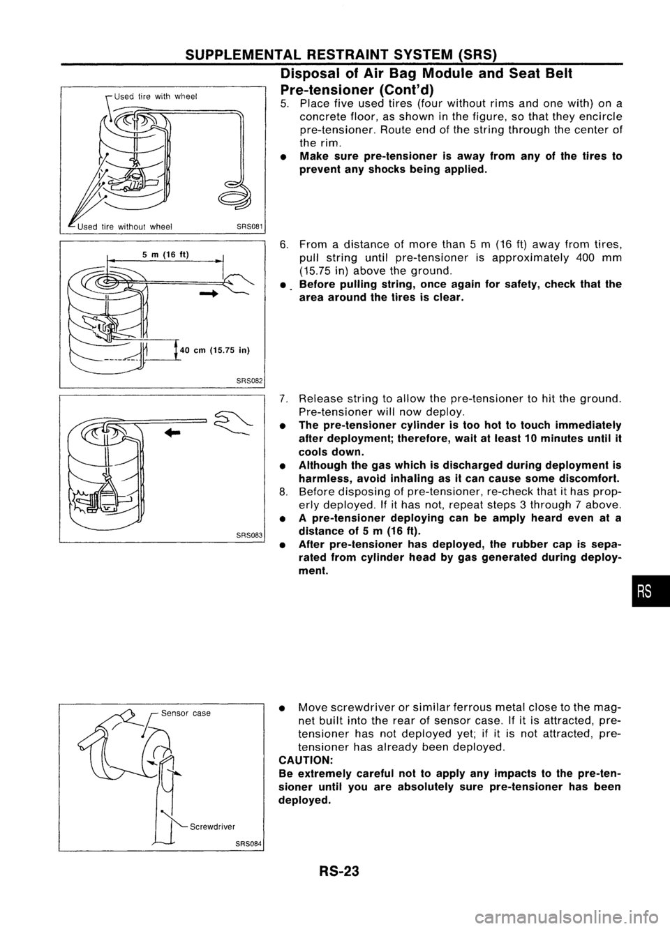
6.From adistance ofmore than5m (16
ft)
away fromtires,
pull string untilpre-tensioner isapproximately 400mm
(15.75 in)above theground.
• Before pulling string,onceagain forsafety, checkthatthe
area around thetires isclear.
SRS081
SUPPLEMENTAL
RESTRAINTSYSTEM(SRS)
Disposal ofAir Bag Module andSeat Belt
Pre-tensioner (Cont'd)
5. Place fiveused tires(four without rimsandonewith) ona
concrete floor,asshown inthe figure, sothat they encircle
pre-tensioner. Routeendofthe string through thecenter of
the rim.
• Make surepre-tensioner isaway fromanyofthe tires to
prevent anyshocks beingapplied.
40
em
(15.75
in)
5
m
(16
ft)
SRS082
SRS083
7.
Release stringtoallow thepre-tensioner tohit the ground.
Pre-tensioner willnow deploy.
• The pre-tensioner cylinderistoo hottotouch immediately
after deployment; therefore,waitatleast 10minutes untilit
cools down.
• Although thegas which isdischarged duringdeployment is
harmless, avoidinhaling asitcan cause somediscomfort.
8. Before disposing ofpre-tensioner, re-checkthatithas prop-
erly deployed. Ifithas not,repeat steps3through 7above.
• Apre-tensioner deployingcanbeamply heardevenata
distance of5m (16 ft).
• After pre-tensioner hasdeployed, therubber capissepa-
rated fromcylinder headbygas generated duringdeploy-
ment.
•
• Move screwdriver orsimilar ferrous metalclosetothe mag-
net built intotherear ofsensor case.Ifitis attracted, pre-
tensioner hasnotdeployed yet;ifit is not attracted, pre-
tensioner hasalready beendeployed.
CAUTION:
Be extremely carefulnottoapply anyimpacts tothe pre-ten-
sioner untilyouareabsolutely surepre-tensioner hasbeen
deployed.
RS-23
Page 1660 of 1701
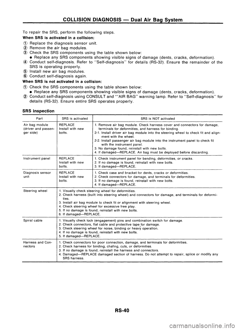
COLLISIONDIAGNOSIS -Dual AirBag System
To repair theSRS, perform thefollowing steps.
When SRSisactivated inacollision:
CD
Replace thediagnosis sensorunit.
@ Remove
theairbag modules.
@
Check theSRS components usingthetable shown below:
• Replace anySRS components showing
visible
signsofdamage (dents,cracks, deformation).
@
Conduct self-diagnosis. Referto"Self-diagnosis" fordetails (RS-32). Ensuretheremainder ofthe
SRS isoperating properly.
@
Conduct self-diagnosis again.
When SRSisnot activated inacollision:
CD
Check theSRS components usingthetable shown below:
• Replace anySRS components showingvisiblesignsofdamage (dents,cracks, deformation).
@
Conduct self-diagnosis usingCONSULT and"'AIR BAG" warning lamp.Referto"Self-diagnosis" for
details (RS-32). EnsureentireSRSoperates properly.
SRS inspection
Part SRSisactivated
SRSisNOT activated
Air bag module REPLACE
1.Remove airbag module. Checkharness coverandconnectors fordamage,
(driver andpassen-
Installwithnew terminalsfordeformities, andharness forbinding.
ger side) bolts.
2-1.Install driverairbag module intothesteering wheeltocheck fitand align-
ment withthewheel.
2-2. Install passenger airbag module intotheinstrument paneltocheck fit
with theinstrument panel.
3. No damage found,reinstall withnewbolts.
4. Ifdamaged-REPLACE. Airbag must bedeployed beforediscarding.
Instrument panel
REPLACE 1.Check instrument panelforbending, deformities, orcracks.
Install withnew
2.Ifno damage isfound, reinstall withnewbolts.
bolts. 3.Ifdamaged-REPLACE.
Diagnosis sensor REPLACE
1.Check caseandbracket fordents, cracks ordeformities.
unit Installwithnew
2.Check connectors fordamage, andterminals fordeformities.
bolts. 3.Ifno damage isfound, reinstall withnewbolts.
4. Ifdamaged-REPLACE.
Steering wheel
1.Visually checksteering wheelfordeformities.
2. Check harness (builtintosteering wheel)andconnectors fordamage, andterminals fordeformi-
ties.
3. Install airbag module tocheck fitor alignment withsteering wheel.
4. Check steering wheelforexcessive freeplay.
5. Ifno damage isfound, reinstall withnewbolts.
6. Ifdamaged-REPLACE.
Spiral cable
1.Visually checklock(engagement) pinsandcombination switchfordamage.
2. Check connectors, flatcable andprotective tapefordamage.
3. Check steering wheelfornoise, binding orheavy operation.
4. Ifno damage isfound, reinstall withnew bolts.
5. Ifdamaged-REPLACE.
Harness andCon-
1.Check connectors forpoor connection, damage,andterminals fordeformities.
nectors 2.Check harness forbinding, chafing,cuts,ordeformities.
3. Ifno damage isfound, reinstall theharness andconnectors.
4. Damaged-REPLACE damagedsectionofharness. Donot attempt torepair, spliceormodify any
SRS harness.
RS-40
Page 1665 of 1701

COLLISIONDIAGNOSIS -Single AirBag System
To repair theSRS "AIR BAG", perform thefollowing steps:
When SRSisactivated inacollision:
CD
Remove theairbag module.
@
Remove thesteering wheelassembly.
@)
Check thespiral cableusingthetable shown below:
• Ifthe spiral cableshows anyvisible damage suchasdents, cracks, ordeformation, replaceit
with anew one.
@
Install newsteering wheelassembly.
CID
Install newairbag module.
@
Conduct self-diagnosis using"AIRBAG" warning lamptoensure thatentire SRSoperates properly.
Refer toRS-43 fordetails.
When SRSisnot activated inacollision:
CD
Check theSRS components usingthetable shown below:
• Ifthe SRS components showanyvisible damage suchasdents, cracks, ordeformation, replace
them withnewones.
@
Conduct self-diagnosis using"AIRBAG" warning lamptoensure thatentire SRSoperates properly.
Refer toRS-43 fordetails.
SRS inspection
Part SRSisactivated SRSisNOT activated
Air bag module REPLACE 1.Remove airbag module. Checkharness coverandconnectors fordamage,
Install withnew terminalsfordeformities, andharness forbinding.
bolts. 2.Install airbag module intothesteering wheeltocheck fitand alignment
with thewheel.
3. No damage found,reinstall withnewbolts.
4. Ifdamaged-REPLACE. Airbag must bedeployed beforediscarding.
Steering wheel REPLACE 1.Visually checksteering wheelfordeformities.
assembly (includ- 2.Check harness andconnectors fordamage, andterminals fordeformities.
ing diagnosis sen- 3.Check diagnosis sensorunitfordents, cracks ordeformities.
sor unit).
Donot remove diagnosis sensorunitfrom steering wheel.
4. Install airbag module tocheck fitor alignment withsteering wheel.
5. Ifno damage isfound, reinstall thesteering wheelassembly.
6.
If
damaged-REPLACE.
Spiral cable 1.Check spiralcablefordents, cracks ordeformities.
2. Check connectors andprotective tapefordamage.
3. Check
steering wheelfornoise, binding orheavy operation.
4.
If
no damage isfound, reinstall withnewbolts.
5. If
damaged-REPLACE.
Harness andCon- 1.
Check connectors forpoor connection, damage,andterminals fordeformities.
nectors 2.
Check harness forbinding, chafing,cuts,ordeformities.
3. Ifno damage isfound, reinstall theharness andconnectors.
4. Damaged-REPLACE damagedsectionofharness. Donot attempt torepair, spliceormodify any
SRS harness.
RS-45
•
Page 1673 of 1701
SST491B
SST090B ON-VEHICLE
SERVICE
Bleeding Hydraulic System
1. Raise frontendofvehicle untilwheels areclear ofthe
ground.
2. Add fluid intooiltank tospecified level.Thenquickly turn
steering wheelfullytoright andleftand lightly touchsteer-
ing stoppers.
Repeat steering wheeloperation untilfluid level nolonger
decreases.
3. Start engine.
Repeat step2.above.
• Incomplete airbleeding willcause thefollowing tooccur.
When thishappens, bleedairagain.
a. Air bubbles inreservoir tank
b. Clicking noiseinoil pump
c. Excessive buzzinginoil pump
Fluid noise mayoccur inthe valve oroil pump. Thisiscommon
when thevehicle isstationary orwhile turning thesteering
wheel slowly. Thisdoes notaffect theperformance ordurabil-
ity ofthe system.
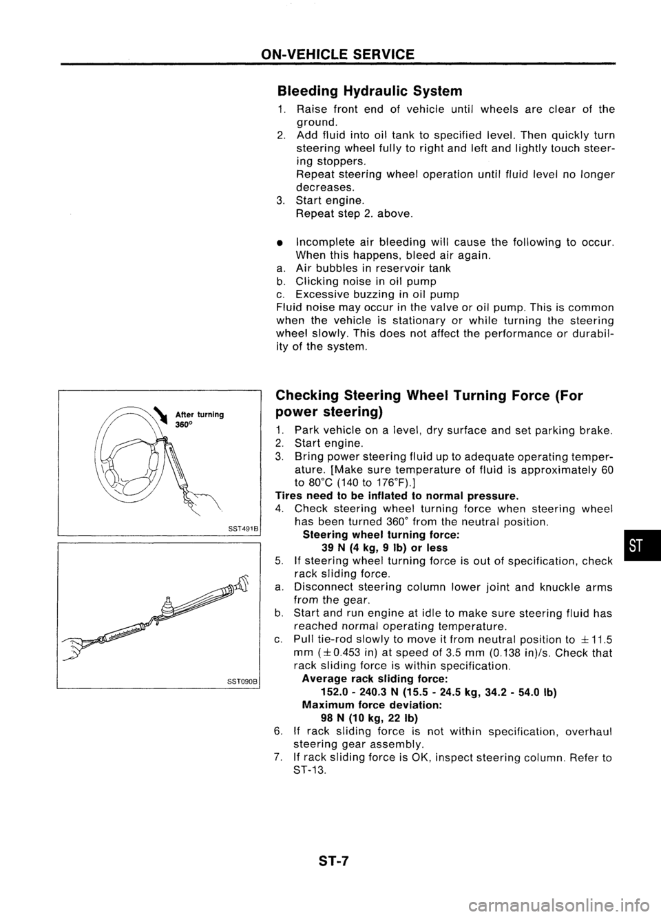
Checking SteeringWheelTurning Force(For
power steering)
1. Park vehicle onalevel, drysurface andsetparking brake.
2. Start engine.
3. Bring power steering fluiduptoadequate operating temper-
ature. [Make suretemperature offluid isapproximately 60
to 80°C (140to176°F).]
Tires needtobe inflated tonormal pressure.
4. Check steering wheelturning forcewhen steering wheel
has been turned 360°from theneutral position.
Steering wheelturning force: •
39 N(4 kg, 9Ib) orless
5.
If
steering wheelturning forceisout ofspecification, check
rack sliding force.
a. Disconnect steeringcolumnlowerjointandknuckle arms
from thegear.
b. Start andrunengine atidle tomake suresteering fluidhas
reached normaloperating temperature.
c. Pull tie-rod slowlytomove itfrom neutral position to
::l::
11.5
mm
(::l::
0.453 in)atspeed of3.5 mm (0.138 in)/s.Check that
rack sliding forceiswithin specification.
Average racksliding force:
152.0 -240.3 N(15.5 -24.5 kg,34.2 -54.0 Ib)
Maximum forcedeviation:
98 N(10 kg, 22Ib)
6.
If
rack sliding forceisnot within specification, overhaul
steering gearassembly.
7. Ifrack sliding forceisOK, inspect steering column.Referto
ST-13.
ST-7
Page 1674 of 1701
ST27091000
.. :Direction ofoil flow Low-pressure
hose SST834-AON-VEHICLE
SERVICE
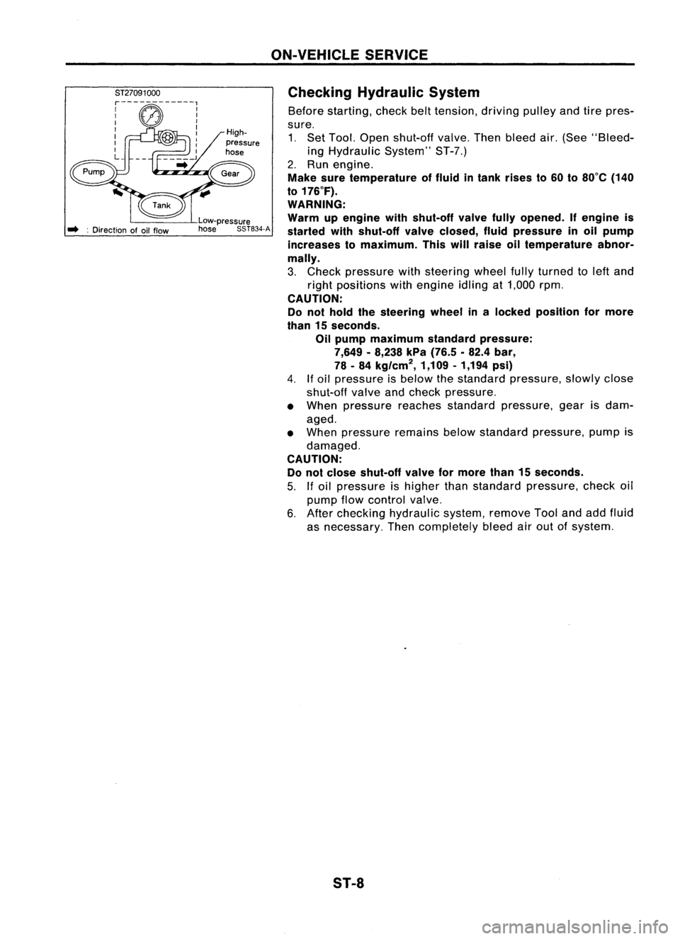
Checking Hydraulic System
Before starting, checkbelttension, drivingpulleyandtirepres-
sure. 1. Set Tool. Open shut-off valve.Thenbleed air.(See "Bleed-
ing Hydraulic System"ST-7.)
2. Run engine.
Make suretemperature offluid intank rises to60 to80°C (140
to 176°F).
WARNING:
Warm upengine withshut-off valvefullyopened. Ifengine is
started withshut-off valveclosed, fluidpressure inoil pump
increases tomaximum. Thiswillraise oiltemperature abnor-
mally.
3. Check pressure withsteering wheelfullyturned toleft and
right positions withengine idlingat1,000 rpm.
CAUTION:
Do not hold thesteering wheelinalocked position formore
than 15seconds.
Oil pump maximum standardpressure:
7,649 -8,238 kPa(76.5 .82.4 bar,
78 -84 kg/cm
2,
1,109-1,194 psi)
4.
If
oil pressure isbelow thestandard pressure, slowlyclose
shut-off valveandcheck pressure.
• When pressure reachesstandard pressure, gearisdam-
aged.
• When pressure remainsbelowstandard pressure, pumpis
damaged.
CAUTION: Do not close shut-off valveformore than15seconds.
5.
If
oil pressure ishigher thanstandard pressure, checkoil
pump flowcontrol valve.
6. After checking hydraulic system,removeToolandaddfluid
as necessary. Thencompletely bleedairout ofsystem.
S1-8
Page 1677 of 1701
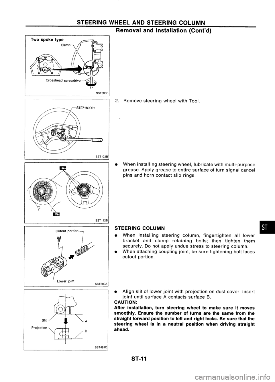
STEERINGWHEELANDSTEERING COLUMN
Removal andInstallation (Cont'd)
Two spoke type
Clamp
Crosshead screwdriver~
II
SST503C
2.Remove steering wheelwithTool.
SST122B
Cr~I~I;~
~#f
~.'".
Lowerjoint
SST112B
SST800A
•
When installing steeringwheel,lubricate withmulti-purpose
grease. Applygrease toentire surface ofturn signal cancel
pins andhorn contact sliprings.
STEERING COLUMN
• When installing steeringcolumn,fingertighten alllower
bracket andclamp retaining bolts;thentighten them
securely. Donot apply undue stress tosteering column.
• When attaching couplingjoint,besure tightening boltfaces
cutout portion.
• Align slitoflower jointwithprojection ondust cover. Insert
joint untilsurface Acontacts surfaceB.
CAUTION:
After installation, turnsteering wheeltomake sureitmoves
smoothly. Ensurethenumber ofturns arethesame fromthe
straight forward position toleft and right locks. Besure thatthe
steering wheelisin aneutral position whendriving straight
ahead.
•
SST491C ST-11
Page 1694 of 1701
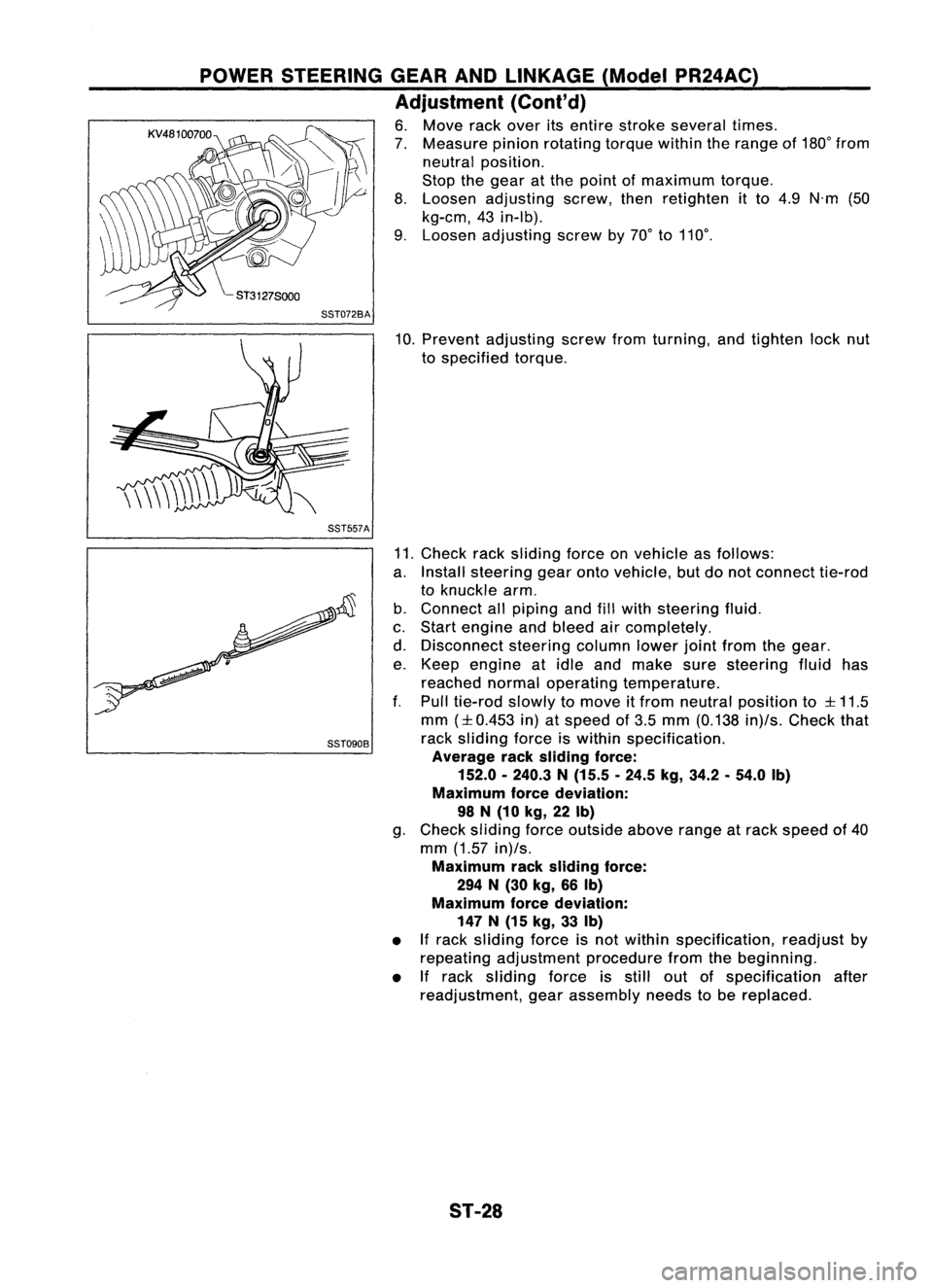
POWERSTEERING GEARANDLINKAGE (ModelPR24AC)
Adjustment (Cont'd)
6. Move rackover itsentire stroke several times.
7. Measure pinionrotating torquewithintherange of180° from
neutral position.
Stop thegear atthe point ofmaximum torque.
8. Loosen adjusting screw,thenretighten itto 4.9 N'm (50
kg-em, 43in-Ib).
9. Loosen adjusting screwby70° to110°.
SST072BA
10.Prevent adjusting screwfromturning, andtighten locknut
to specified torque.
SST557A
SST090B
11.
Check racksliding forceonvehicle asfollows:
a. Install steering gearontovehicle, butdonot connect tie-rod
to knuckle arm.
b. Connect allpiping andfillwith steering fluid.
c. Start engine andbleed aircompletely.
d. Disconnect steeringcolumnlowerjointfrom thegear.
e. Keep engine atidle and make suresteering fluidhas
reached normaloperating temperature.
f. Pull tie-rod slowlytomove itfrom neutral position to
:l:
11.5
mm
(:l:
0.453 in)atspeed of3.5 mm (0.138 in)/s.Check that
rack sliding forceiswithin specification.
Average racksliding force:
152.0 -240.3 N(15.5 .24.5 kg,34.2.54.0 Ib)
Maximum forcedeviation:
98 N(10 kg,22Ib)
g. Check sliding forceoutside aboverangeatrack speed of40
mm (1.57 in)/s.
Maximum racksliding force:
294 N(30 kg, 66Ib)
Maximum forcedeviation:
147 N(15 kg, 33Ib)
• Ifrack sliding forceisnot within specification, readjustby
repeating adjustment procedurefromthebeginning.
• If
rack sliding forceisstill outofspecification after
readjustment, gearassembly needstobe replaced.
ST-28