tire NISSAN ALMERA N15 1995 User Guide
[x] Cancel search | Manufacturer: NISSAN, Model Year: 1995, Model line: ALMERA N15, Model: NISSAN ALMERA N15 1995Pages: 1701, PDF Size: 82.27 MB
Page 717 of 1701
SFE180A
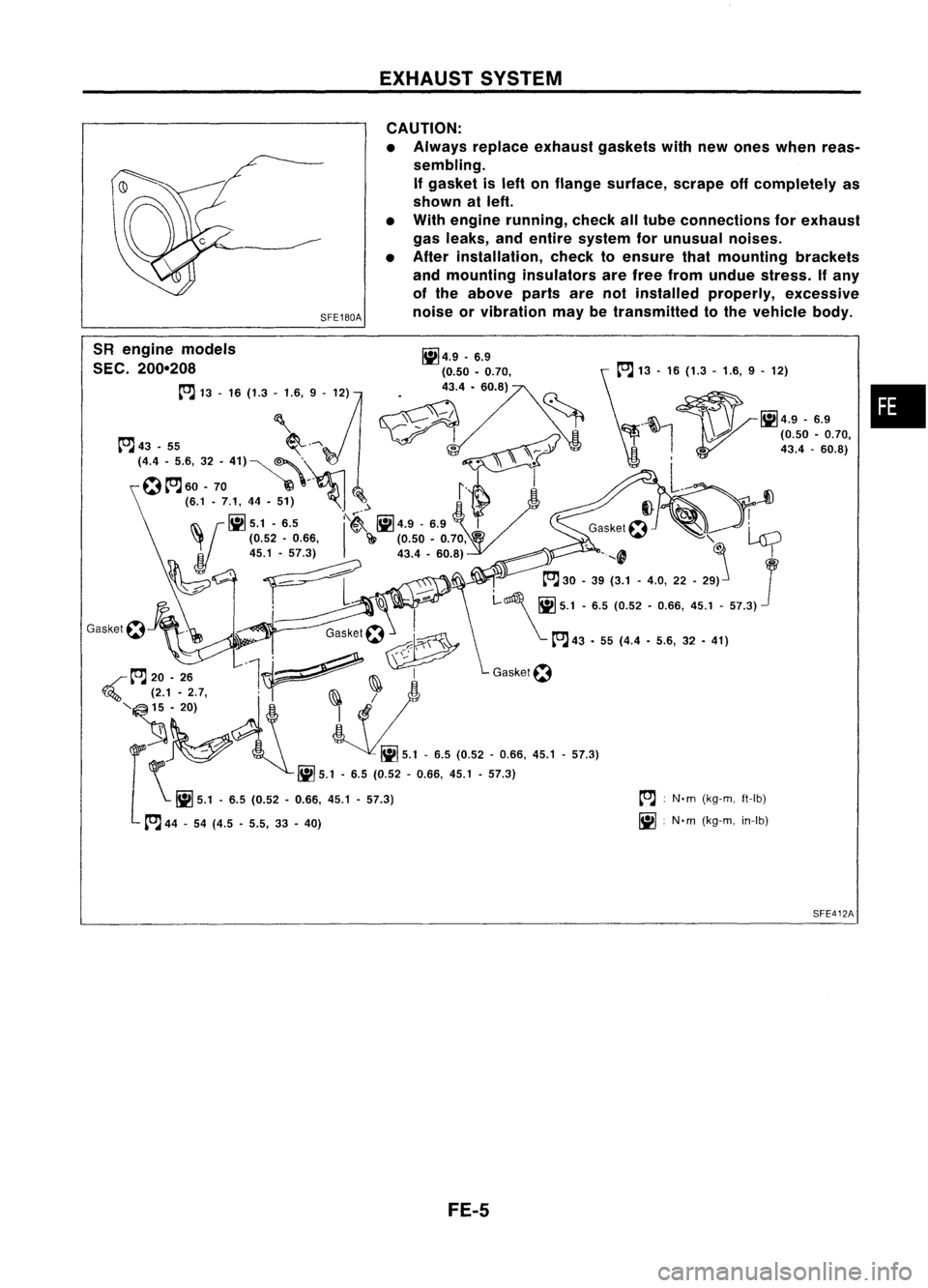
SR engine models
SEC. 200-208
toJ
13-16 (1.3 -1.6, 9-12)
EXHAUST
SYSTEM
CAUTION:
• Always replace exhaust gasketswithnewones when reas-
sembling. If gasket isleft onflange surface, scrapeoffcompletely as
shown atleft.
• With engine running, checkalltube connections forexhaust
gas leaks, andentire system forunusual noises.
• After installation, checktoensure thatmounting brackets
and mounting insulators arefree from undue stress.
If
any
of the above partsarenotinstalled properly, excessive
noise orvibration maybetransmitted tothe vehicle body.
GaSket~
toJ:
N'm (kg-m, ft-Ib)
~ :N'm (kg-m, in-Ib)
SFE412A
FE-5
•
Page 820 of 1701
TROUBLEDIAGNOSIS FORDTC12
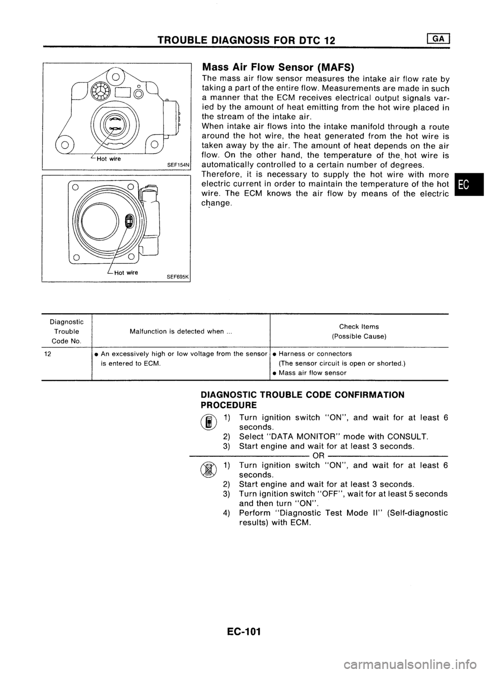
Mass AirFlow Sensor (MAFS)
The mass airflow sensor measures theintake airflow rateby
taking apart ofthe entire flow.Measurements aremade insuch
a manner thattheECM receives electrical outputsignals var-
ied bythe amount ofheat emitting fromthehotwire placed in
the stream ofthe intake air.
When intake airflows intotheintake manifold througharoute
around thehotwire, theheat generated fromthehotwire is
taken awaybythe air.The amount ofheat depends onthe air
flow. Onthe other hand, thetemperature ofthe ..hot wire is
SEF154N
automatically controlledtoacertain number ofdegrees.
Therefore, itis necessary tosupply thehotwire withmore •
electric currentinorder tomaintain thetemperature ofthe hot
wire. TheECM knows theairflow bymeans ofthe electric
c~ange.
SEF695K
Diagnostic Trouble
Code No. Malfunction
isdetected when... Check
Items
(Possible Cause)
12
•
An excessively highorlow voltage fromthesensor •Harness orconnectors
is entered toECM. (Thesensor circuitisopen orshorted.)
• Mass airflow sensor
DIAGNOSTIC TROUBLECODECONFIRMATION
PROCEDURE
rif\
1)Turn ignition switch"ON",andwait foratleast 6
~ seconds.
2) Select "DATA MONITOR" modewithCONSULT.
3) Start engine andwait foratleast 3seconds.
----------OR ----------
r
~ seconds.
2) Start engine andwait foratleast 3seconds.
3) Turn ignition switch"OFF", waitforatleast 5seconds
and then turn"ON".
4) Perform "Diagnostic TestMode II"(Self-diagnostic
results) withECM.
EC-101
Page 1012 of 1701

TROUBLEDIAGNOSIS FOROTe12
•
Check
Items
(Possible Cause)
Mass
AirFlow Sensor (MAFS)
The mass airflow sensor isplaced inthe stream ofintake air.
It measures theintake flowratebymeasuring apart ofthe
entire intake flow.Itconsists ofahot wire thatissupplied with
electric currentfromtheECM. Thetemperature ofthe hotwire
is controlled bythe ECM acertain amount. Theheat generated
by the hotwire isreduced asthe intake airflows around it.The
more air,thegreater theheat loss.
Therefore, theECM mustsupply moreelectric currenttomain-
tain thetemperature ofthe hotwire asair flow increases. The
SEF781K
ECMdetects theairflow bymeans ofthis current change.
Malfunction isdetected when...
Diagnostic
Trouble
Code No.
12
•An excessively highorlow voltage fromthesensor •Harness orconnectors
is sent toECM. (Thesensor circuitisopen orshorted.)
• Mass airflow sensor
DIAGNOSTIC TROUBLECODECONFIRMATION
PROCEDURE
fiii\
1)Turn ignition switch"ON",andwait atleast 6sec-
~ onds.
2) Select "DATA MONITOR" modewithCONSULT.
3) Start engine andwait atleast 3seconds.
---------- OR----------
rR\
1)Turn ignition switch"ON",andwait atleast 6sec-
~ onds.
2) Start engine andwait atleast 3seconds.
3) Turn ignition switch"OFF", waitatleast 7seconds
and then turn"ON".
4) Perform "Diagnostic TestMode II"(Self-diagnostic
results) withECM.
EC-293
Page 1113 of 1701
![NISSAN ALMERA N15 1995 User Guide TROUBLEDIAGNOSES
Quick-glow System(Cont'd)
~
ill]
SEF941P
Ii]
~i5
Glow
Eill~
plug
0
@]Q]
2
[ill
~SEF942P INSPECTION
START
Check fuellevel, fuelsupplying system,
~Correct.
starter motor](/img/5/57349/w960_57349-1112.png "NISSAN ALMERA N15 1995 User Guide TROUBLEDIAGNOSES
Quick-glow System(Cont'd)
~
ill]
SEF941P
Ii]
~i5
Glow
Eill~
plug
0
@]Q]
2
[ill
~SEF942P INSPECTION
START
Check fuellevel, fuelsupplying system,
~Correct.
starter motor")
TROUBLEDIAGNOSES
Quick-glow System(Cont'd)
~
ill]
SEF941P
Ii]
~i5
Glow
Eill~
plug
0
@]Q]
2
[ill
~SEF942P INSPECTION
START
Check fuellevel, fuelsupplying system,
~Correct.
starter motor,etc.
OK
m
Check thatallglow plugconnecting
~Installproperly.
plate nutsareinstalled properly.
OK
CHECK OVERALL FUNCTION. OK
CHECK COMPONENT
Check entirequick-glow system.(Refer
---..
(Glowplug).
to "System Operation Check"onnext See
page EC-397.
page.)
NG
CHECK POWER SUPPLY ANDGROUND NG
Repair harness orcon-
CIRCUIT.
---..
nector.
(Refer to"Power Supplyandground
circuit forECM", EC-396).
OK
(!]
CHECK VOLTAGE BETWEEN GLOW NG
Check thefollowing.
RELA YAND GROUND.
---..
•7.5A fuse
1) Check voltage between terminals •
75A fusible link
G), @and ground withtester. •Harness continuity
Voltage: Batteryvoltage between
glowrelay
OK and
fuse
If NG, repair harness or
connectors.
[!1
CHECK OUTPUT SIGNALCIRCUIT. NG
Repair harness orcon-
1) Check harness continuity between
---+
nectors.
ECM terminal
@
andterminal @.
Continuity shouldexist.
OK
Ii]
CHECK HARNESS CONTINUITY NG
Repair harness orcon-
BETWEEN GLOWRELAY ANDGLOW
---+
nectors.
PLUG. 1) Disconnect ECMharness connector.
2) Disconnect glowrelay.
3) Check harness continuity between
glow relay terminal
@
and glow
plug.
Continuity shouldexist.
~OK
SEF940P
SEF939P
-"-.....
'y;-----...
Connecting platenut:J
~1.0 •1.5
N.mr-
"(0.1 •0.15 kg-m,- ""'-
8.7 -13.0 in-Ib)
~
""
.
'------
~
~
ECM
E1
CONNECTOR
II
106
II
(!]
~io
EC-394
Page 1167 of 1701

•
less
than 0.18(0.0071)
0.12
-0.20 (0.0047 -0.0079)
0.05 -0.09 (0.0020 -0.0035)
0.05 -0.11 (0.0020 -0.0043)
0.05 -0.09 (0.0020 -0.0035)
Body
toouter gearclearance
CD
Outer geartoinner gearclearance
@
Housing toinner gearclearance @
Housing toouter gearclearance
@
Inner geartohousing clearance @
If
itexceeds thelimit, replace gearsetorentire oilpump
assembly.
SLC560A
ENGINE
LUBRICATION SYSTEM
Oil Pump (Cont'd)
INSPECTION
Using afeeler gauge, checkthefollowing clearances.
Unit:mm(in)
SLC561C
SLC568A REGULATOR VALVEINSPECTION
1. Visually inspectcomponents forwear anddamage.
2. Check oilpressure regulator valvesliding surface andvalve
spring.
3. Coat regulator valvewithengine oil.Check that
it
falls freely
into thevalve holebyitsown weight.
If
damaged, replaceregulator valvesetoroil pump assembly.
SLC049B LC-29
Page 1224 of 1701
ENGINEREMOVAL
WARNING:
a. Situate vehicle onaflat and solid surface.
b. Place chocks atfront andback ofrear wheels.
c. Donot remove engineuntilexhaust systemhascompletely
cooled off.
Otherwise, youmay burn yourself and/orfiremay break out
in fuel line.
d. For safety during subsequent steps,thetension ofwires
should beslackened againsttheengine.
e. Before disconnecting fuelhose, release fuelpressure from
fuel line.
Refer to"Releasing FuelPressure" inEC section.
f. Besure tohoist engine andtransaxle inasafe manner.
g. For engines notequipped withengine slingers, attach
proper slingers andbolts described inPARTS CATALOG.
CAUTION:
• When liftingengine, besure toclear surrounding parts.
Take special careforaccelerator wirecasing, brakelines
and brake master cylinder.
• Inhoisting theengine, alwaysuseengine slingers inasafe
manner.
• Inremoving driveshaft, becareful nottodamage grease
seal oftransaxle.
Engine cannotberemoved separately fromtransaxle. Remove
engine withtransaxle.
Removal
1. Drain water.
2. Remove hood.
3. Remove battery.
4. Remove reservoir tankandbracket.
5. Remove drivebelts.
6. Remove alternator, compressor andpower steering oil
pump fromengine.
Power steering pumpdoesnotneed tobe disconnected from
power steering tubes.
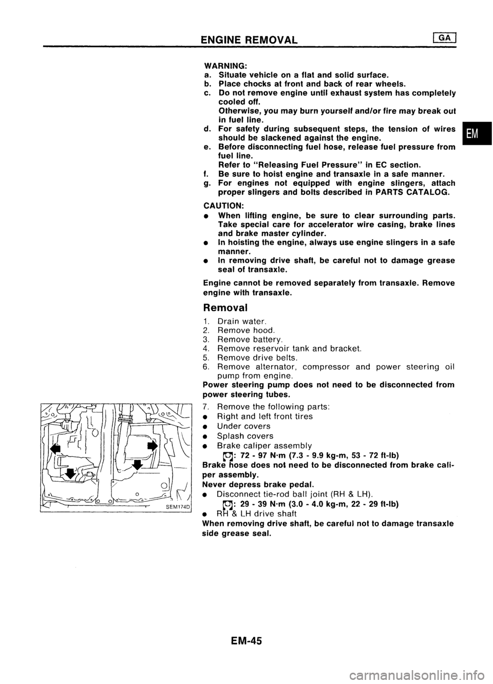
7. Remove thefollowing parts:
• Right andleftfront tires
• Under covers
• Splash covers
• Brake caliper assembly
~: 72-97 N'm (7.3•9.9 kg-m, 53•72 ft-Ib)
Brake hosedoes notneed tobe disconnected frombrake cali-
per assembly.
Never depress brakepedal.
• Disconnect tie-rodballjoint (RH
&
LH).
~: 29-39 N'm (3.0-4.0 kg-m, 22-29 ft-Ib)
• RH
&
LH drive shaft
When removing driveshaft, becareful nottodamage transaxle
side grease seal.
EM-45
•
Page 1355 of 1701
GENERALINFORMATION •
SECTION
G
I
CONTENTS
PRECAUTIONS 2
Supplemental RestraintSystem(SRS)"AIR
BAG" (DualAirBag System) 2
Supplemental RestraintSystem(SRS)"AIR
BAG" (Single AirBag System) 2
Precautions forNATS V2.0(ForGasoline
Engine Model) 3
General Precautions 3
Precautions forMultiport FuelInjection
System orECCS Engine 5
Precautions forThree WayCatalyst 5
Engine Oils 5
Precautions forFuel 6
HOW TOUSE THIS
MANUAL 7
HOW TOREAD WIRING DIAGRAMS 9
Sample/Wiring Diagram-EXAMPL - 9
Description 11
Wiring Diagram Codes(CellCodes) 17
HOW TOPERFORM EFFICIENT DIAGNOSIS FOR
AN ELECTRICAL INCIDENT 18
Work Flow 18
Incident Simulation Tests 19
Circuit Inspection 23
HOW
TOFOLLOW FLOWCHART INTROUBLE
DIAGNOSES 29
CONSULT CHECKING SYSTEM
32
Function andSystem Application 32
Lithium BatteryReplacement.. 32
Checking Equipment 32
IDENTIFICATION INFORMATION 33
Model Variation 33
Identification Number 36
Di mens ions 39
Wheels andTires 39
LIFTING POINTSANDTOW TRUCK TOWING ..40
Preparation 40
Board-on
Lift
40
Garage JackandSafety Stand 41
2-pole Lift 42
Tow Truck Towing 43
TIGHTENING TORQUEOFSTANDARD BOLTS
44
SAE J1930 TERMINOLOGY LIST 45
SAE J1930 Terminology List.. 45
Page 1358 of 1701
SEF289HSGI233
SGI234 PRECAUTIONS
General Precautions (Cont'd)
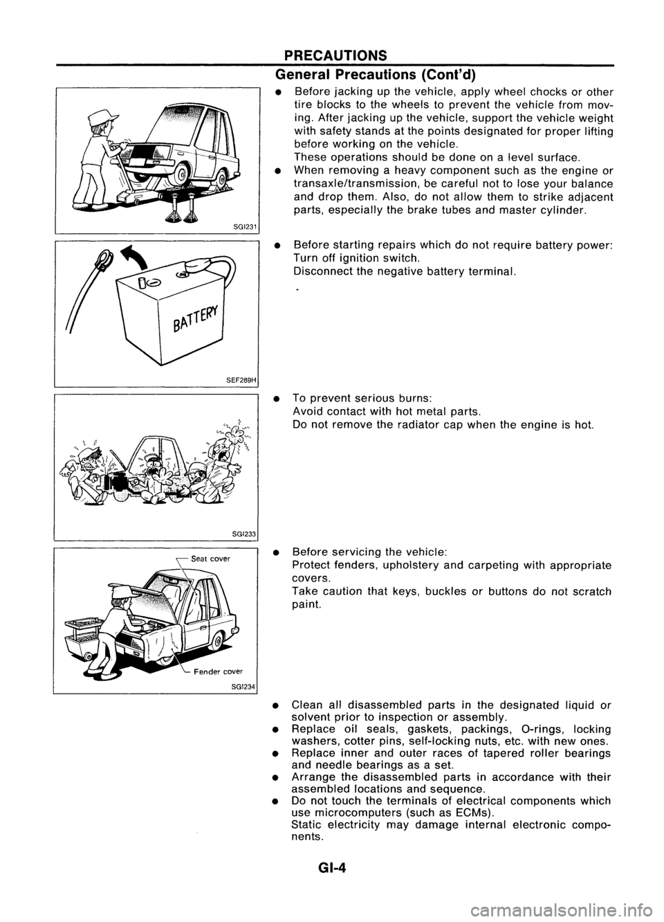
• Before jacking upthe vehicle, applywheel chocks orother
tire blocks tothe wheels toprevent thevehicle frommov-
ing. After jacking upthe vehicle, supportthevehicle weight
with safety stands atthe points designated forproper lifting
before working onthe vehicle.
These operations shouldbedone onalevel surface.
• When removing aheavy component suchasthe engine or
transaxle/transmission, becareful nottolose your balance
and drop them. Also,donot allow themtostrike adjacent
parts, especially thebrake tubesandmaster cylinder.
• Before starting repairswhichdonot require batterypower:
Turn offignition switch.
Disconnect thenegative batteryterminal.
• Toprevent seriousburns:
Avoid contact withhotmetal parts.
Do not remove theradiator capwhen theengine ishot.
• Before servicing thevehicle:
Protect fenders, upholstery andcarpeting withappropriate
covers.
Take caution thatkeys, buckles orbuttons donot scratch
paint.
• Clean alldisassembled partsinthe designated liquidor
solvent priortoinspection orassembly.
• Replace oilseals, gaskets, packings, O-rings,locking
washers, cotterpins,self-locking nuts,etc.with newones.
• Replace innerandouter races oftapered rollerbearings
and needle bearings asaset.
• Arrange thedisassembled partsinaccordance withtheir
assembled locationsandsequence.
• Donot touch theterminals ofelectrical components which
use microcomputers (suchasECMs).
Static electricity maydamage internalelectronic compo-
nents.
GI-4
Page 1393 of 1701
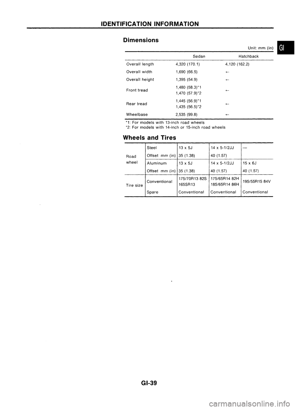
IDENTIFICATIONINFORMATION
Dimensions SedanUnit:
mm(in) •
Hatchback
Overall length
Overall width
Overall height
Front tread
Rear tread
Wheelbase 4,320
(170.1)
1,690 (66.5)
1,395 (54.9)
1,480 (58.3)* 1
1,470 (57.9)*2
1,445 (56.9)*1
1,435 (56.5)*2
2,535 (99.8) 4,120
(162.2)
*1: For models with13-inch roadwheels
*2: For models with14-inch or15-inch roadwheels
Wheels andTires
Steel 13x5J 14x5-1/2JJ
-
Road Offset
mm(in) 35(1.38) 40(1.57)
wheel Aluminum 13x5J 14
x5-1/2JJ 15x6J
Offset mm(in)
35(1.38) 40
(1.57) 40(1.57)
175170R1382S 175/65R1482H
195/55R1584V
Conventional
185/65R1486H
Tire size 165SR13
Spare Conventional
Conventional Conventional
GI-39
Page 1481 of 1701
Pulleyassembly SERVICE
PROCEDURES
Compressor Clutch(Cont'd)
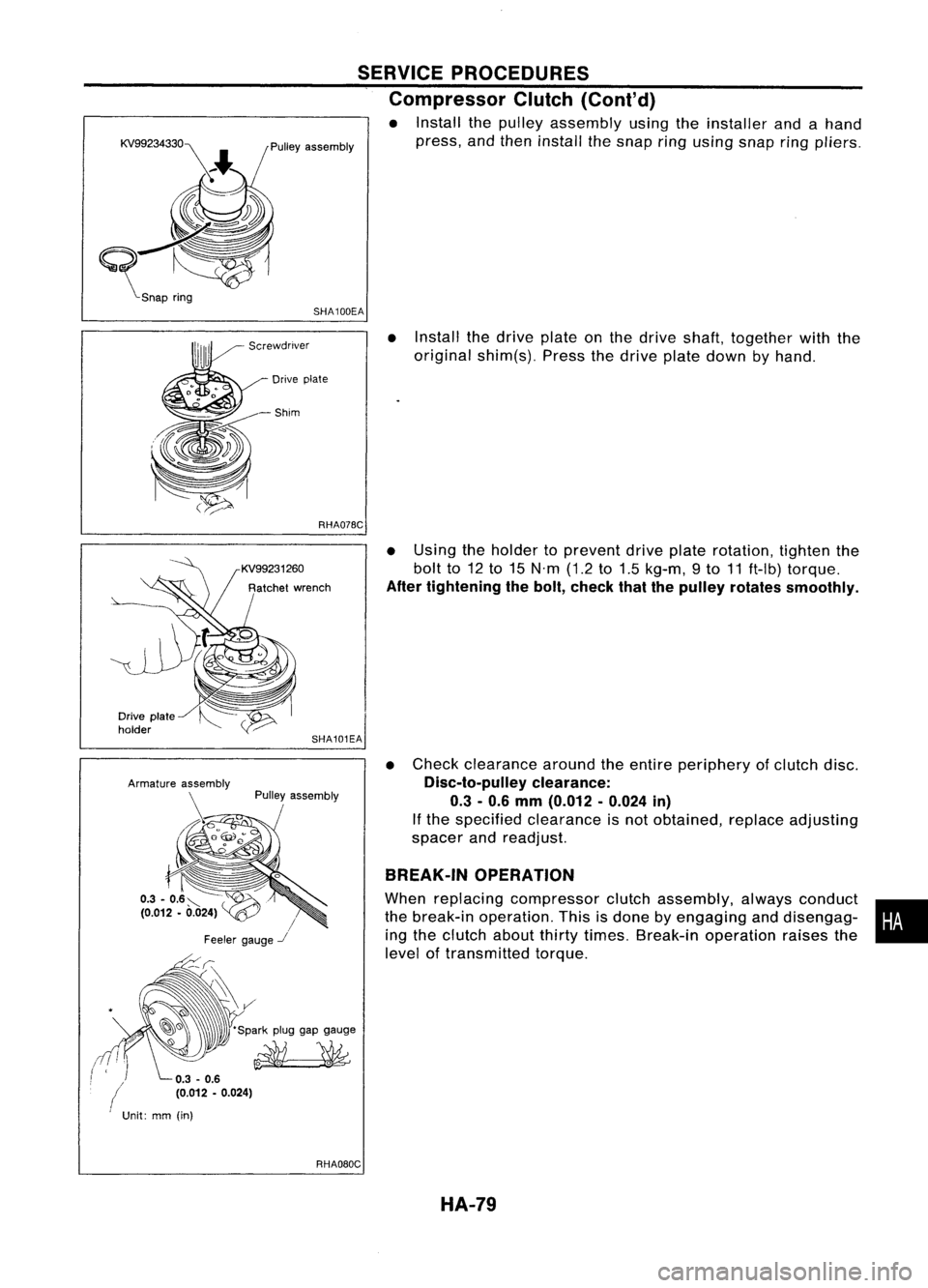
• Install thepulley assembly usingtheinstaller andahand
press, andthen install thesnap ringusing snapring
pliers.
SHA100EA
•Install thedrive plateonthe drive shaft, together withthe
original shim(s). Pressthedrive platedown byhand.
Drive plate
-Shim
RHA07BC
•Using theholder toprevent driveplaterotation, tightenthe
bolt to12to15 N'm (1.2to1.5 kg-m, 9to 11ft-Ib) torque.
After tightening thebolt, check thatthepulley rotates smoothly.
• Check clearance aroundtheentire periphery ofclutch disc.
Disc-to-pulley clearance:
0.3 -0.6 mm (0.012 -0.024 in)
If the specified clearance isnot obtained, replaceadjusting
spacer andreadjust.
BREAK-IN OPERATION
When replacing compressor clutchassembly, alwaysconduct •
the break-in operation. Thisisdone byengaging anddisengag-
i
ing the clutch aboutthirtytimes. Break-in operation raisesthe
level oftransmitted torque.
SHA101EA
Pulley assembly
/
Feeler gauge
-.I
-~~ 'Sparkpluggapgauge
~
Drive
plate
holder
(
Unit:mm(in)
RHAOBOCHA-79