tow NISSAN ALMERA N15 1995 Owner's Guide
[x] Cancel search | Manufacturer: NISSAN, Model Year: 1995, Model line: ALMERA N15, Model: NISSAN ALMERA N15 1995Pages: 1701, PDF Size: 82.27 MB
Page 953 of 1701

ENGINEANDEMISSION BASICCONTROL SYSTEMDESCRIPTION [][]
Multiport FuelInjection (MFI)System (Cont'd)
CLOSED LOOP MIXTURERATIOFEEDBACK CONTROL(CLOSEDLOOP
CONTROL CONTROL)
The mixture ratiofeedback systemprovides thebest air-fuel
Feedback signal
mixtureratiofordriveability andemission control.Thethree
way catalyst canthen better reduce CO,HCand NOx emissions.
This system usesaheated oxygen sensorinthe exhaust man-
ifold tomonitor ifthe engine operation isrich orlean. TheECM
adjusts theinjection pulsewidthaccording tothe sensor volt-
age signal. Formore information abouttheheated oxygen
sensor, refertoEC-362. Thismaintains themixture ratiowithin
MEF025DD
therange ofstoichiometric (idealair-fuel mixture).
This stage isreferred toas the closed loopcontrol condition.
OPEN LOOPCONTROL
The open loopsystem condition referstowhen theECM detects
any ofthe following conditions. Feedbackcontrolstopsinorder
to maintain stabilized fuelcombustion.
• Deceleration andacceleration
• High-load, high-speed operation
• Engine idling
• Malfunction ofheated oxygen sensororits circuit
• Insufficient activationofheated oxygen sensoratlow
engine coolant temperature
• High-engine coolanttemperature
• After shifting from"N"to"0"
• During warm-up
• When starting theengine
MIXTURE RATIOSELF-LEARNING CONTROL
The mixture ratiofeedback controlsystem monitors themixture
ratio signal transmitted fromtheheated oxygen sensor. This
feedback signalisthen senttothe ECM. TheECM controls the
basic mixture ratioasclose tothe theoretical mixtureratioas
possible. However, thebasic mixture ratioisnot necessarily con-
trolled asoriginally designed. Bothmanufacturing differences
(Le., mass airflow sensor hotwire) andcharacteristic changes
during operation (Le.,injector clogging) directlyaffectmixture
ratio.
Accordingly, thedifference betweenthebasic andtheoretical
mixture ratiosismonitored inthis system. Thisisthen com-
puted interms of"injection pulseduration" toautomatically
compensate forthe difference betweenthetwo ratios.
EC-234
Page 958 of 1701

EVAPORATIVEEMISSIONSYSTEM
Inspection (Conl'd)
FUEL CHECK VALVE
Fuel tank side
+
0:>
Fuel lankside
QAir
.. Fuel vapor
EVAP canister side
..
MEC744B
SEF427N Check
valveoperation
1. Blow airthrough connector onfuel tank side.
A considerable resistanceshouldbefelt and aportion ofair
flow should bedirected towardtheEVAP canister side.
2. Blow airthrough connector onEVAP canister side.
Air flow should besmoothly directedtowardfueltank side.
3. Iffuel check valveissuspected ofnot properly functioning
in steps 1and 2above, replace it.
FUEL TANK VACUUM RELIEFVALVE
1. Wipe clean valvehousing.
4.
Suck airthrough thecap. Aslight resistance accompanied
by valve clicks indicates thatvalve Ais ingood mechanical
condition. Notealsothat, byfurther sucking air,the resis-
tance should disappear withvalve clicks.
3. Blow aironfuel tank sideandensure thatcontinuity ofair
passage existsthrough valveB.
4. Ifvalve isclogged orifno resistance isfelt, replace capas
an assembly.
EC-239
•
Page 976 of 1701

ON-BOARDDIAGNOSTIC SYSTEMDESCRIPTION
CONSULT (Cont'd)
SELF-DIAGNOSTIC MODE
Regarding itemsdetected in"SELF-DiAG RESULTS"mode,referto"Diagnostic TroubleCode(DTC)
Chart". (Seepage EC-268.)
DATA MONITOR MODE
Monitored item ECM
Main
[Unit] input
signals Description
Remarks
signals
CMPS.RPM •Indicates theengine speedcomputed •
Accuracy becomespoorifengine
(REF) [rpm] fromtheREF signal (180'signal) of speeddropsbelow theidle rpm.
0 0
the
camshaft positionsensor. •
Ifthe signal isinterrupted whilethe
engine isrunning, anabnormal value
may beindicated .
MAS AIR/FL SE[V]
0 0
•
The sig~al voltage ofthe mass air •
When theengine isstopped, acertain
flow sensor isdisplayed. valueisindicated .
COOLAN TEMP/S •
The engine coolant temperature •
When theengine coolant temperature
rOC] orrF] (determined
bythe signal voltage ofsensor
isopen orshort-circuited,
0 0
the
engine coolant temperature sen-ECMenters fail-safe mode.The
sor) isdisplayed. engine
coolant temperature deter-
mined bythe ECM isdisplayed .
02
SEN [V]
00
•
The signal voltage ofthe heated oxy-
gen sensor isdisplayed.
M/R F/CMNT •
Display ofheated oxygen sensorsig-•
After turning ONthe ignition switch,
[RICH/LEAN] nal
during air-fuel ratiofeedback con-"RICH"
isdisplayed untilair-fuel mix-
trol: ture
ratio feedback controlbegins.
RICH ...means themixture became •
When theair-fuel ratiofeedback is
0 0
"rich",
andcontrol isbeing affected clamped,
thevalue justbefore the
toward aleaner mixture. clamping
isdisplayed continuously.
LEAN ...means themixture became
"lean", andcontrol isbeing affected
toward arich mixture .
VHCL SPEED SE •
The vehicle speedcomputed fromthe
[km/h] or[mph]
00
vehicle
speedsensor signalisdis-
played .
SA TTERY VOLT[V]
0 0
•
The power supply voltage ofECM is
displayed .
THRTL POSSEN [V]
0 0
•
The throttle position sensorsignal
voltage isdisplayed.
START SIGNAL •
Indicates [ON/OFF] conditionfromthe•
After starting theengine, [OFF]isdis-
[ON/OFF]
00
starter
signal. played
regardless ofthe starter sig-
nal.
CLSD THLIPOSI •
Indicates theclosed throttle position
[ON/OFF] [ON/OFF]
determined bythe throttle
0 0
position
sensorsignal.
ON: Closed throttle position
OFF: Other thanclosed throttle
position
NOTE:
Any monitored itemthatdoes notmatch thevehicle beingdiagnosed isdeleted fromthedisplay auto-
matically.
EC-257
•
Page 986 of 1701
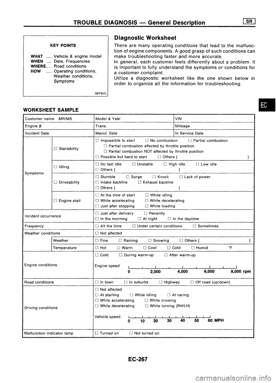
TROUBLEDIAGNOSIS -General Description
KEY POINTS
WHAT .....
Vehicle &engine model
WHEN
Date,Frequencies
WHERE Roadconditions
HOW Operatingconditions,
Weather conditions,
Symptoms
SEF907L
WORKSHEET SAMPLE Diagnostic
Worksheet
There aremany operating conditions thatlead tothe malfunc-
tion ofengine components. Agood grasp ofsuch conditions can
make troubleshooting fasterandmore accurate.
In
general, eachcustomer feelsdifferently aboutaproblem. It
is important tofully understand thesymptoms orconditions for
a customer complaint.
Utilize adiagnostic worksheet liketheone shown belowin
order toorganize allthe information fortroubleshooting.
•
Customer name
MR/MS Model
&
Year VIN
Engine
#
Trans. Mileage
Incident Date Manuf.Date InService Date
o
Impossible tostart
o
No combustion
o
Partial combustion
o
Startability
o
Partial combustion affectedbythrottle position
o
Partial combustion NOTaffected bythrottle position
o
Possible buthard tostart
o
Others [
]
o
No fast idle
o
Unstable
o
High idle
o
Low idle
[J
Idling
o
Others [
]
Symptoms
[J
Stumble
o
Surge
o
Knock
o
Lack ofpower
o
Driveability
o
Intake backfire
o
Exhaust backfire
o
Others [
]
o
At the time ofstart
o
While idling
o
Engine stall
o
While accelerating
o
While decelerating
o
Just after stopping
o
While loading
Incident occurrence
o
Just after delivery
o
Recently
o
Inthe morning
o
At night
o
Inthe daytime
Frequency
o
All the time
o
Under certain conditions
o
Sometimes
Weather conditions
o
Not affected
Weather
o
Fine DRaining
o
Snowing
o
Others [
]
Temperature
o
Hot
o
Warm
o
Cool
o
Cold
o
Humid
of
o
Cold
o
During warm-up
o
After warm-up
Engine conditions
Enginespeed
I
I
I
I
I
I
I
I
I
0 2,000 4,000
6,000 8,000rpm
Road conditions
o
Intown
o
Insuburbs
o
Highway
o
Off road (up/down)
o
Not affected
o
At starting
o
While idling
o
At racing
o
While accelerating
o
While cruising
Driving conditions
o
While decelerating
o
While turning (RH/LH)
Vehicle speed
I
I
I
I
I
I
II
I
I
I
II
0 10 20 3040
5060
MPH
Malfunction indicatorlamp
o
Turned on
o
Not turned on
EC-267
Page 1024 of 1701

•
Approximately
25kQ
Resistance
[at25'C (77'F)]
0.5 -1.0Q
Terminal
(J) -@
(Primary coil)
(J) -
@
(Secondary coil)
For checking secondary coil,remove distributor capand
measure resistance betweencoiltower metaltip
@
and
terminal
(f).
If NG, replace distributor assemblyasaunit.
Ignition
coil
1. Disconnect ignitioncoilharness connector.
2. Check resistance asshown inthe figure.
AEC902
MEC719B
TROUBLE
DIAGNOSIS FORDTC21
Ignition Signal(Cont'd)
COMPONENT INSPECTION
LCoiltower meta/tip
Powertransistor
1. Disconnect camshaftpositionsensor
&
power transistor
harness connector andignition coilharness connector.
2. Check power transistor resistance betweenterminals
CID
and
@.
Terminals Resistance
Result
NotOQ
OK
@
and
@
on
NG
If NG, replace distributor assembly.
Resistor
1. Disconnect resistorharness connector.
2. Check resistance betweenterminals
CD
and
CID
Resistance:
Approximately
2.2kQ
[at
25°C (77°F»
If NG, replace resistor.
EC-305
Page 1093 of 1701
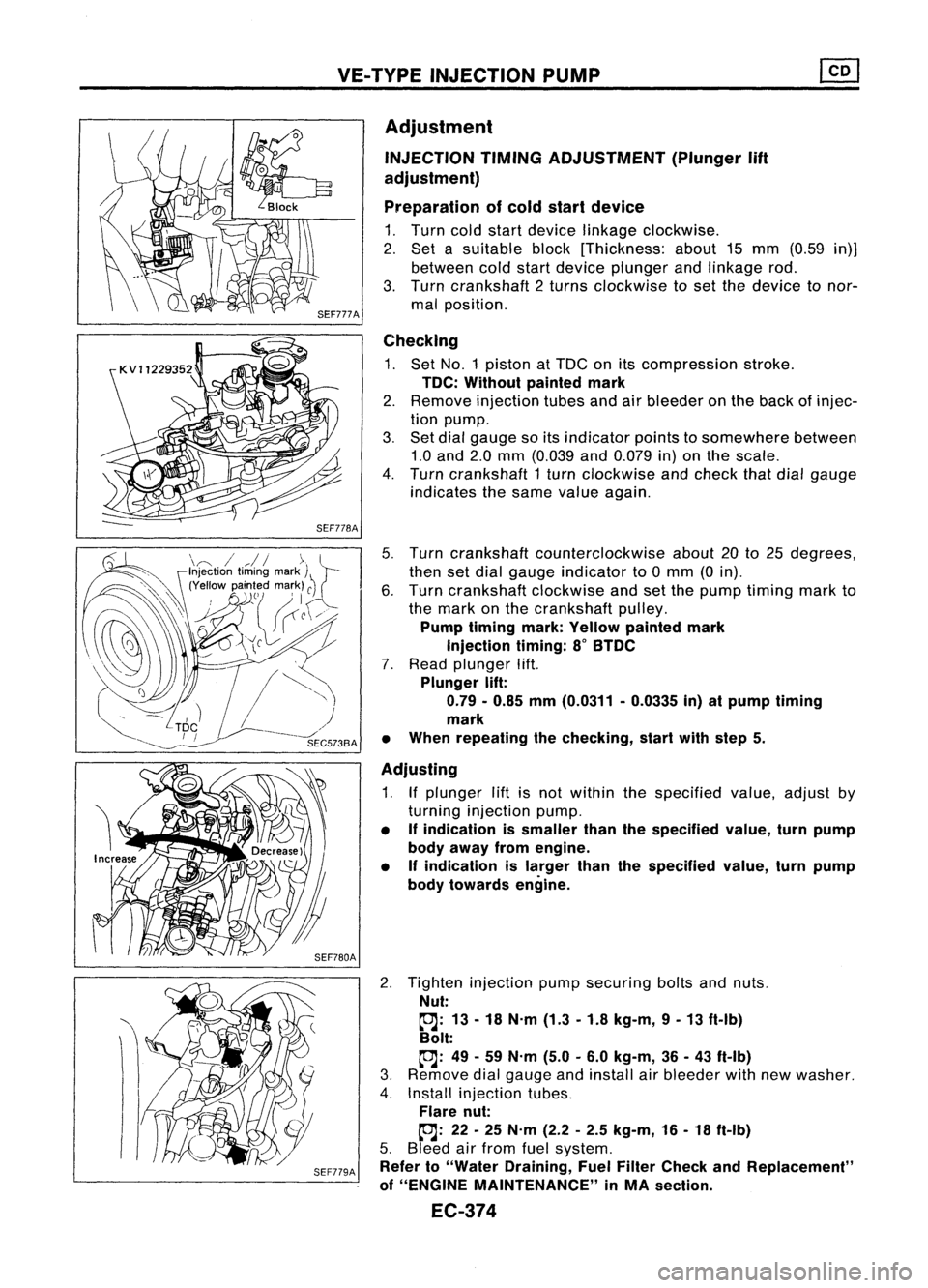
VE-TYPE INJECTION PUMP
SEF779A
Adjustment
INJECTION TIMINGADJUSTMENT (Plunger
lift
adjustment)
Preparation ofcold start device
1. Turn coldstart device linkage clockwise.
2. Set asuitable block[Thickness: about15mm (0.59 in)]
between coldstart device plunger andlinkage rod.
3. Turn crankshaft 2turns clockwise toset the device tonor-
mal position.
Checking
1. Set NO.1 piston atTDC onitscompression stroke.
TDC: Without paintedmark
2. Remove injection tubesandairbleeder onthe back ofinjec-
tion pump.
3. Set dial gauge soitsindicator pointstosomewhere between
1.0 and 2.0mm (0.039 and0.079 in)onthe scale.
4. Turn crankshaft 1turn clockwise andcheck thatdialgauge
indicates thesame value again.
5. Turn crankshaft counterclockwise about20to25 degrees,
then setdial gauge indicator to0mm (0in).
6. Turn crankshaft clockwiseandsetthe pump timing markto
the mark onthe crankshaft pulley.
Pump timing mark:Yellow painted mark
Injection timing:8
0
BTDC
7. Read plunger lift.
Plunger lift:
0.79 -0.85 mm(0.0311 -0.0335 in)atpump timing
mark
• When repeating thechecking, startwithstep 5.
Adjusting
1. Ifplunger liftisnot within thespecified value,adjust by
turning injection pump.
• Ifindication issmaller thanthespecified value,turnpump
body away fromengine.
• Ifindication islarger thanthespecified value,turnpump
body towards engine.
2. Tighten injection pumpsecuring boltsandnuts.
Nut:
~: 13-18 N.m (1.3-1.8 kg-m, 9-13 ft-Ib)
Bolt:
~: 49-59 N.m (5.0-6.0 kg-m, 36-43 ft-Ib)
3. Remove dialgauge andinstall airbleeder withnewwasher.
4. Install injection tubes.
Flare nut:
~: 22-25 N.m (2.2-2.5 kg-m, 16-18 ft-Ib)
5. Bleed airfrom fuelsystem.
Refer to"Water Draining, FuelFilter Check andReplacement"
of "ENGINE MAINTENANCE" inMA section.
EC-374
Page 1096 of 1701
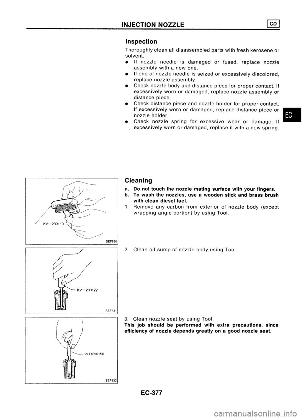
SEF830INJECTION
NOZZLE
Inspection
Thoroughly cleanalldisassembled partswithfresh kerosene or
solvent.
• Ifnozzle needle isdamaged orfused, replace nozzle
assembly withanew one.
• Ifend ofnozzle needle isseized orexcessively discolored,
replace nozzleassembly.
• Check nozzle bodyanddistance pieceforproper contact. If
excessively wornordamaged, replacenozzleassembly or
distance piece.
• Check distance pieceandnozzle holderforproper contact.
If
excessively wornordamaged, replacedistance pieceor•
nozzle holder.
• Check nozzle springforexcessive wearordamage. If
excessively wornordamaged, replaceitwith anew spring.
Cleaning
a. Donot touch thenozzle mating surface withyour fingers.
b. Towash thenozzles, useawooden stickandbrass brush
with clean diesel fuel.
1. Remove anycarbon fromexterior ofnozzle body(except
wrapping angleportion) byusing Tool.
2. Clean oilsump ofnozzle bodyusing Tool.
KV11290150 SEF831
SEF832
3.
Clean nozzle seatbyusing Tool.
This jobshould beperformed withextra precautions, since
efficiency ofnozzle depends greatlyonagood nozzle seat.
EC-377
Page 1097 of 1701
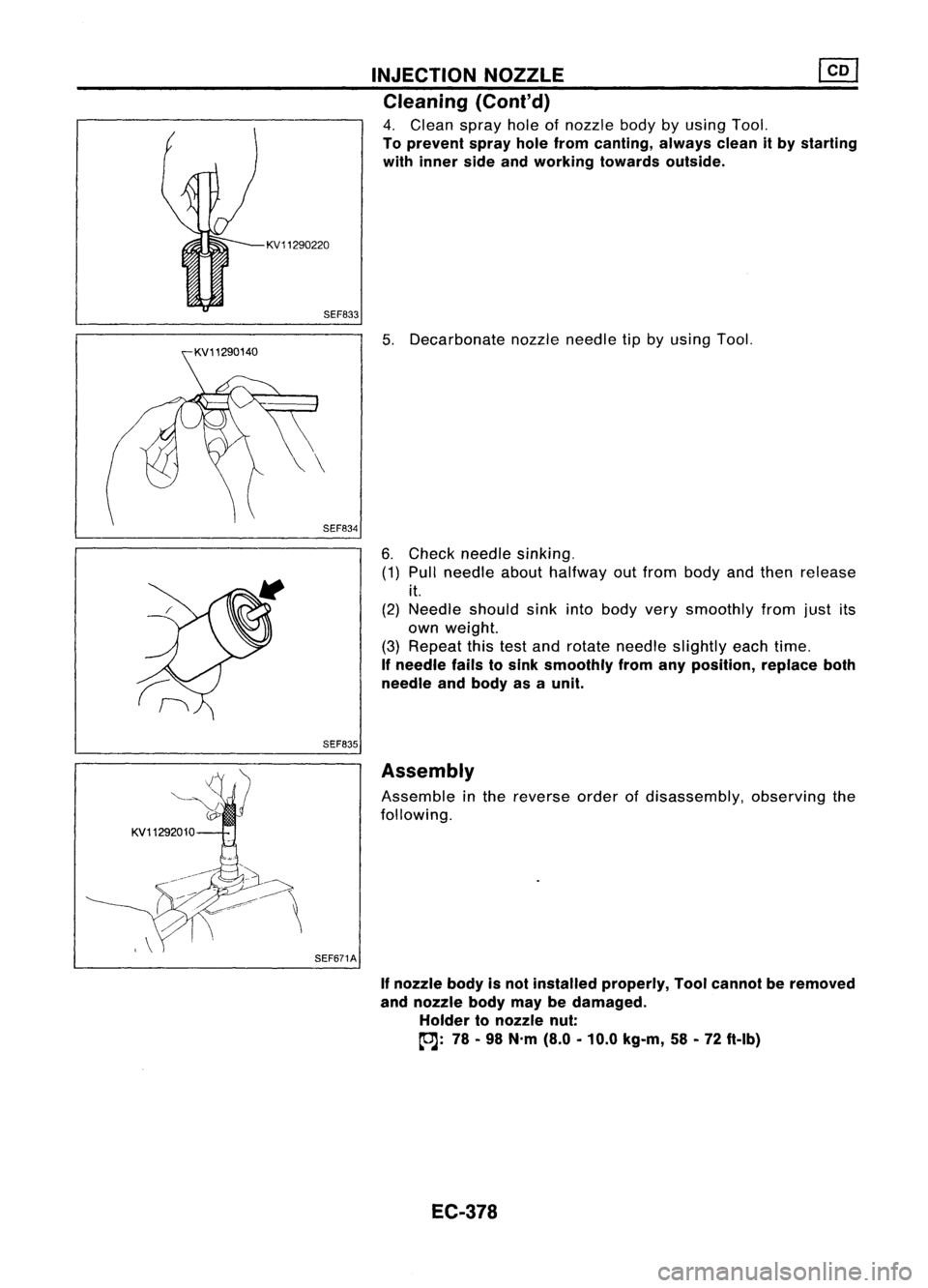
KV11290220SEF833
SEF834
SEF835 INJECTION
NOZZLE ~
Cleaning (Coni'd)
4. Clean sprayholeofnozzle bodybyusing Tool.
To prevent sprayholefrom canting, alwayscleanitby starting
with inner sideandworking towardsoutside.
5. Decarbonate nozzleneedle tipbyusing Tool.
6. Check needle sinking.
(1) Pull needle abouthalfway outfrom body andthen release
it.
(2) Needle shouldsinkintobody verysmoothly fromjustits
own weight.
(3) Repeat thistestand rotate needle slightly eachtime.
If
needle failstosink smoothly fromanyposition, replaceboth
needle andbody asaunit.
KV11292010 SEF671AAssembly
Assemble inthe reverse orderofdisassembly, observingthe
following.
If
nozzle bodyisnot installed properly, Toolcannot beremoved
and nozzle bodymaybedamaged.
Holder tonozzle nut:
(OJ:
78-98 N'm (8.0-10.0 kg-m, 58-72 ft-Ib)
EC-378
Page 1148 of 1701

ENGINECOOLING SYSTEM
Water HoseDrawing
GA14DE andGA16DE withoutVTC
GA 16DE withVTCexcept forAustralia GA15DE
MLC084A
CD
Intake manifold tothermostat
housing-1
@
Intake manifold tothermostat
housing-2
@
Radiator lowerhosetowater
inlet
@
Intake manifold tothrottle body
LC-10
@
Throttle bodytothermostat
housing
Page 1149 of 1701

ENGINECOOLING SYSTEM
Water HoseDrawing (Cont'd)
GA16DE withVTCforAustralia
Intakemanifold
5
9
•
Q)
Intake manifold toThermostat
housing (upper)
@
Intake manifold toThermostat
housing (lower)
@
Water jacket toWater pipe
lower
@
Water pipelower
CID
Water pipelower toThrottle
body
@
Water pipelower toIntake
manifold
(J)
Water pipeupper
LC-11 @
Throttle bodytoWater pipe
upper
@
Intake manifold toWater pipe
upper
@
Water pipeupper toThermostat
housing
SLC021BA