115 NISSAN ALMERA N15 1995 Service Manual
[x] Cancel search | Manufacturer: NISSAN, Model Year: 1995, Model line: ALMERA N15, Model: NISSAN ALMERA N15 1995Pages: 1701, PDF Size: 82.27 MB
Page 5 of 1701
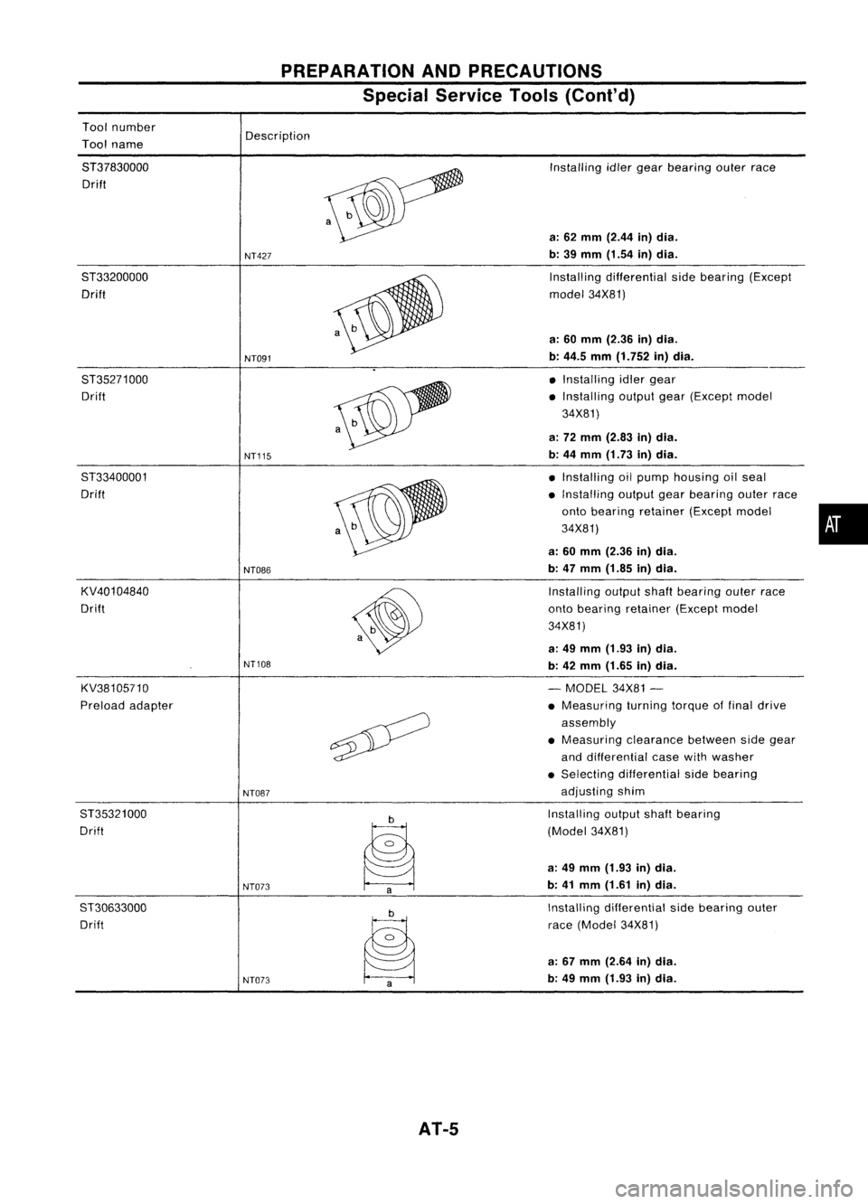
Toolnumber
Tool name
PREPARATION
ANDPRECAUTIONS
Special Service Tools(Cont'd)
Description
8T37830000 Drift
8T33200000 Drift
8T35271000 Drift
8T33400001
Drift
KV40104840
Drift
KV38105710
Preload adapter
8T35321000
Drift
ST30633000 Drift
NT427
NT091
NT115
NT086
NT108
NT087
NT073 NT073
AT-5
Installing
idlergear bearing outerrace
a: 62 mm (2.44 in)dia.
b: 39 mm (1.54 in)dia.
Installing differential sidebearing (Except
model 34X81)
a: 60 mm (2.36 in)dia.
b: 44.5 mm(1.752 in)dia.
• Installing idlergear
• Installing outputgear(Except model
34X81)
a: 72 mm (2.83 in)dia.
b: 44 mm (1.73 in)dia.
• Installing oilpump housing oilseal
• Installing outputgearbearing outerrace
onto bearing retainer (Exceptmodel •
34X81)
a: 60 mm (2.36 in)dia.
b: 47 mm (1.85 in)dia.
Installing outputshaftbearing outerrace
onto bearing retainer (Exceptmodel
34X81)
a: 49 mm (1.93 in)dia.
b: 42 mm (1.65 in)dia.
- MODEL 34X81-
• Measuring turningtorqueoffinal drive
assembly
• Measuring clearancebetweensidegear
and differential casewithwasher
• Selecting differential sidebearing
adjusting shim
Installing outputshaftbearing
(Model 34X81)
a: 49 mm (1.93 in)dia.
b: 41 mm (1.61 in)dia.
Installing differential sidebearing outer
race (Model 34X81)
a: 67 mm (2.64 in)dia.
b: 49 mm (1.93 in)dia.
Page 19 of 1701

TROUBLEDIAGNOSES
Road Testing (Cont'd)
SHIFT SCHEDULE
Drive thevehicle forapprox. 10minutes. Measuretheoiltem-
perature. Whentheoiltemperature becomesbetween50and
80°C (122and176°F), carryoutthis check.
VEHICLE SPEEDWHENSHIFTING GEARS
Model 34X68
Throttle posi- Vehicle
speedkm/h(MPH)
tion
0,~O
2
O
2
->
0
3
0
3
->
0
4
0
4
~
0
3
0
3
->
O
2
O
2
->
0,
1
2
~
1,
Full throttle
48
-56 88
-96 133
-141
80-88 37-45 45-53
(30 -35) (55-60)
-
(83-88)
(50-55) (23-28) (28
-33)
Half throttle
31
-39 54
-62 102-110
75-83 44
-52
7-15 45
-53
(19 -24) (34
-39)
(63-68) (47
-52)
(27-32) (4
-9)
(28-33)
Model 34X69and34X70
Throttle pas
i-
Vehicle
speedkm/h(MPH)
tion
0,~O
2
O
2~
0
3
0
3
->
0
4
0
4~
0
3
0
3
->
O
2
O
2~
0,
1
2~
1,
Full throttle
51
-60 94
-102 136-144
85-93 40
-48
48-56
(32 -37) (58-63)
-
(85-89)
(53-58) (25
-30) (30-35)
Half throttle
30
-38 52
-60 97-105 67-75 42-50 8-16
48-56
(19 -24) (32-37) (60-65) (42-47) (26-31) (5-10) (30-35)
Model 34X80
Throttle posi- Vehicle
speedkm/h(MPH)
tion
0,~O
2
O
2
->
0
3
0
3~
0
4
0
4
->
0
3
0
3
~
O
2
O
2
->
0,
1"
->
1,
Full throttle
52
-60 100-108 145
-153
90-98 40
-48 49-57
(32 -37) (62-67)
-
(90-95) (56-61) (25-30) (30
-35)
Half throttle
30
-38 53-61 103
-111
69-77 42
-50 8-16 49-57
(19 -24) (33-38) (64-69) (43-48) (26-31) (5-10) (30-35)
Model 34X81
Throttle posi- Vehicle
speedkm/h(MPH)
tion
0,~O
2
O
2
->
0
3
0
3
~
0
4
0
4
->
0
3
0
3
->
O
2
O
2
~
0,
1
2~
1,
Full throttle
58
-66 107
-115 160
-168
96-104 39
-47 48-56
(36 -41) (66
-71)
-
(99-104) (60-65) (24
-29) (30
-35)
33 -41 57-65 105
-113 69-77 45-53 8-16 48-56
Half throttle
(21-25) (35-40)
(65-70) (43
-48) (28-33) (5-10) (30
-35)
AT-19
•
Page 29 of 1701
•
(b):
LHDmodels
:
RHOmodels
@:
Except forEurope
and Israel
~: GAengine forAustralia
@:
Except@
*1 ...
@
30
@
115
,
ECM
(ECCS
CONTROL
MODULE)
em
_ INHIBITOR
P .. ..1P ..
-1
SWITCH
R N-0 2 R
~-o
2
@g)
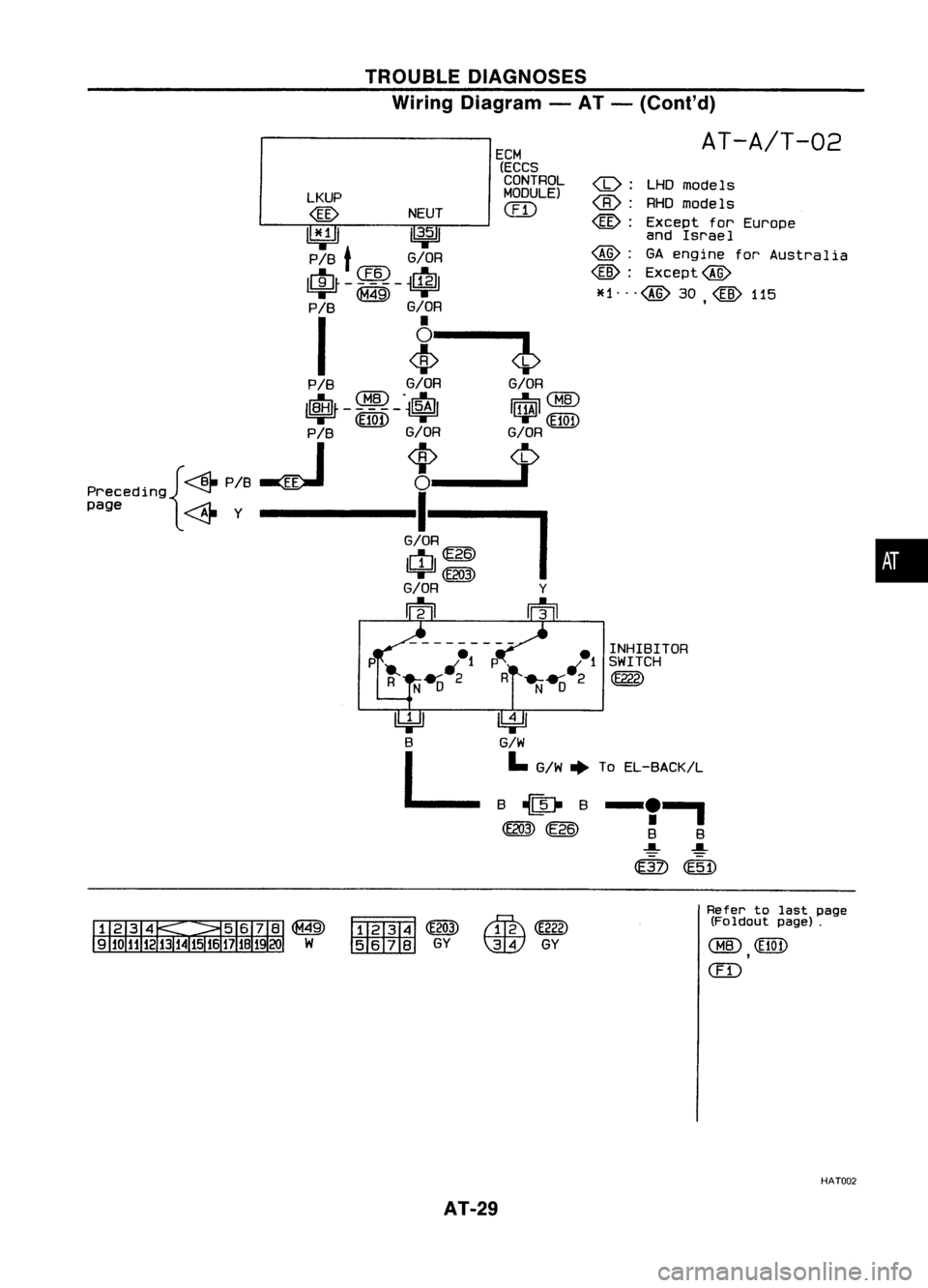
TROUBLE
DIAGNOSES
Wiring Diagram -AT -(Coni' d)
AT-A/T-02
LKUP
@
NEUT
I1¥Jl
11
3•5
1
P/B
t
G/OR
~CIID~
~-
I
i
P /B G/OR G/OR
~ CHID.
dI:-. ~
CHID
ll\tlJr -
$100 -~
I~I
P/B G/OR G/OR
. {~P/8~
*_1>
Precedlng ~
I
page ~Y-------G/O~
IUJI~
=w=
(E203)
G/OR Y
m rn
l!4='J
B
L
~
G/W
I.
G/W ~ToEL-BACK/L
-'I
B B
~ ~
@)
@j)
~
~ GY
~
(E222)
\IDY
GY Refer
tolast page
(Foldout page).
CHID
(EI0t)
,
(ill
HAT002
AT-29
Page 79 of 1701
REPAIRFORCOMPONENT PARTS
Control ValveAssembly (Cont'd)
INSPECTION
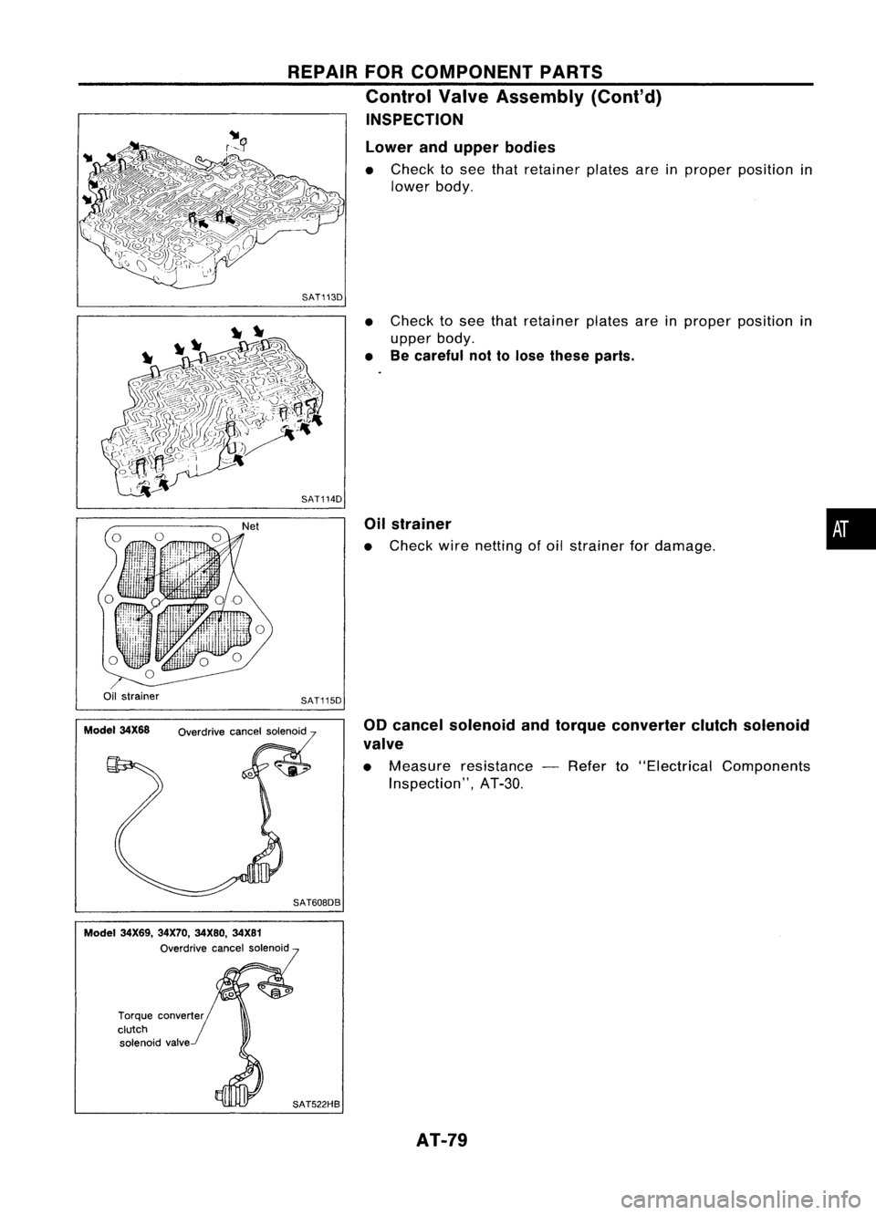
Lower andupper bodies
• Check tosee that retainer platesareinproper position in
lower body.
SAT113D
•Check tosee that retainer platesareinproper position in
upper body.
• Becareful nottolose these parts.
Oil strainer
• Check wirenetting ofoil strainer fordamage.
•
Oil strainer
Model 34X68 SAT115D
Overdrive cancelsolenoid
SAT608DB 00
cancel solenoid andtorque converter clutchsolenoid
valve
• Measure resistance -Refer to"Electrical Components
Inspection", AT-3D.
Model 34X69, 34X70,34X80, 34X81
Overdrive cancelsolenoid
Torque converter
clutch solenoid valve
SAT522HBAT-79
Page 115 of 1701
Rearinternal
gear
•
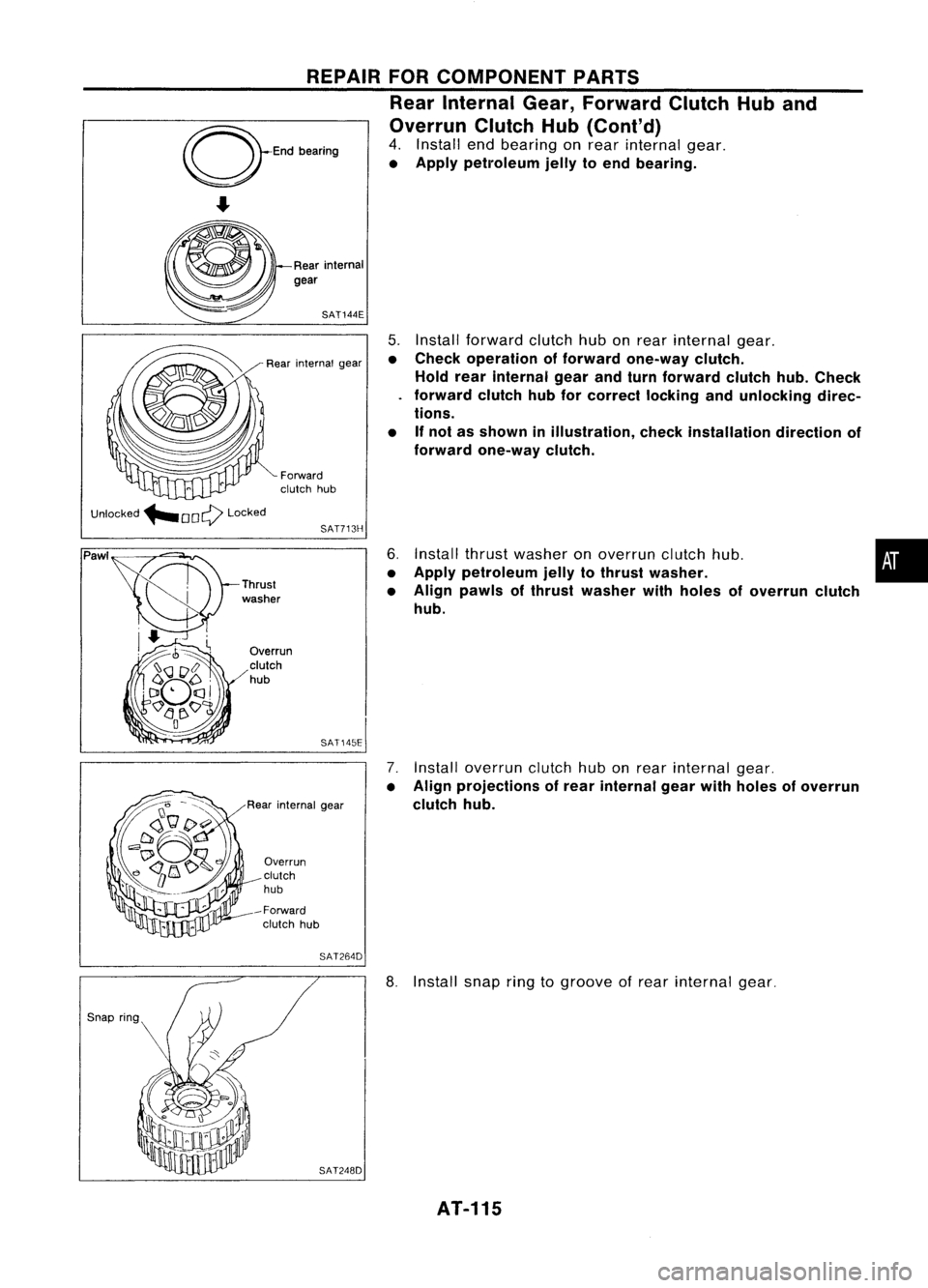
5.
Install forward clutchhubonrear internal gear.
• Check operation offorward one-way clutch.
Hold rearinternal gearandturn forward clutchhub.Check
forward clutchhubforcorrect lockingandunlocking direc-
tions.
• Ifnot asshown inillustration, checkinstallation directionof
forward one-way clutch.
6. Install thrustwasher onoverrun clutchhub.
• Apply petroleum jellytothrust washer.
• Align pawls ofthrust washer withholes ofoverrun clutch
hub.
7. Install overrun clutchhubonrear internal gear.
• Align projections ofrear internal gearwithholes ofoverrun
clutch hub.
SAT144E
REPAIR
FORCOMPONENT PARTS
Rear Internal Gear,Forward ClutchHuband
Overrun ClutchHub(Cont'd)
4. Install endbearing onrear internal gear.
• Apply petroleum jellytoend bearing.
SAT713H
Forward
clutch hub
Rear
internal gear
SAT145E
Overrun
clutch
hub
-Forward clutch hub
Overrun
clutch
hub
Rear internal gear
Unlocked
"'OOQ Locked
Pawl
SAT264D
SAT248D
8.
Install snapringtogroove ofrear internal gear.
AT-115
Page 165 of 1701
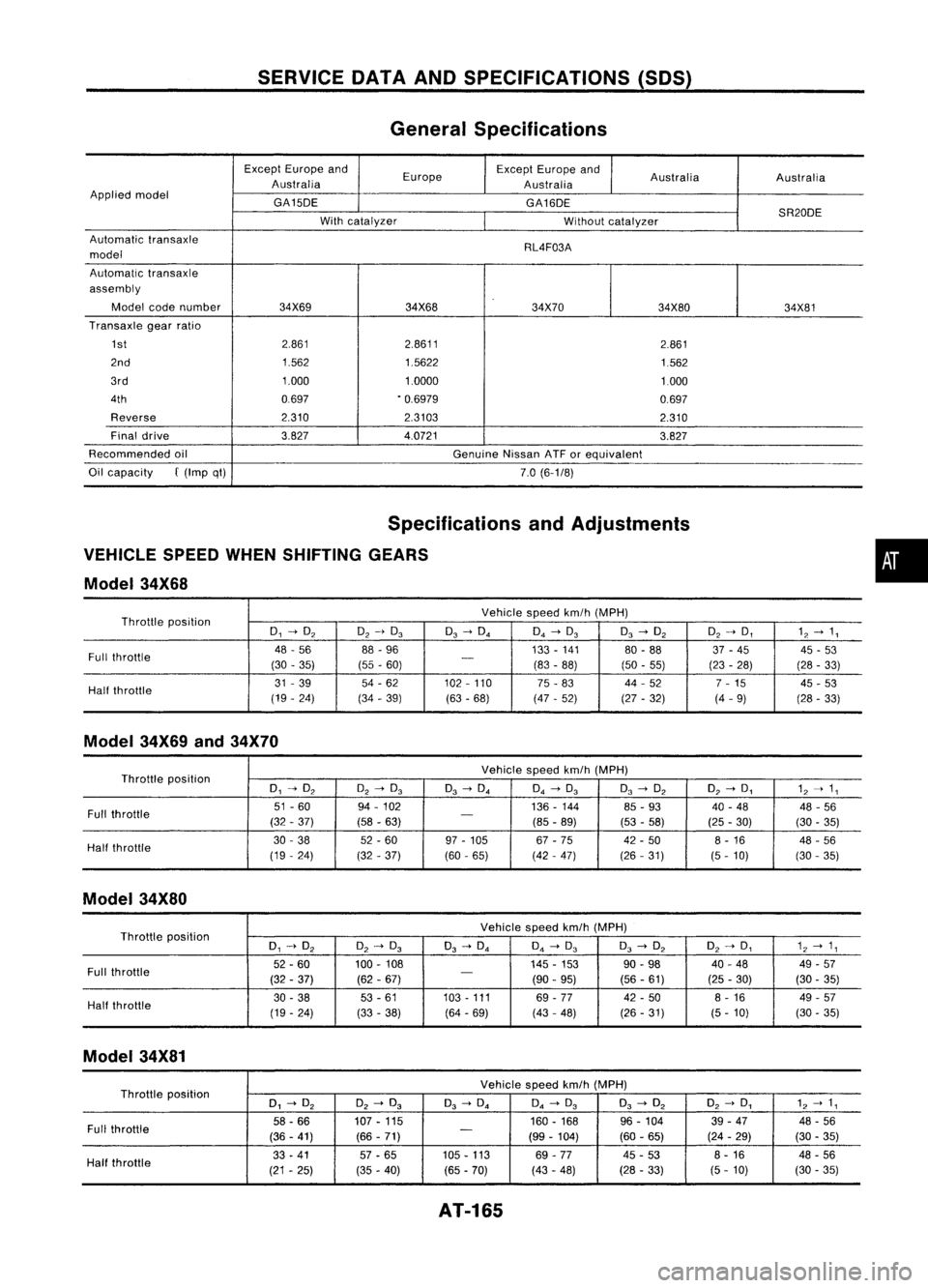
SERVICEOATAAND SPECIFICATIONS (SOS)
General Specifications
Except Europe and
Europe Except
Europe and
Australia Australia
Australia Australia
Applied model
GA150E GA160E
SR200E
With catalyzer
Withoutcatalyzer
Automatic transaxle
RL4F03A
model
Automatic transaxle
assembly
Model codenumber 34X69 34X68 34X70
34X8034X81
Transaxle gearratio
1st 2.861
2.8611
2.861
2nd 1.5621.5622
1.562
3rd 1.0001.0000
1.000
4th 0697.0.6979
0.697
Reverse 2.3102.3103
2.310
Final drive 3.8274.0721
3.827
Recommended oil
GenuineNissanATForequivalent
Oil capacity
f
(Imp qt)
7.0(6-1/8)
Specifications andAdjustments
VEHICLE SPEEDWHENSHIFTING GEARS
Model 34X68
Throttle position Vehicle
speedkm/h(MPH)
0, -->O
2
O
2
-->0
3
0
3
-->O. O.-->0
3
0
3
-->O
2
O2-->D, 12--> 1,
Full throttle 48
-56 88-96 133-141 80-88 37-45 45-53
(30 -35) (55-60)
-
(83-88) (50-55) (23-28)
(28-33)
Half throttle 31
-39 54-62 102-110
75-83 44
-52
7-15 45-53
(19 -24) (34-39) (63-68) (47-52) (27-32) (4-9)
(28-33)
Model 34X69and34X70
Throttle position Vehicle
speedkm/h(MPH)
0, -->O
2
O
2
-->0
3
0
3
-->O. O.-->0
3
0
3
-->O
2
O
2
-->0, 1
2
--> 1,
Full throttle 51
-60
94-102 136-144 85-93 40-48 48-56
(32 -37) (58-63)
-
(85-89) (53-58) (25-30)
(30-35)
Half throttle 30
-38 52-60 97-105 67-75 42-50 8-16 48-56
(19 -24)
(32-37) (60
-65) (42-47) (26-31)
(5-10) (30
-35)
Model 34X80
Throttle position Vehicle
speedkm/h(MPH)
0, -->O
2
O
2
-->0
3
0
3
-->O. O.-->0
3
0
3
-->O
2
O2-->0, 1
2
--> 1,
Full throttle 52.60
100-108 145-153 90.98
40-48 49-57
(32 -37) (62-67)
-
(90-95) (56
-61) (25-30) (30-35)
Half throttle 30
-38 53
-61 103-111
69-77 42
-50 8-16 49-57
(19 -24)
(33-38) (64-69) (43
-48) (26-31) (5-10) (30-35)
Model 34X81
Throttle position Vehicle
speedkm/h(MPH)
0, -->O
2
O
2
-->0
3
0
3
-->O.
O.
-->0
3
0
3
-->O
2
O
2
-->0, 1
2
--> 1,
Full throttle 58.66
107.115 160.168
96-104 39-47 48-56
(36 -41) (66-71)
-
(99-104) (60-65) (24-29) (30-35)
Half throttle 33
-41 57-65 105.113
69-77 45
-53 8.
16
48-56
(21 -25) (35-40) (65.70)
(43-48) (28
-33)
(5-10) (30
-35)
AT-165
•
Page 167 of 1701
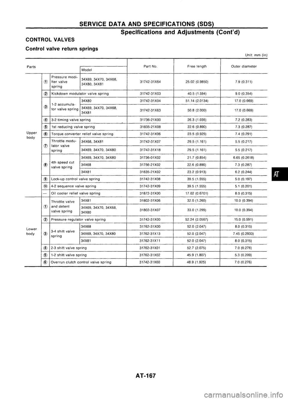
SERVICEDATAANDSPECIFICATIONS (SOS)
Specifications andAdjustments (Cont'd)
CONTROL VALVES
Control valvereturn springs
Unit:
mm
(in)
Parts Part
No. Freelength
Outerdiameter
Model
Pressure modi-
34X69,34X70, 34X68,
d)
liervalve 31742-31X642502(0.9850) 79(0.311)
spring 34X80,
34X81
@)
Kickdown
modulator valvespring 31742-31X03 40.5(1.594) 9.0(0.354)
34X80 31742-31X0451.14(2.0134) 17.0(0.669)
@
1-2
accumula-
tor valve spring 34X69,
34X70,34X68,
34X81 31742-31X63
50.8(2000) 17.0(0.669)
@
3-2timing valvespring 31736-21
XOO 26.3(1.035) 7.2(0.283)
~ 1st
reducing valvespring 31835-21X0822.6(0.890) 7.3(0.287)
Upper
@
Torque converter reliefvalve spring 31742-31X06 23.5(0.925) 7.4(0.291)
body Throttlemodu-
34X68,34X81
31742-31X07 29.5
(1.161)
5.5(0.217)
(J)
lator valve
spring 34X69,
34X70, 34X80 31742-31X18 29.5(1161)
5.5(0.217)
34X69, 34X70, 34X80 31736-01X02 21.7(0.854) 6.65(0.2618)
@
4th
speed cut
34X68 31756-21X0222.6(0.890)
7.3(0.287)
valve spring
34X81 31835-21X0223.2(0913) 6.2(0.244)
@
Lock-up
controlvalvespring 31742-31X08
39.5(1.555) 50(0.197)
@
4-2sequence valvespring 31742-31X0939.5(1.555) 51(0.201)
-
Oilcooler reliefvalve spring 31872-31XOO17.02(0.6701) 8.0(0.315)
Throttle valve 34X81
31802-31X06 32.0(1.260) 10.0(0.394)
d)
anddetent
34X69,34X70, 34X68,
valve spring
34X80 31802-31X07
33.0
(1.299)
10.0(0.394)
(2)
Pressure regulatorvalvespring 31742-31XOO 5224(2.0567) 15.0(0.591)
Lower 34X68
31762-31XOO
52.0(2.047)
8.0(0.315)
body
@
3-4
shift valve
34X69,34X70,34X80 31762-31X13 52.0(2.047) 7.45(0.2933)
spring
34X81 31762-31X1152.0(2.047) 80(0.315)
@
2-3shift valve spring 31762-31X0152.7(2.075) 7.0(0.276)
cID
1-2
shift valve spring 31762-31X0245.9(1.807) 5.3(0.209)
@
Overrun clutchcontrol valvespring 31742-31X60 48.9
(1.925) 7.0(0.276)
AT-167
•
Page 170 of 1701
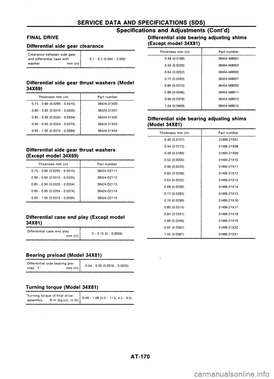
Differential sidegear clearance
FINAL
DRIVE SERVICE
DATAANDSPECIFICATIONS (SOS)
Specifications andAdjustments (Cont'd)
Differential sidebearing adjusting shims
(Except model34X81)
Differential sidegear thrust washers
(Except model34X69)
Differential caseendplay (Except model
34X81) Differential
sidegear thrust washers (Model
34X69)
Clearance
betweensidegear
and differential easewith
washer mm(in)
Thickness mm(in)
0.75 -0.80 (0.0295 -0.0315)
0.80 -0.85 (0.0315 -0.0335)
0.85 -0.90 (0.0335 -0.0354)
0.90 -0.95 (0.0354 -0.0374)
0.95 -1.00 (0.0374 -0.0394)
Thickness mm(in)
0.75 -0.80 (0.0295 -0.0315)
0.80 -0.85 (0.0315 -0.0335)
0.85 -090 (0.0335 -0.0354)
090 -0.95 (0.0354 -0.0374)
0.95 -1.00 (0.0374 -0.0394)
Differential caseendplay
mm (in)
0.1
-0.2 (0.004 -0.008)
Part number
38424-31 XOO
38424-31X01
38424-31 X02
38424-31 X03
38424-31X04
Part number
38424-02111
38424-02112
38424-02113
38424-02114 38424-02115
0-015 (0-0.0059)
Thickness
mm(in) Part
number
0.48 (0.0189) 38454-M8001
0.56 (0.0220) 38454-M8003
0.64 (0.0252) 38454-M8005
0.72 (0.0283) 38454-M8007
0.80 (0.0315) 38454-M8009
0.88 (0.0346) 38454-M8011
0.96 (0.0378) 38454-M8013
1.04 (0.0409) 38454-M8015
Differential sidebearing adjusting shims
(Model 34X81)
Thickness mm(in) Partnumber
0.40 (0.0157) 31499-21X07
0.44 (0.0173) 31499-21X08
0.48 (00189) 31499-21X09
0.52 (0.0205) 31499-21X10
0.56 (0.0220) 31499-21X11
0.60 (00236) 31499-21X12
0.64 (0.0252) 31499-21X13
068 (00268) 31499-21X14
0.72 (00283) 31499-21X15
076 (0.0299) 31499-21X16
0.80 (0.0315) 31499-21X17
0.84 (0.0331) 31499-21X18
0.88 (0.0346) 31499-21X19
0.92 (0.0362) 31499-21X20
1.44 (00567) 31499-21X21
Bearing preload(Model34X81)
Oifferential sidebearing pre-
load
'T'
mm(in)
004
-009 (00016 -0.0035)
Turning torque(Model 34X81)
Turning torqueoffinal drive
049_108 ( _11 4_5)
assembly Nm(kg-em, in-Ib)' .
5.0 .0,.3 9.
AT-170
Page 179 of 1701
![NISSAN ALMERA N15 1995 Service Manual ________BODYCOMPONENT PARTS _
___________ REPLACEMENTOPERATIONS
Rear Fender
5-doorhatchback
BodyComponent Parts Sedan
5-door Hatchback
~
o
o
'"C
iD
c
co
"0
(]J
en
@
1or 111
1 NISSAN ALMERA N15 1995 Service Manual ________BODYCOMPONENT PARTS _
___________ REPLACEMENTOPERATIONS
Rear Fender
5-doorhatchback
BodyComponent Parts Sedan
5-door Hatchback
~
o
o
'"C
iD
c
co
"0
(]J
en
@
1or 111
1](/img/5/57349/w960_57349-178.png)
________BODYCOMPONENT PARTS _
___________ REPLACEMENTOPERATIONS
Rear Fender
5-doorhatchback
BodyComponent Parts Sedan
5-door Hatchback
~
o
o
'"C
iD
c
co
"0
(]J
en
@
1or 111
1IIl.
(length: 10mm)
@ 4or 113
@
1or 111
@
1
or
11 1
112
111
112
M.I. Gseam weld/
Point weld
113
111
_ 7orll5
Rear pillar inner
reinforcement
_ 200r 1115
M.1. Gplug wel(d For3panels plugweld method )
· r
.A===-= .B~
116
~
c
[IJ
co
.......
"0
:I:
(]J
[J
"en
ID
1IIl.
~~f~
@90r1l7
_50r1l4_5orll4
c
""
~
_
4orll3
co
"0
(]J
en
_ 3orll2
c
co
@ 1or 111
"0
[IJ
(]J
111
.......
en
_ 12 orll 9
:I:
0
LO
@ 5orll 4
Unit:mm
2-spot welds 3-spotwelds
Service
Joint
-41-
-4-
Page 185 of 1701
REPLACEMENTOPERATIONS
Front SideMember (PartialReplacement)
(Work afterradiator coresupport hasbeen removed.) ________
CORROSIONPROTECTION _
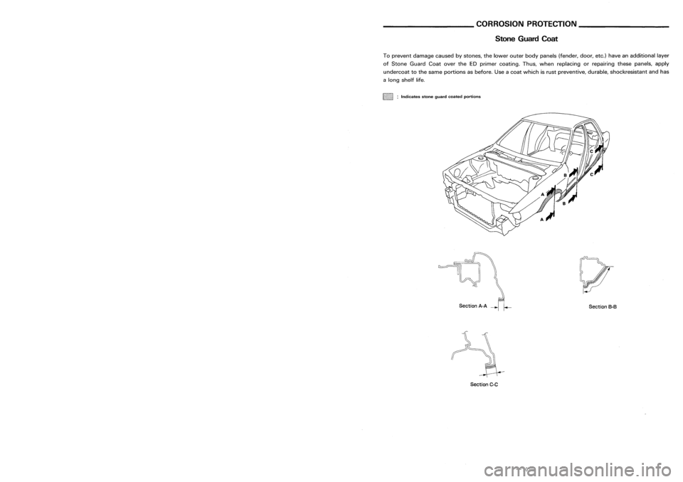
Stone Guard Coat
SectionB-B
Section
A-A
--r':":'
To
prevent damage causedbystones, thelower outerbodypanels (fender, door,etc.)have anadditional layer
of Stone Guard CoatovertheEDprimer coating. Thus,when replacing orrepairing thesepanels, apply
undercoat tothe same portions asbefore. Useacoat which isrust preventive, durable,shockresistant andhas
a long shelf life.
~mm1111i :
Indicates stoneguard coated portions
114
Patch
118
111
115
114
hoodledge
panel
117
111
Unit:mm
8
Patch
""
"
"
(Thickness: 1mm)
-\
Service
Joint
(This figure showrightfront sidemember)
2-spot welds 3-spotwelds M.1.
Gplug weld MIG seam weld/
(For 3panels plugweld method )P1ID.~irit
F
weld
• rr=
.A=-= .B~
G1J --- ~
Section
C-C
-35- -10-