ECU NISSAN ALMERA N15 1995 Service Manual
[x] Cancel search | Manufacturer: NISSAN, Model Year: 1995, Model line: ALMERA N15, Model: NISSAN ALMERA N15 1995Pages: 1701, PDF Size: 82.27 MB
Page 39 of 1701
REMOVALANDINSTALLATION
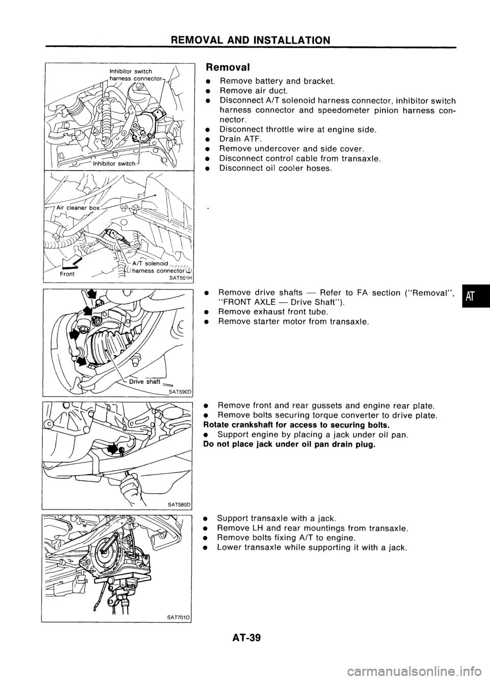
Removal
• Remove batteryandbracket.
• Remove airduct.
• Disconnect
AIT
solenoid harnessconnector, inhibitorswitch
harness connector andspeedometer pinionharness con-
nector.
• Disconnect throttlewireatengine side.
• Drain ATF.
• Remove undercover andside cover.
• Disconnect controlcablefromtransaxle.
• Disconnect oilcooler hoses.
• Remove driveshafts -Refer toFA section ("Removal", •
"FRONT AXLE-Drive Shaft").
• Remove exhaustfronttube.
• Remove startermotorfromtransaxle.
• Remove frontandrear gussets andengine rearplate.
• Remove boltssecuring torqueconverter todrive plate.
Rotate crankshaft foraccess tosecuring bolts.
• Support enginebyplacing ajack under oilpan.
Do not place jackunder oilpan drain plug.
• Support transaxle withajack.
• Remove LHand rear mountings fromtransaxle.
• Remove boltsfixing
AIT
toengine.
• Lower transaxle whilesupporting
it
with ajack.
AT-39
Page 57 of 1701
l~~
.
_~
Unit:mm(in)
SAT039D DISASSEMBLY
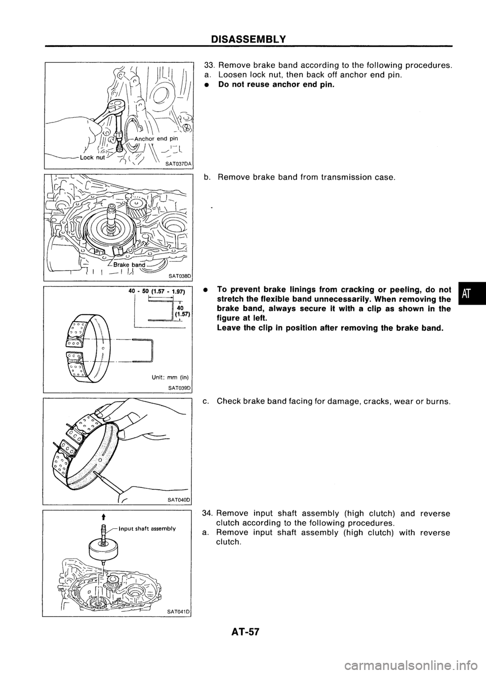
33. Remove brakebandaccording tothe following procedures.
a. Loosen locknut,then back offanchor endpin.
• Donot reuse anchor endpin.
b. Remove brakebandfromtransmission case.
• Toprevent brakelinings fromcracking orpeeling, donot •
stretch theflexible bandunnecessarily. Whenremoving the
i
brake band,always secureitwith aclip asshown inthe
figure atleft.
Leave theclip inposition afterremoving thebrake band.
c. Check brakebandfacing fordamage, cracks,wearorburns.
34. Remove inputshaftassembly (highclutch) andreverse
clutch according tothe following procedures.
a. Remove inputshaft assembly (highclutch) withreverse
clutch.
AT-57
Page 225 of 1701
BODYEND
Body Front End
• When removing orinstalling hood,placeacloth orother padding onhood. Thisprevents vehiclebody
from being scratched.
• Bumper fasciaismade ofplastic. Donot use excessive forceandbesure tokeep oilaway fromit.
• Hood adjustment: Adjustathinge portion.
• Hood lockadjustment: Afteradjusting, checkhoodlockcontrol operation. Applyacoat ofgrease to
hood locks engaging mechanism.
• Hood opener: Donot attempt tobend cable forcibly. Doingsoincreases effortrequired tounlock
hood.
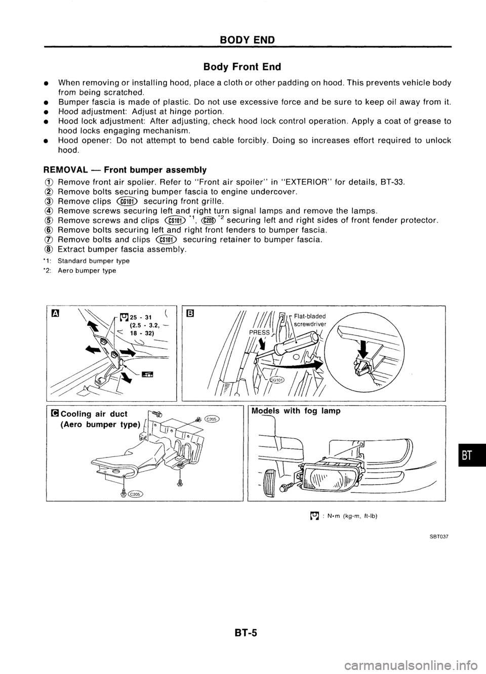
REMOVAL -Front bumper assembly
CD
Remove frontairspolier. Referto"Front
air
spoiler" in"EXTERIOR" fordetails, BT-33.
@
Remove boltssecuring bumperfasciatoengine undercover.
CID
Remove clips
@QD
securing frontgrille.
@
Remove screwssecuring leftand right turnsignal lampsandremove thelamps.
@
Remove screwsandclips
@W
*1,
@
*2
securing
leftand right sides offront fender protector.
@)
Remove boltssecuring leftand right front fenders tobumper fascia.
([) Remove boltsandclips
@W
securing retainertobumper fascia.
@)
Extract bumper fasciaassembly.
*1: Standard bumpertype
*2: Aero bumper type
to.J:
N'm (kg-m, ft-Ib)
SBT037
B1-5
•
Page 226 of 1701
BODYEND
Body Front End(Cont'd)
SEC. 261-620-623-650-656
Bumperfasciaassembly
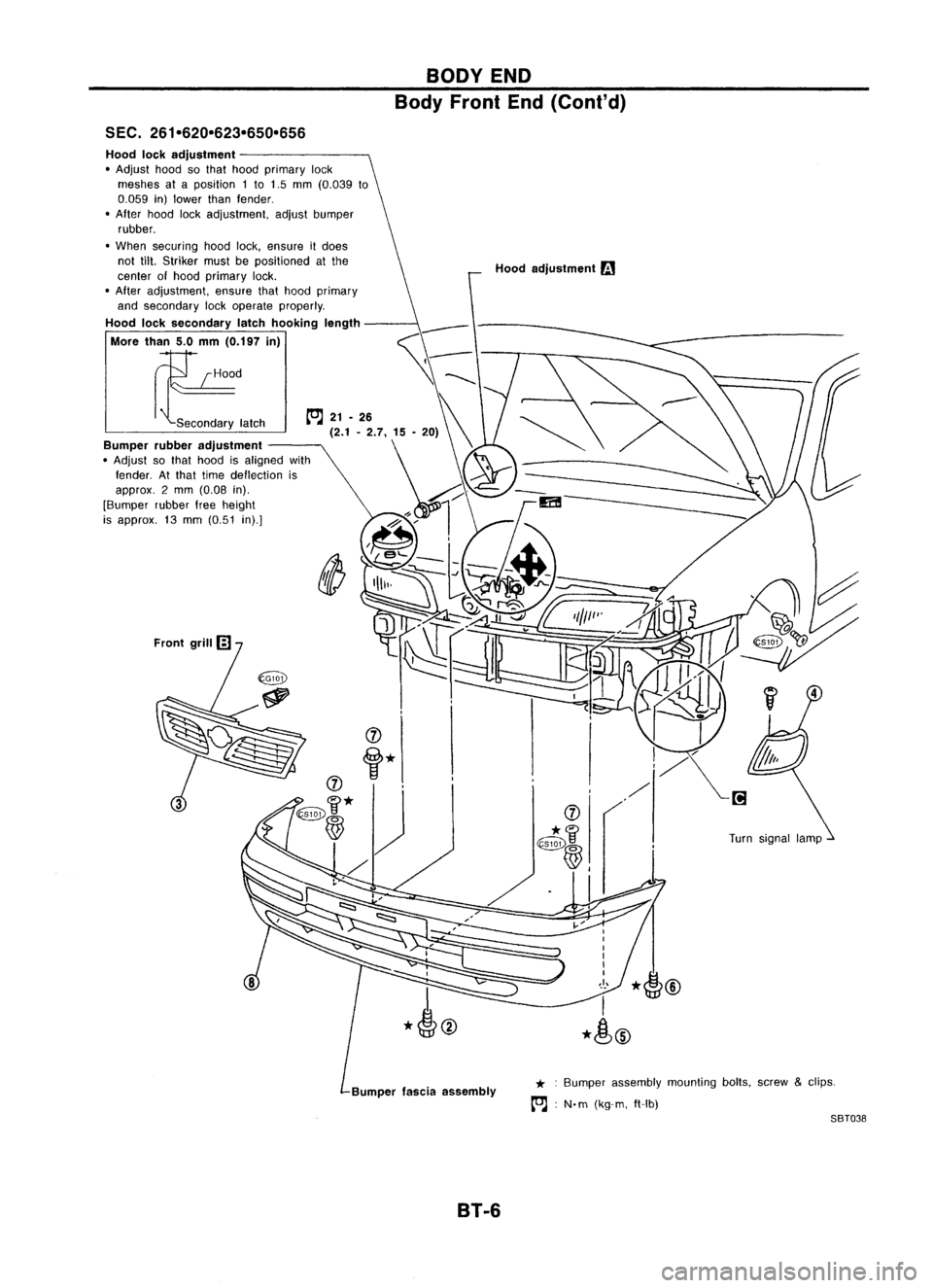
Hood
lockadjustment
• Adjust hoodsothat hood primary lock
meshes ataposition 1to 1.5 mm (0.039 to
0.059 in)lower thanfender .
• After hoodlockadjustment, adjustbumper
rubber.
• When securing hoodlock,ensure itdoes
not tilt.Striker mustbepositioned atthe
center ofhood primary lock.
• After adjustment, ensurethathood primary
and secondary lockoperate properly.
Hood locksecondary latchhooking length
More than5.0mm (0.197 in)
E
Secondary latch Hood
adjustment
r.:.1
* :Bumper assembly mountingbolts,screw
&
clips.
[OJ :
N. m (kg-m, ft-Ib)
SBT038
B1-6
Page 227 of 1701
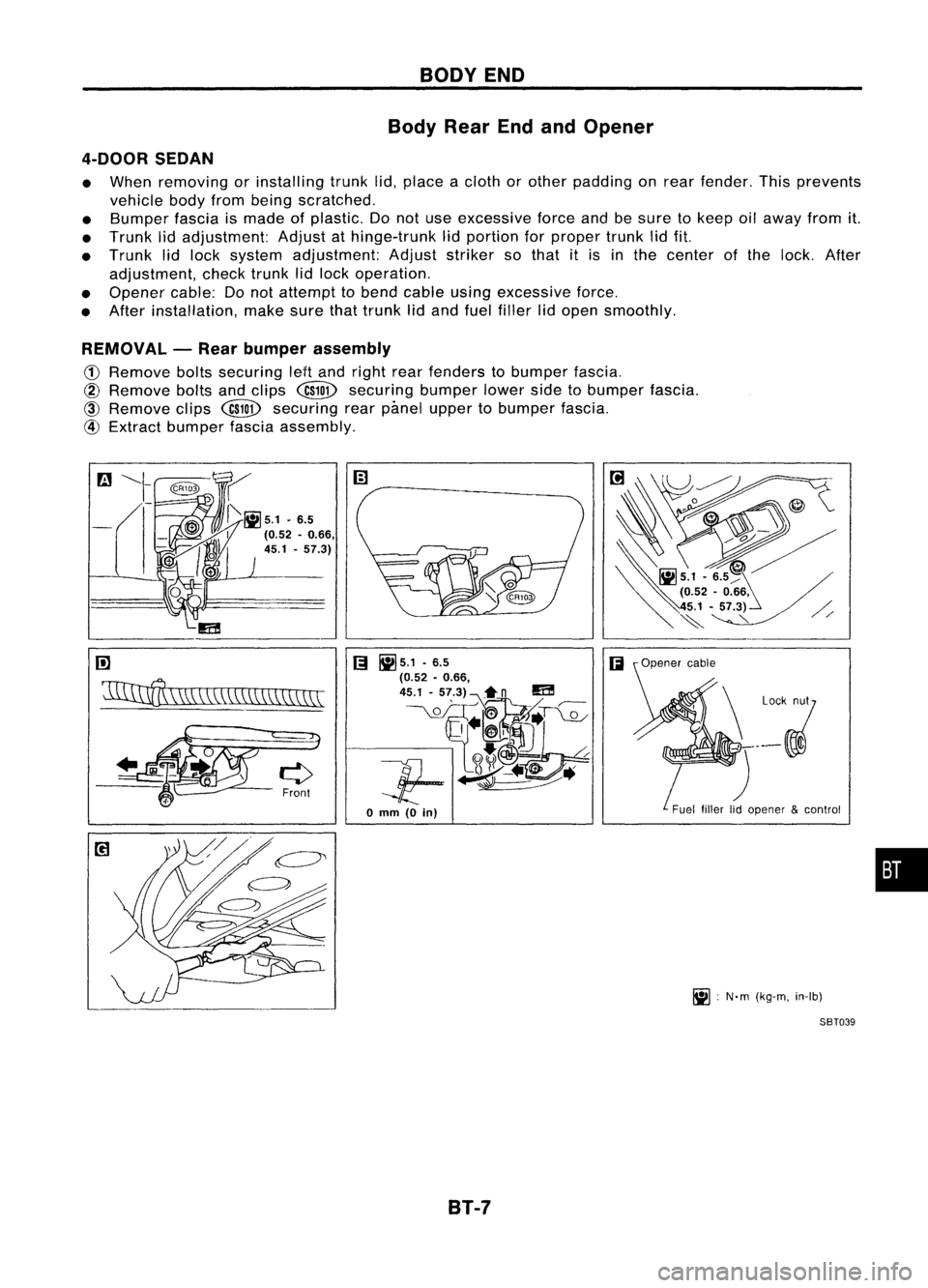
BODYEND
Body RearEndandOpener
4-DOOR SEDAN
• When removing orinstalling trunklid,place acloth orother padding onrear fender. Thisprevents
vehicle bodyfrombeing scratched.
• Bumper fasciaismade ofplastic. Donot use excessive forceandbesure tokeep oilaway fromit.
• Trunk lidadjustment: Adjustathinge-trunk lidportion forproper trunklidfit.
• Trunk lidlock system adjustment: Adjuststriker sothat itis inthe center ofthe lock. After
adjustment, checktrunklidlock operation.
• Opener cable:Donot attempt tobend cable usingexcessive force.
• After installation, makesurethattrunk lidand fuel filler lidopen smoothly.
REMOVAL -Rear bumper assembly
CD
Remove boltssecuring leHand right rearfenders tobumper fascia.
@
Remove boltsandclips
@ID
securing bumperlowersidetobumper fascia.
@
Remove clips
@ID
securing rearpimel upper tobumper fascia.
@
Extract bumper fasciaassembly.
rn
'11IInff\
\W,\\CC\\\\\\\\\\\\\\
[;I
~5.1 .6.5
(;I
(0.52 •0.66,
45.1 -57.3)~n
m
__ \.QL_OIT~~T~
Jf-~~
o
mm
(0
in)
B1-7 Fuel
fillerlidopener &control
~ :N'm (kg-m, in-Ib)
SBT039
•
Page 229 of 1701
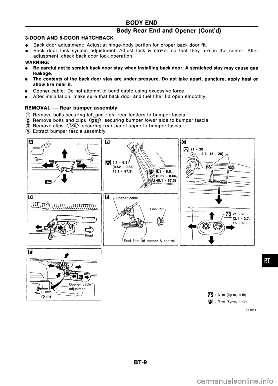
BODYEND
Body RearEndandOpener (Cont'd)
3-DOOR AND5-DOOR HATCHBACK
• Back dooradjustment: Adjustathinge-body portionforproper backdoorfit.
• Back doorlocksystem adjustment: Adjustlock
&
striker sothat they areinthe center. After
adjustment, checkbackdoor lockoperation.
WARNING:
• Becareful nottoscratch backdoor staywhen installing backdoor. Ascratched staymay cause gas
leakage.
• The contents ofthe back doorstayareunder pressure. Donot take apart, puncture, applyheator
allow firenear it.
• Opener cable:Donot attempt tobend cable usingexcessive force.
• After installation, makesurethatback doorandfuel filler lidopen smoothly.
REMOVAL -Rear bumper assembly
(1)
Remove boltssecuring leftand right rearfenders tobumper fascia.
@
Remove boltsandclips
@ill>
securi-ng bumperlowersidetobumper fascia.
@)
Remove clips~ securing rearpanel upper tobumper fascia.
@
Extract bumper fasciaassembly.
rn
~\\\\\\\\\\\\\\\\\\\\\\
I,"-
1f;
Openercable
l
'\ '--- adju~~m~nl
omm~
(0
in)
B1-9
[O.J
:
N.m (kg-m, Il-Ib)
~ :N'm (kg-m, in-Ib)
SBT041
•
Page 242 of 1701
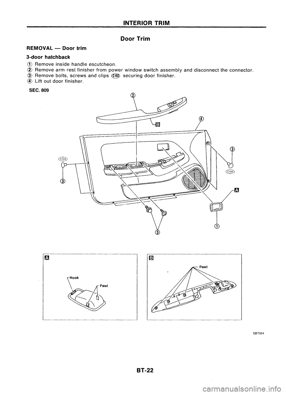
INTERIORTRIM
Door Trim
REMOVAL -Door trim
3-door hatchback
(j)
Remove insidehandle escutcheon.
@
Remove armrestfinisher frompower window switchassembly anddisconnect theconnector.
@
Remove bolts,screws andclips
@
securing doorfinisher.
@
Lift out door finisher.
SEC. 809
@
""J
r
@
a
~' SBT054
8T-22
Page 243 of 1701
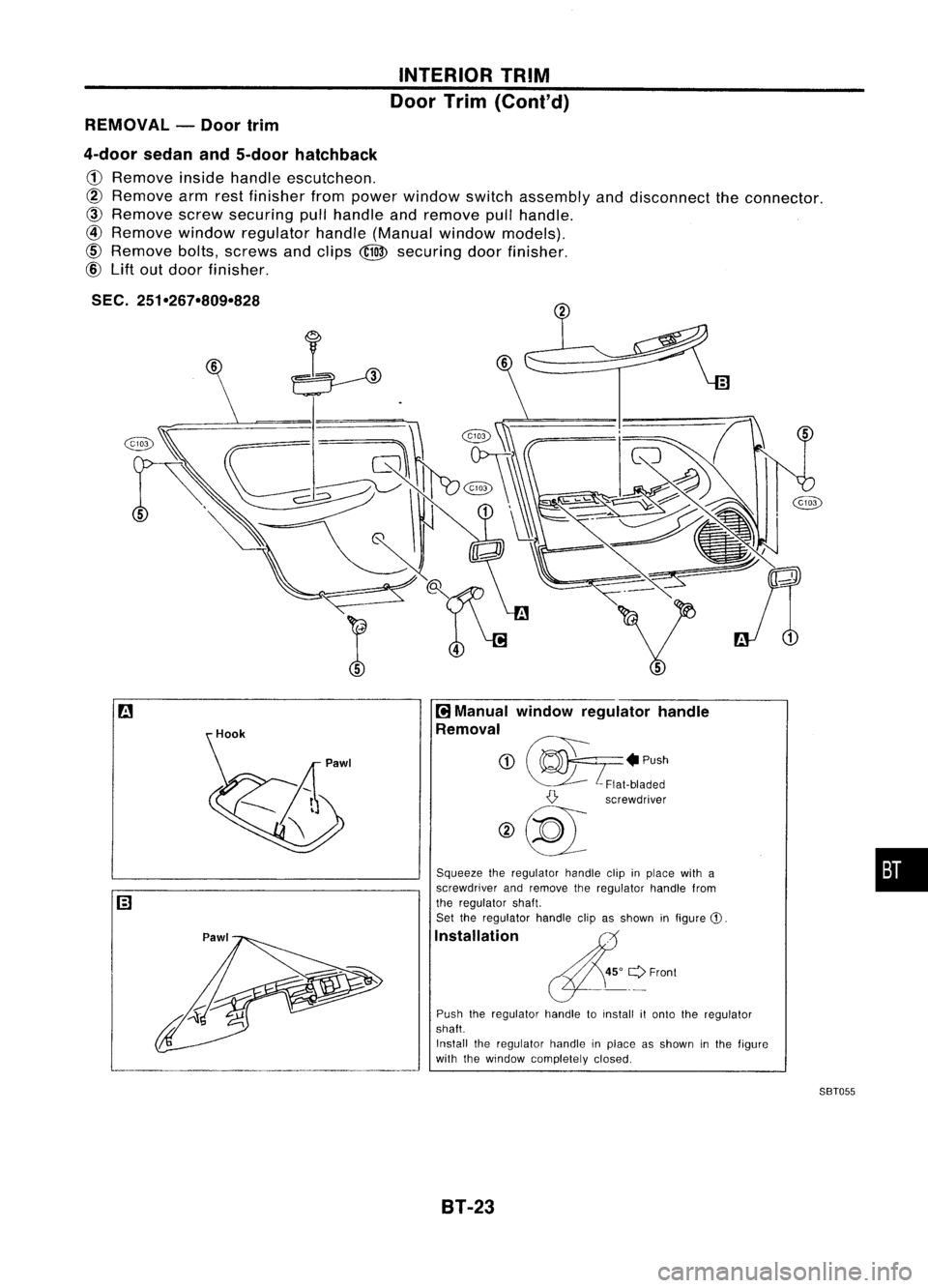
INTERIORTRIM
Door Trim
(Coni' d)
REMOVAL -Door trim
4-door sedanand5-door hatchback
G)
Remove insidehandle escutcheon.
CID
Remove armrestfinisher frompower window switchassembly anddisconnect theconnector.
@
Remove screwsecuring pullhandle andremove pullhandle.
@
Remove windowregulator handle(Manual windowmodels).
@
Remove bolts,screws andclips ~securing doorfinisher.
@ Lift outdoor finisher.
SEC. 251-267-809-828
Hook
:
~ Manual window regulator handle
Removal
(j)
~? .P"h
~ Flat-bladed
{} screwdriver
@~l
Squeeze theregulator handleclipinplace witha
screwdriver andremove theregulator handlefrom
the regulator shaft.
Set theregulator handleclipasshown infigure
CD.
Installation
Push theregulator handletoinstall itonto theregulator
shaft.
Install theregulator handleinplace asshown inthe figure
with thewindow completely closed.
8T-23
88T055
•
Page 244 of 1701
INTERIORTRIM
Roof Trim
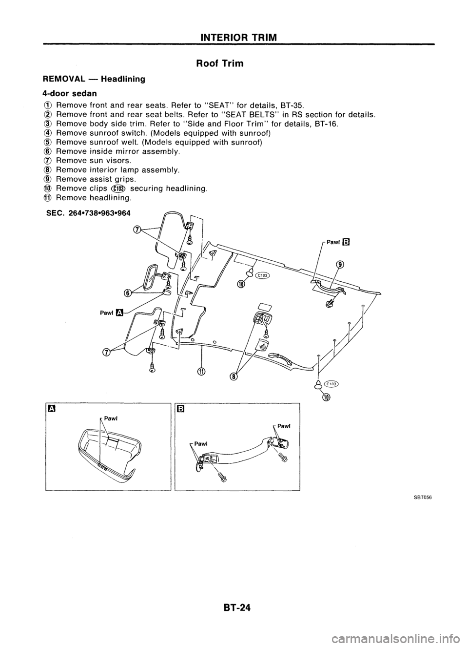
REMOVAL -Headlining
4-door sedan
CD
Remove frontandrear seats. Referto"SEAT" fordetails, BT-35.
@
Remove frontandrear seat belts. Referto"SEAT BELTS" inRS section fordetails.
@)
Remove bodysidetrim. Refer to"Side andFloor Trim" fordetails, BT-16.
@
Remove sunroofswitch.(Models equipped withsunroof)
@
Remove sunroofwelt.(Models equipped withsunroof)
@
Remove insidemirror assembly.
([) Remove sunvisors.
@
Remove interiorlampassembly.
@
Remove assistgrips.
@)
Remove clips
@
securing headlining.
@
Remove headlining.
SEC. 264-738-963-964
9
Pawl'
Pawl SBT056
BT-24
Page 245 of 1701
INTERIORTRIM
Roof Trim (Cont'd)
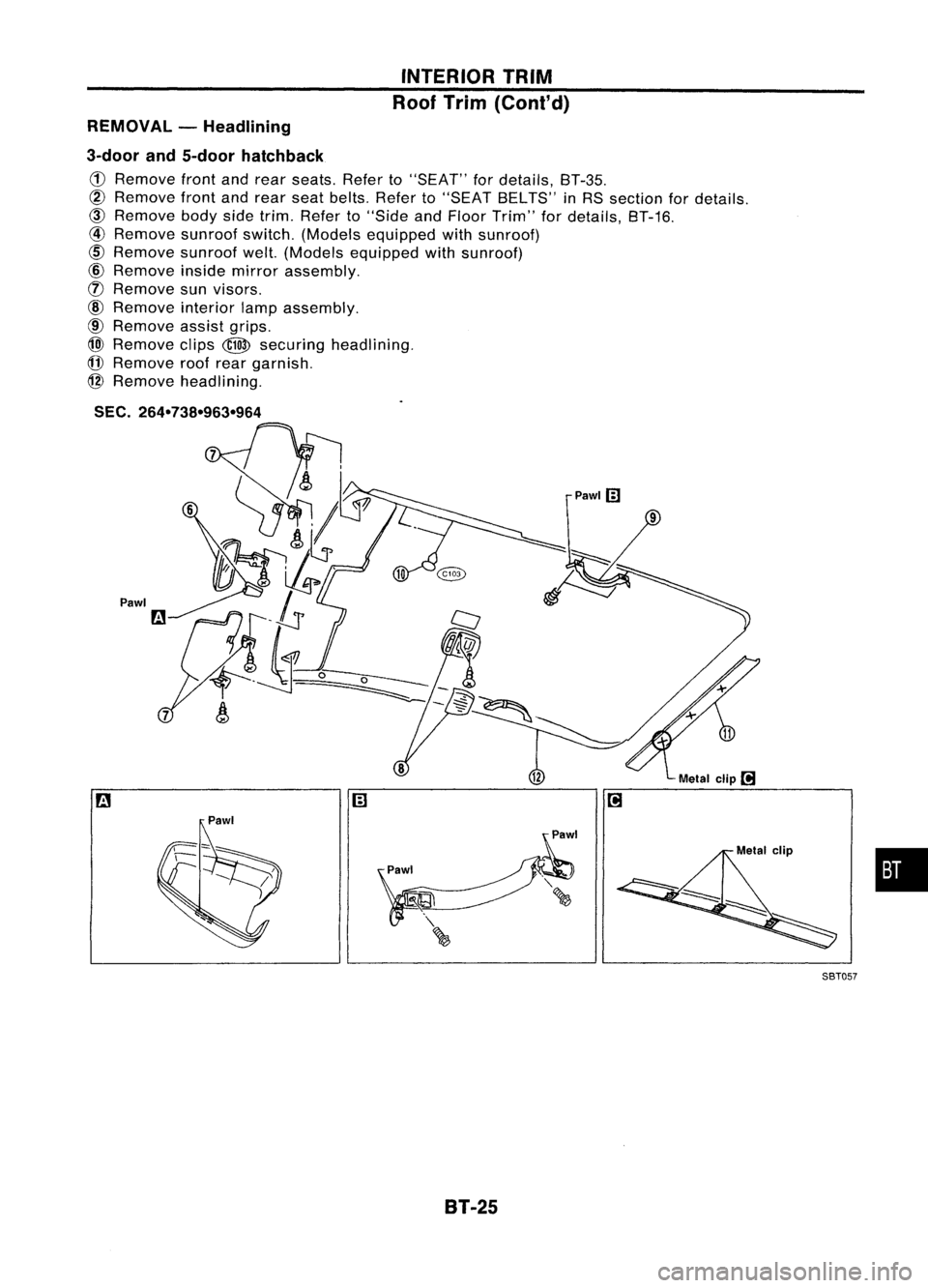
REMOVAL -Headlining
3-door and5-door hatchback
CD
Remove frontandrear seats. Referto"SEAT" fordetails, BT-35.
@
Remove frontandrear seat belts. Referto"SEAT BELTS" inRS section fordetails.
@)
Remove bodysidetrim. Refer to"Side andFloor Trim" fordetails, BT-16.
@
Remove sunroofswitch.(Models equipped withsunroof)
cID
Remove sunroofwelt.(Models equipped withsunroof)
@
Remove insidemirror assembly.
(f)
Remove sunvisors.
@
Remove interiorlampassembly.
@
Remove assistgrips.
@)
Remove clips
@
securing headlining.
(j]
Remove roofrear garnish.
@
Remove headlining.
SEC.
264-738-963-964
Pawl
•
Metal
clip
l!1
Pawlm
m
SBT05?
8T-25