air NISSAN ALMERA N15 1995 Service Manual
[x] Cancel search | Manufacturer: NISSAN, Model Year: 1995, Model line: ALMERA N15, Model: NISSAN ALMERA N15 1995Pages: 1701, PDF Size: 82.27 MB
Page 1 of 1701
\"AIR
BAG\" (DualAirB")
AUTOMATICTRANSAXLE
SECTION
AT
CONTENTS
PREPARATION ANDPRECAUTIONS
3
Special Service Tools 3
Commercial ServiceTools 6
Service Notice 7
Supplemental RestraintSystem(SRS)"AIR
BAG" (DualAirBag System) 7
Supplemental RestraintSystem(SRS)"AIR
BAG" (Single AirBag System) 7
DESCRIPTION
8
Cross-sectional View 8
Hydraulic ControlCircuit 10
Shift Mechanism 14
Control System 15
TROUBLE DIAGNOSES 17
Preliminary Check(PriortoRoad Testing) 17
Road Testing 17
Stall Tasting 24
Pressure Testing 26
Wiring Diagram -AT - 28
Electrical Components Inspection 30
ON-VEHICLE SERVICE 31
Control ValveAssembly andAccumulator 31
Throttle WireAdjustment.. 33
Control CableInstallation andAdjustment 35
Governor Valve 36
Inhibitor SwitchAdjustment 37
Differential SideOilSeal Replacement.. 37
REMOVAL ANDINSTALLATION
39
Removal 39
Installation .40MAJOR
OVERHAUL.. 42
All Models 42
Except Model34X81 .44
Model 34X81 45•
Shift Control Components 46
i
Oil Channel 47
Locations ofAdjusting Shims,Needle
Bearings, ThrustWashers andSnap Rings -
Except Model34X81 .48
Locations ofAdjusting Shims,Needle
Bearings, ThrustWashers andSnap Rings -
Model 34X81 .49
DiSASSEMBLy 50
REPAIR FORCOMPONENT PARTS 66
Manual ShaftandThrottle Lever 66
Oil Pump 70
Control ValveAssembly 74
Control ValveUpper Body 86
Control ValveLower Body 90
Reverse Clutch 93
High Clutch 97
Forward ClutchandOverrun Clutch 102
Low &Reverse Brake 108
Rear Internal Gear,Forward ClutchHuband
Overrun ClutchHub 112
Output Shaft,Output Gear,IdlerGear,
Reduction PinionGearandBearing Retainer
- Except Model34X81 116
Output Shaft,IdlerGear, Reduction Pinion
Gear andBearing Retainer -Model 34X81 121
Band Servo Piston Assembly 126
Final Drive -Except Model34X81 131
Final Drive -Model 34X81 135
Page 7 of 1701
\"AIR
BAG\" (DualAirBag System)
The Supplemental RestraintSystem\"AirBag\" usedalong withaseat belt, helps toredu")
PREPARATIONANDPRECAUTIONS
Service Notice
Supplemental RestraintSystem(SRS)"AIR
BAG" (DualAirBag System)
The Supplemental RestraintSystem"AirBag" usedalong withaseat belt, helps toreduce therisk or
severity ofinjury tothe driver andfront passenger inafrontal collision. TheSupplemental Restraint
System consists ofair bag modules (locatedinthe center ofthe steering wheelandonthe instrument
panel onthe passenger side),adiagnosis sensorunit,warning lamp,wiring harness andspiral cable.
Information necessarytoservice thesystem safelyisincluded inthe
RSsection
ofthis Service Manual.
WARNING:
• Toavoid rendering theSRS inoperative, whichcouldincrease therisk ofpersonal injuryordeath
in the event ofacollision whichwould resultinair bag inflation, allmaintenance mustbeperformed
by an authorized NISSANdealer.
• Improper maintenance, includingincorrectremovalandinstallation ofthe SRS, canlead topersonal
injury caused byunintentional activationofthe system.
Ii
Donot use electrical testequipment onany circuit related tothe SRS unless instructed tointhis
Service Manual. SRSwiring harnesses arecovered withyellow insulation eitherjustbefore the
harness connectors orfor the complete harness,foreasy identification.
•
Before proceeding withdisassembly, thor-
oughly cleantheoutside ofthe transaxle. Itis
important toprevent theinternal partsfrom
becoming contaminated bydirt orother for-
eign matter.
• Disassembly shouldbedone inaclean work
area.
• Use lint-free clothortowels forwiping parts
clean. Common shopragscanleave fibers
that could interfere withtheoperation ofthe
transaxle.
• Place disassembled partsinorder, onaparts
rack, foreasier andproper assembly.
• Allparts should becarefully cleaned-witha
general purpose, non-flammable solvent
before inspection orreassembly.
• Gaskets, sealsandO-rings shouldbe
replaced anytime thetransaxle isdisassem-
bled.
• Itis very important toperform functional tests
whenever theyareindicated. •
The valve bodycontains precision partsand
requires extremecarewhen partsare
removed andserviced. Placedisassembled
valve bodyparts inorder, onaparts rack,for
easier andproper assembly. Carewillalso
prevent springs andsmall partsfrombecom-
ing scattered orlost.
• Properly installedvales,sleeves, plugs,etc.
will slide along theirbores inthe valve body
under theirownweight.
• Before assembly, applyacoat ofrecom-
mended ATFtoall parts. Apply petroleum
jelly toprotect O-ringandseals, orhold bear-
ings andwashers inplace during assembly.
Do not use grease.
• Extremely careshould betaken toavoid dam-
age toO-rings, sealsandgaskets when
assembling.
• After overhaul, refillthetransaxle withnew
ATF.
•
Supplemental RestraintSystem(SRS)"AIR
BAG" (Single AirBag System)
The Supplemental RestraintSystem"AirBag" andused along withaseat belt,helps toreduce therisk
or severity ofinjury tothe driver inafrontal collision. TheSupplemental RestraintSystemconsists of
an air bag module (located inthe center ofthe steering wheel),adiagnosis sensorunit,warning lamp,
wiring harness andspiral cable. Information necessarytoservice thesystem safelyisincluded inthe
RS section
ofthis Service Manual.
WARNING:
• Toavoid rendering theSRS inoperative, whichcouldincrease therisk ofpersonal injuryordeath
in the event ofacollision whichwould resultinair bag inflation, allmaintenance mustbeperformed
by an authorized NISSANdealer.
• Improper maintenance, includingincorrectremovalandinstallation ofthe SRS, canlead topersonal
injury caused byunintentional activationofthe system.
• Donot use electrical testequipment onany circuit related tothe SRS unless instructed tointhis
Service Manual.
AT-7
Page 32 of 1701

6. Remove controlvalveassembly byremoving fixingbolts.
Bolt length, number andlocation:
Bolt symbol
@
@
CID
@")
SAT496HB
SAT700D ON-VEHICLE
SERVICE
Control ValveAssembly andAccumulator
(Cont'd)
6. Remove controlvalveassembly byremoving fixingbolts.
Bolt length, number andlocation:
Bolt symbol
@
@
CID
@
Bolt length" C"
25.033.040.0 43.5
~Q
mm(in)
(0.984)
(1.299)(1.575)
(1.713)
Number ofbolts
2652
Tightening torque
7-9 (0.7 -0.9, 61-78)
N'm (kg-m, in-Ib)
• Becareful nottodrop manual valve,tubeconnector, tubes
and 3.Raccumulator returnspring.
7. Disassemble andinspect controlvalveassembly ifneces-
sary -Refer to"REPAIR FORCOMPONENT PARTS",
AT-74.
SAT497H
8.
Remove 3-Rand N-Daccumulators byapplying compressed
air ifnecessary.
• Hold each piston witharag.
INSTALLATION
• Set manual shaftinNeutral position, thenalign manual
plate withgroove inmanual valve.
• After installing controlvalveassembly, makesurethat
selector levercanbemoved toall positions.
AT-32
Page 36 of 1701

3. Connect controlcabletomanual shaftandclamp control
cable tobracket attransaxle.
4. Pull control cableinthe direction ofthe ar")
ON-VEHICLESERVICE
Control CableInstallation andAdjustment
(Cont'd)
3. Connect controlcabletomanual shaftandclamp control
cable tobracket attransaxle.
4. Pull control cableinthe direction ofthe arrow shown inthe
illustration byspecified force.
Specified force:6.9N(0.7 kg,1.5Ib)
5. Return control cableinthe opposite direction ofthe arrow
for 1.0mm (0.039 in).
6. Tighten controlcablelocknut.
7, Move selector leverfrom"P"position to"1" position. Make
sure thatselector levercanbemoved smoothly withoutany
sliding noise.
8. Apply grease tocontacting areasofselector leverandcon-
trol cable. Installanypart removed.
SAT576E
SAT577E ADJUSTMENT
1. Loosen controlcablelocknutattransaxle side.
2. Place selector leverandmanual shaftat"P" position.
3. Pull control cableinthe direction ofthe arrow shown inthe
illustration byspecified force.
Specified force:6.9N
(0.7
kg,1.5 Ib)
4. Return control cableinthe opposite direction ofthe arrow
for 1.0mm (0.039 in).
5. Tighten controlcablelocknut.
6. Move selector leverfrom"P"position to"1" position. Make
sure thatselector levercanbemoved smoothly withoutany
sliding noise.
7. Apply grease tocontacting areasofselector leverandcon-
trol cable.
Governor Valve
1. Remove airduct.
2. Remove governor capsnap ring.
3, Remove governor cap,
AT-36
Page 39 of 1701

REMOVALANDINSTALLATION
Removal
• Remove batteryandbracket.
• Remove airduct.
• Disconnect
AIT
solenoid harnessconnector, inhibitorswitch
harness connector andspeedometer pinionharness con-
nector.
• Disconnect throttlewireatengine side.
• Drain ATF.
• Remove undercover andside cover.
• Disconnect controlcablefromtransaxle.
• Disconnect oilcooler hoses.
• Remove driveshafts -Refer toFA section ("Removal", •
"FRONT AXLE-Drive Shaft").
• Remove exhaustfronttube.
• Remove startermotorfromtransaxle.
• Remove frontandrear gussets andengine rearplate.
• Remove boltssecuring torqueconverter todrive plate.
Rotate crankshaft foraccess tosecuring bolts.
• Support enginebyplacing ajack under oilpan.
Do not place jackunder oilpan drain plug.
• Support transaxle withajack.
• Remove LHand rear mountings fromtransaxle.
• Remove boltsfixing
AIT
toengine.
• Lower transaxle whilesupporting
it
with ajack.
AT-39
Page 51 of 1701

SAT620EDISASSEMBL
Y
5. Set manual shaftto"P" position.
6. Remove inhibitorswitch.
Waste material
Oil
pan
SAT013D
7.
Remove oilpan andoilpan gasket.
• Donot reuse oilpan bolts.
8. Check foreign materials inoil pan tohelp determine cause•
of malfunction. Ifthe fluid isvery dark, smells burned, or
contains foreignparticles, thefrictional material(clutches,
band) mayneed replacement. Atacky filmthat willnotwipe
clean indicates varnishbuildup.Varnish cancause valves,
servo andclutches tostick andcaninhibit pumppressure.
• Iffrictional materialisdetected, replaceradiator afterrepair
of AlT. Refer toLC section ("Radiator", "ENGINECOOLING
SYSTEM").
SAT711D
9.
Remove controlvalveassembly according tothe following
procedures.
a. Remove controlvalveassembly mountingbolts@,
CID,
@
and @.
AT-51
Page 52 of 1701

Model
34X68
SAT496HB
SAT0170
DISASSEMBL
Y
b. Remove stopperringfrom terminal body.
c. Push terminal bodyintotransmission caseanddraw out
solenoid harness.
10. Remove manualvalvefromcontrol valveassembly.
11. Remove returnspring fromSIRaccumulator piston.
12. Remove SIRaccumulator pistonwithcompressed air.
13. Remove O-ringsfromSIRaccumulator piston.
AT-52
Page 53 of 1701
(?~~
SIR
accumulator piston ~./
SAT023DB
SAT129E
SAT024D DISASSEMBL
Y
14. Remove N-Daccumulator pistonandreturn spring with")
('l:,~~
o
\~A~~l
o
u~!~~:
Contact
0
9
&k .~
'"~~~~~)(?~~
SIR
accumulator piston ~./
SAT023DB
SAT129E
SAT024D DISASSEMBL
Y
14. Remove N-Daccumulator pistonandreturn spring with
compressed air.
15. Remove O-ringsfromN-Daccumulator piston.
16. Check accumulator pistonsandcontact surface oftransmis-
sion case fordamage.
17. Check accumulator returnsprings fordamage andfree
. length.
Unit:mm(in)
Spring Freelength
Outerdiameter
SIR accumulator spring
56.4(2.220) 21.0(0.827)
N-D accumulator spring
43.5(1.713)
28.0(1.102)
18. Remove lipseals fromband servo oilport.
19. Remove oilfilter forgovernor.
20. Check oilfilter forgovernor fordamage orclogging.
AT-53
•
Page 66 of 1701
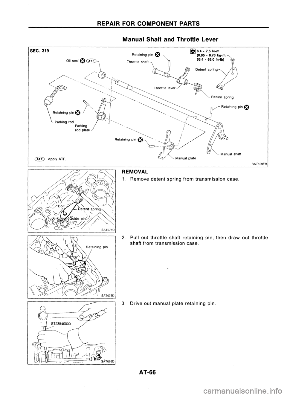
SEC.319
c&D:
ApplyATF. REPAIR
FORCOMPONENT PARTS
Manual ShaftandThrottle Lever
~ 6.4•7.5 N.m
Retaining pm~~ (0.65-0.76 kg-m. "-
Throttle shaft ~ 56.4-66.0 In-Ib)
f
~ 0.""
''''0'''11)
Th""'. ,,~,/ ,
V
~ Return spnng
~ Retaining pin~
)
SAT109EB
REMOVAL
1. Remove detentspringfromtransmission case.
2. Pullout throttleshaftretaining pin,then draw outthrottle
shaft fromtransmission case.
3. Drive outmanual plateretaining pin.
AT-66
Page 67 of 1701

4. Drive andthen pulloutparking rodplate retaining pin.
5. Remove parkingrodplate frommanual shaft.
6. Draw outparking rodfrom trans")
REPAIRFORCOMPONENT PARTS
Manual ShaftandThrottle Lever(ConI'd)
4. Drive andthen pulloutparking rodplate retaining pin.
5. Remove parkingrodplate frommanual shaft.
6. Draw outparking rodfrom transmission case.
7. Pull outmanual shaftretaining pin. •
8. Remove manualshaftandmanual platefromtransmission
i
case.
9. Remove manualshaftoilseal.
SATOBOD
INSPECTION
• Check component partsforwear ordamage. Replaceif
necessary.
AT-67