differential NISSAN ALMERA N15 1995 Service Manual
[x] Cancel search | Manufacturer: NISSAN, Model Year: 1995, Model line: ALMERA N15, Model: NISSAN ALMERA N15 1995Pages: 1701, PDF Size: 82.27 MB
Page 1 of 1701
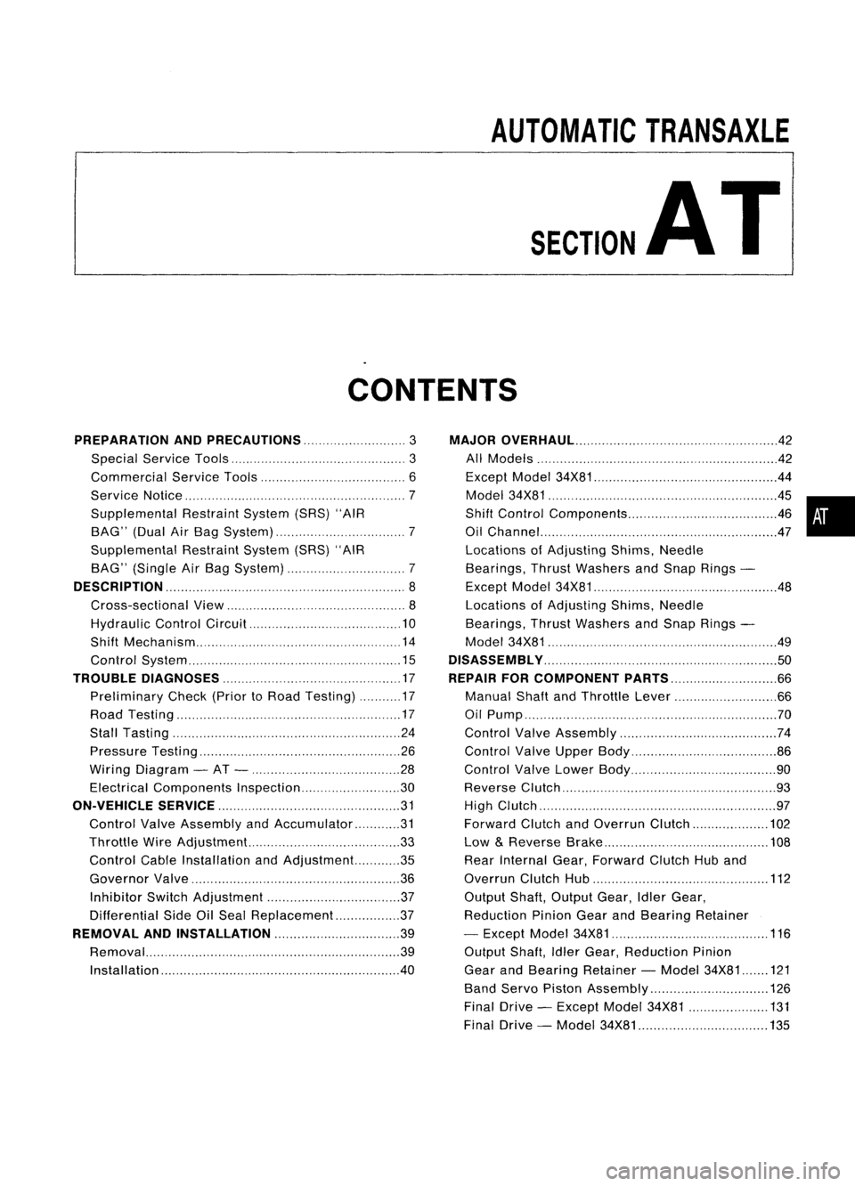
AUTOMATICTRANSAXLE
SECTION
AT
CONTENTS
PREPARATION ANDPRECAUTIONS
3
Special Service Tools 3
Commercial ServiceTools 6
Service Notice 7
Supplemental RestraintSystem(SRS)"AIR
BAG" (DualAirBag System) 7
Supplemental RestraintSystem(SRS)"AIR
BAG" (Single AirBag System) 7
DESCRIPTION
8
Cross-sectional View 8
Hydraulic ControlCircuit 10
Shift Mechanism 14
Control System 15
TROUBLE DIAGNOSES 17
Preliminary Check(PriortoRoad Testing) 17
Road Testing 17
Stall Tasting 24
Pressure Testing 26
Wiring Diagram -AT - 28
Electrical Components Inspection 30
ON-VEHICLE SERVICE 31
Control ValveAssembly andAccumulator 31
Throttle WireAdjustment.. 33
Control CableInstallation andAdjustment 35
Governor Valve 36
Inhibitor SwitchAdjustment 37
Differential SideOilSeal Replacement.. 37
REMOVAL ANDINSTALLATION
39
Removal 39
Installation .40MAJOR
OVERHAUL.. 42
All Models 42
Except Model34X81 .44
Model 34X81 45•
Shift Control Components 46
i
Oil Channel 47
Locations ofAdjusting Shims,Needle
Bearings, ThrustWashers andSnap Rings -
Except Model34X81 .48
Locations ofAdjusting Shims,Needle
Bearings, ThrustWashers andSnap Rings -
Model 34X81 .49
DiSASSEMBLy 50
REPAIR FORCOMPONENT PARTS 66
Manual ShaftandThrottle Lever 66
Oil Pump 70
Control ValveAssembly 74
Control ValveUpper Body 86
Control ValveLower Body 90
Reverse Clutch 93
High Clutch 97
Forward ClutchandOverrun Clutch 102
Low &Reverse Brake 108
Rear Internal Gear,Forward ClutchHuband
Overrun ClutchHub 112
Output Shaft,Output Gear,IdlerGear,
Reduction PinionGearandBearing Retainer
- Except Model34X81 116
Output Shaft,IdlerGear, Reduction Pinion
Gear andBearing Retainer -Model 34X81 121
Band Servo Piston Assembly 126
Final Drive -Except Model34X81 131
Final Drive -Model 34X81 135
Page 3 of 1701
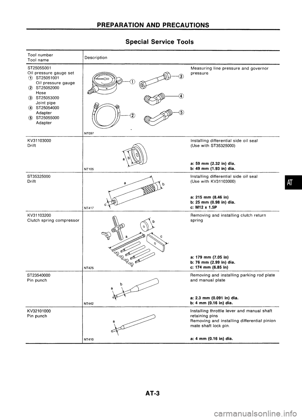
Toolnumber
Tool name
PREPARATION
ANDPRECAUTIONS
Special Service Tools
Description
8T25058001
Oil pressure gaugeset
G)
8T25051001
Oil pressure gauge
@ 8T25052000
Hose
@
8T25053000
Joint pipe
@
8T25054000
Adapter
@
8T25055000
Adapter Measuring
linepressure andgovernor
pressure
NT097
KV31103000
Drift
8T35325000 Drift
KV31103200
Clutch spring compressor
8T23540000 Pin punch
KV32101000
Pin punch
NT105
NT417
NT425
NT442
NT410
AT-3
Installing
differential sideoilseal
(Use with8T35325000)
a: 59 mm (2.32 in)dia.
b: 49 mm (1.93 in)dia.
Installing differential sideoilseal
(Use withKV31103000)
a: 215 mm (8.46 in)
b: 25 mm (0.98 in)dia.
c: M12 x1.5P
Removing andinstalling clutchreturn
spring
a: 179 mm (7.05 in)
b: 76 mm (2.99 in)dia.
c: 174 mm (6.85 in)
Removing andinstalling parkingrodplate
and manual plate
a: 2.3 mm (0.091 in)dia.
b: 4mm (0.16 in)dia.
Installing throttleleverandmanual shaft
retaining pins
Removing andinstalling differential pinion
mate shaft lockpin.
a: 4mm (0.16 in)dia.
•
Page 4 of 1701
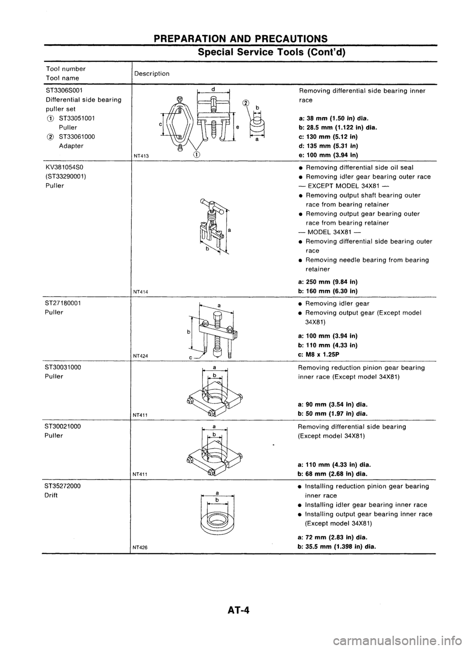
Toolnumber
Tool name
PREPARATION
ANDPRECAUTIONS
Special Service Tools(Cont'd)
Description
ST3306S001
Differential sidebearing
puller set
CD
ST33051 001
Puller
@
ST33061000
Adapter
KV381054S0
(ST33290001) Puller
NT413
NT414 ,~
a
Removing
differential sidebearing inner
race
a: 38 mm (1.50 in)dia.
b: 28.5 mm(1.122 in)dia.
c: 130 mm (5.12 in)
d: 135 mm (5.31 in)
e: 100 mm (3.94 In)
• Removing differential sideoilseal
• Removing idlergear bearing outerrace
- EXCEPT MODEL34X81-
• Removing outputshaftbearing outer
race from bearing retainer
• Removing outputgearbearing outer
race from bearing retainer
- MODEL 34X81-
• Removing differential sidebearing outer
race
• Removing needlebearing frombearing
retainer
a: 250 mm (9.84 in)
b: 160 mm (6.30 in)
ST27180001 Puller
NT424
ST30031000 Puller
NT411
ST30021 000
Puller
NT411
ST35272000 Drift
~
NT426
AT-4
•
Removing idlergear
• Removing outputgear(Except model
34X81)
a: 100 mm (3.94 In)
b: 110 mm (4.33 in)
c: M8 x1.25P
Removing reductionpiniongearbearing
inner race(Except model34X81)
a: 90 mm (3.54 In)dia.
b: 50 mm (1.97 in)dia.
Removing differential sidebearing
(Except model34X81)
a: 110 mm (4.33 in)dia.
b: 68 mm (2.68 in)dia.
• Installing reduction piniongearbearing
inner race
• Installing idlergear bearing innerrace
• Installing outputgearbearing innerrace
(Except model34X81)
a: 72 mm (2.83 in)dia.
b: 35.5 mm(1.398 in)dia.
Page 5 of 1701
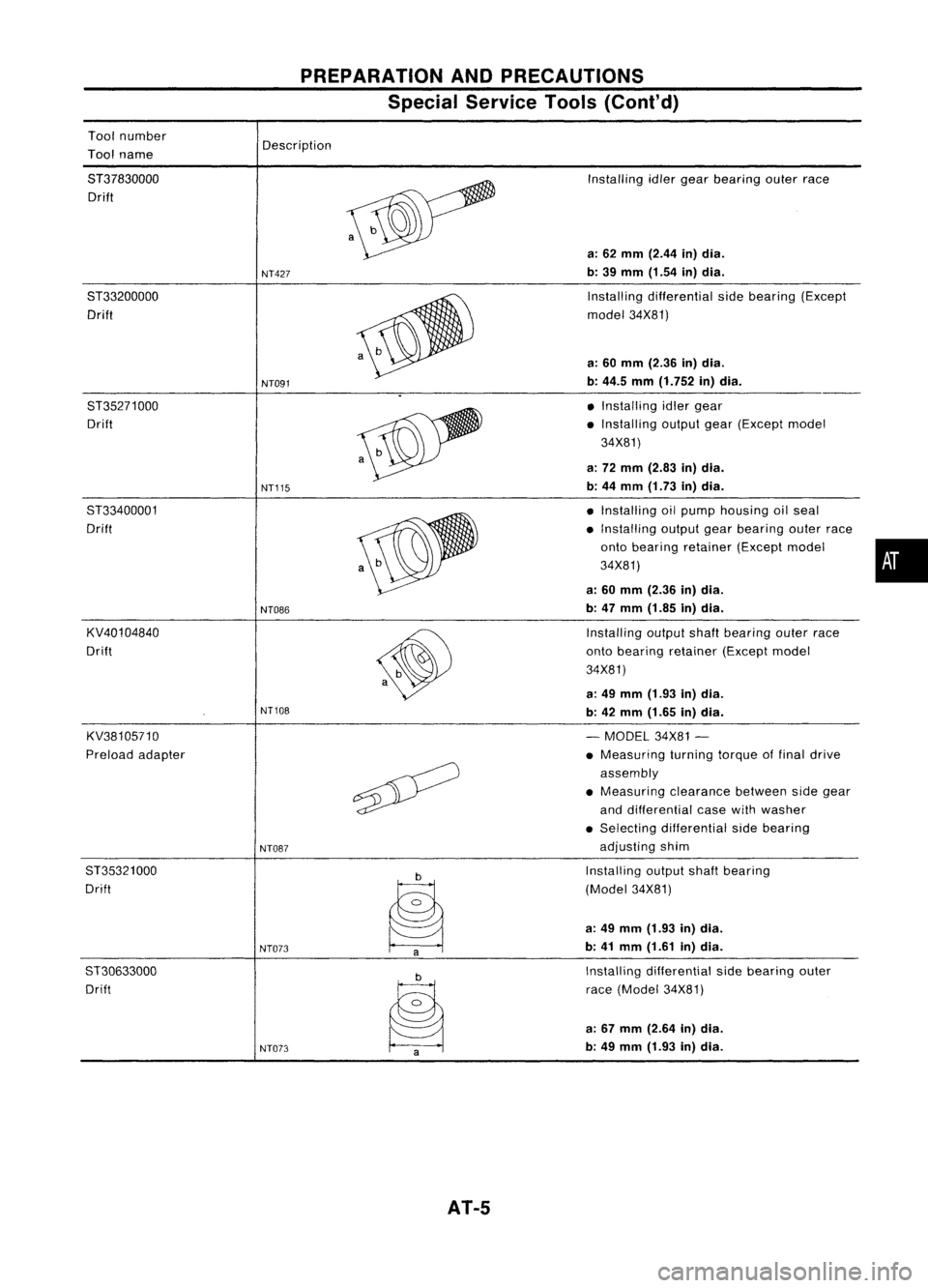
Toolnumber
Tool name
PREPARATION
ANDPRECAUTIONS
Special Service Tools(Cont'd)
Description
8T37830000 Drift
8T33200000 Drift
8T35271000 Drift
8T33400001
Drift
KV40104840
Drift
KV38105710
Preload adapter
8T35321000
Drift
ST30633000 Drift
NT427
NT091
NT115
NT086
NT108
NT087
NT073 NT073
AT-5
Installing
idlergear bearing outerrace
a: 62 mm (2.44 in)dia.
b: 39 mm (1.54 in)dia.
Installing differential sidebearing (Except
model 34X81)
a: 60 mm (2.36 in)dia.
b: 44.5 mm(1.752 in)dia.
• Installing idlergear
• Installing outputgear(Except model
34X81)
a: 72 mm (2.83 in)dia.
b: 44 mm (1.73 in)dia.
• Installing oilpump housing oilseal
• Installing outputgearbearing outerrace
onto bearing retainer (Exceptmodel •
34X81)
a: 60 mm (2.36 in)dia.
b: 47 mm (1.85 in)dia.
Installing outputshaftbearing outerrace
onto bearing retainer (Exceptmodel
34X81)
a: 49 mm (1.93 in)dia.
b: 42 mm (1.65 in)dia.
- MODEL 34X81-
• Measuring turningtorqueoffinal drive
assembly
• Measuring clearancebetweensidegear
and differential casewithwasher
• Selecting differential sidebearing
adjusting shim
Installing outputshaftbearing
(Model 34X81)
a: 49 mm (1.93 in)dia.
b: 41 mm (1.61 in)dia.
Installing differential sidebearing outer
race (Model 34X81)
a: 67 mm (2.64 in)dia.
b: 49 mm (1.93 in)dia.
Page 6 of 1701
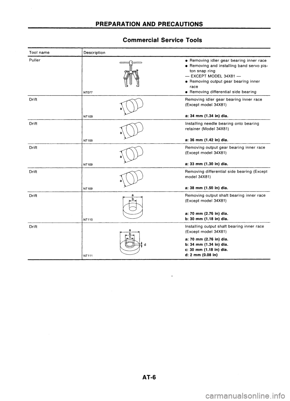
PREPARATIONANDPRECAUTIONS
Commercial ServiceTools
Tool name
Description
Puller •Removing idlergear bearing innerrace
• Removing andinstalling bandservo pis-
=m
ton
snap ring
o
0
-
EXCEPT MODEL34X81-
• Removing outputgearbearing inner
race
NT077
•
Removing differential sidebearing
Drift
~
Removing
idlergear bearing innerrace
(Except model34X81)
a: 34 mm (1.34 in)dia.
NT109
Drift
~
Installing
needlebearing ontobearing
retainer (Model34X81)
a: 36 mm (1.42 in)dia.
NT109
Drift
~
Removing
outputgearbearing innerrace
(Except model34X81)
a: 33 mm (1.30 in)dia.
NT109
Drift
~
Removing
differential sidebearing (Except
model 34X81)
a: 38 mm (1.50 in)dia.
NT109
Drift
~
Removing
outputshaftbearing innerrace
(Except model34X81)
a: 70 mm (2.76 in)dia.
NT110
b:
30 mm (1.18 in)dia.
Drift Installing
outputshaftbearing innerrace
~d
(Except
model34X81)
a: 70 mm (2.76 in)dia.
b: 34 mm (1.34 in)dia.
c: 30 mm (1.18 in)dia.
NT111
d:
2mm (0.08 in)
AT-6
Page 9 of 1701
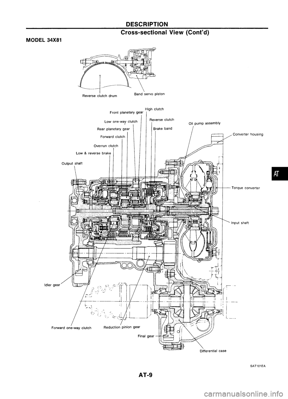
MODEL34X81 DESCRIPTION
Cross-sectional View(Cant' d)
Reverse clutchdrum Band
servo piston
High clutch
Front planetary gear
Reduction piniongear
Low
&
reverse brake
Idler gear
Forward one-way clutch Low
one-way clutch
Rear planetary gear
Forward clutch
Overrun clutch
,"'I
Reverse
clutch
Brake band
Final gear
AT-9
Oil
pump assembly
Converterhousing
Torque converter
Input shaft
c
...
-;-
I
L_
Differential case
SAT101EA
•
Page 37 of 1701

InhibitorSwitchAdjustment
1. Remove controlcableendfrom manual shaft.
2. Set manual shaftin"N" position.
3." Loosen inhibitor switchfixingbolts.
Use a4 mm (0.16 in)pin forthis adjustment. •
Insert thepinstraight intothemanual shaftadjustment hole.
Rotate inhibitor switchuntilthepincan also beinserted
straight intohole ininhibitor switch.
Tighten inhibitor switchfixingbolts.
Remove pinfrom adjustment holeafter adjusting inhibitor
switch.
Reinstall anypart removed.
Adjust control cable-Refer to"Control CableInstallation
and Adjustment", AT-35.
Check continuity ofinhibitor switch-Refer to"Electrical
Components Inspection",AT-30.
ON-VEHICLE
SERVICE
Governor Valve(Cont'd)
4. Remove governor valveassembly fromtransaxle.
5. Check governor valveassembly ifnecessary -Refer to
"DISASSEMBLY", AT-65.
4. a.b.
5.
6.
7.
8.
SAT580E 9.
Differential SideOilSeal Replacement
1. Remove driveshaftassemblies. -Refer toFA section
("Removal", "FRONTAXLE-Drive Shaft").
2. Remove oilseals.
AT-37
Page 38 of 1701

Converterhousingside(RHS)
Transmission caseside(LHS)
SAT259EA ON-VEHICLE
SERVICE
Differential SideOilSeal Replacement (Cont'd)
3. Install oilseals.
• Apply ATFtooil seal surface beforeinstalling.
Converter housing
side •
Install oilseals sothat dimensions
"A"
and
"8"
arewithin
specifications.
Transmission
case side
B
Oil
seal Oil
seal
A
SAT639D
A
5.5 -6.5 (0.217 -0.256)
4. Reinstall anypart removed.
AT-38
Unit:
mm(in)
B
0.5 (0.020)
or
less
Page 47 of 1701

MAJOROVERHAUL
Oil Channel
High clutch pressure
Oilcooler tube(OUT) hole
•
Oil
cooler tube
(IN)
Torque converter pressure
(Lock-up applied)
" Servo
4th
apply chamber pressure
Servo 2ndapply chamber pressure
• Servo 3rdrelease
chamber pressure
Torque
converter pressure
(Lock-up released)
SIR accumulator shoulderpressure
SIR accumulator backpressure
(Reverse clutchpressure)
Oil cooler tube
(IN)
hole
Torque
converter
pressure (Lock-up applied)
Torque converter
pressure (Lock-up released)
reverse
brakepressure
Overrun clutchpressure
Forward clutchpressure
High
clutch pressure
Reverse clutch
pressure
Oil pump suction hole
Differential lubricanthole
High clutch pressure
Oil pump discharge hole
Reverse clutch
pressure
Oil pump suction hole
Reverse
clutch
pressure
Low
&
Oil
pump suction hole
Oil pump discharge hole
Forward clutchpressure
Overrun clutchpressure
Low
&
reverse brake
pressure
Torque
converter pressure
(Lock-up released)
Torque converter
pressure (Lock-up applied)
Governor pressure
Linepressure
SAT586DC
AT-47
Page 54 of 1701

DISASSEMBLV
21. Remove throttlewirefrom throttle lever.
22. Remove throttlewiremounting bolt.
23. Draw outthrottle wirefrom transmission case.
- All models -
24. Remove converter housingaccording tothe following pro-
cedures.
a. Remove converter housingmounting bolts@and
CID.
b. Remove converter housing.
c. Remove O-ringfromdifferential oilport.
AT-54