differential NISSAN ALMERA N15 1995 Owner's Guide
[x] Cancel search | Manufacturer: NISSAN, Model Year: 1995, Model line: ALMERA N15, Model: NISSAN ALMERA N15 1995Pages: 1701, PDF Size: 82.27 MB
Page 1491 of 1701
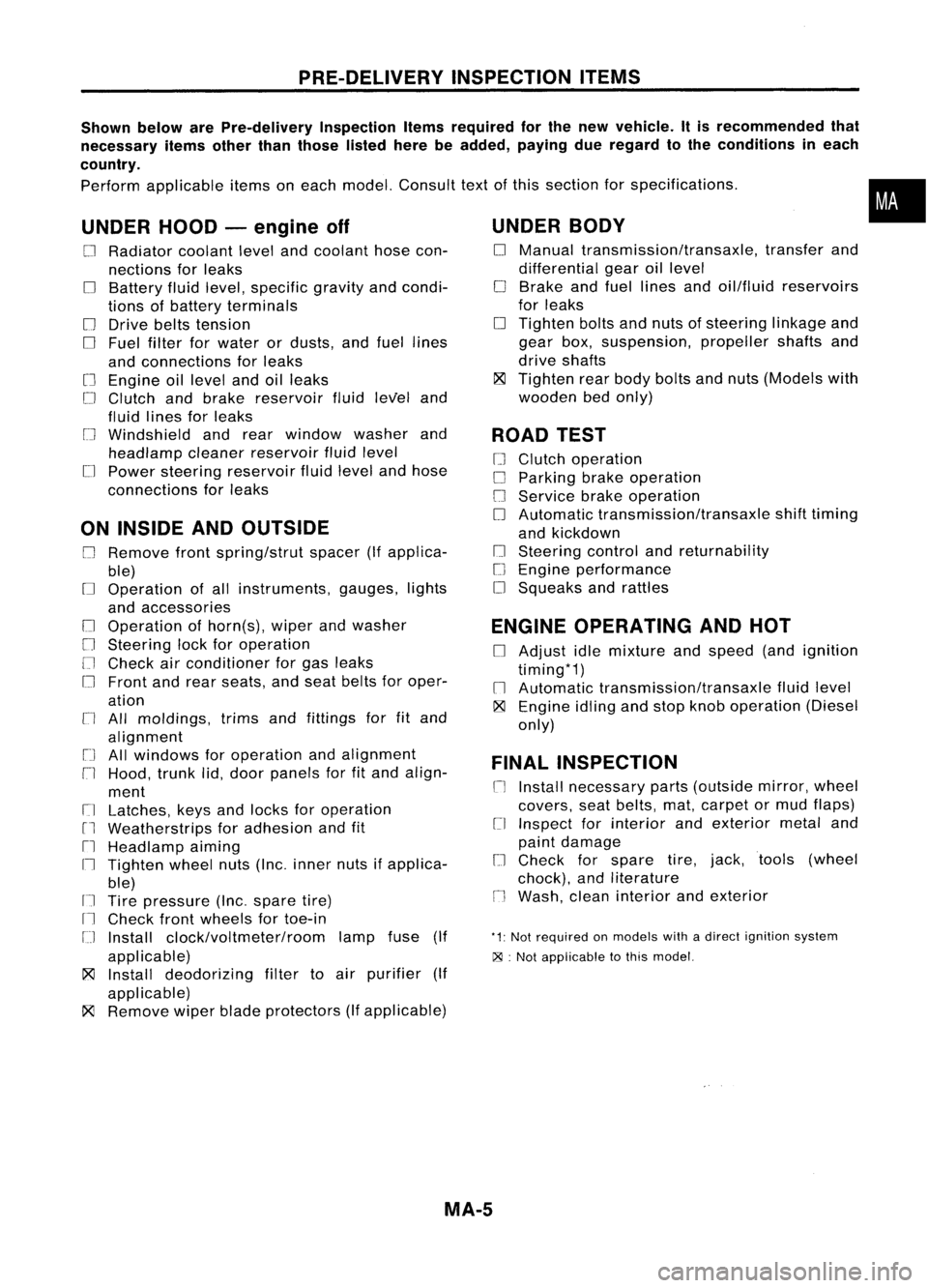
PRE-DELIVERYINSPECTIONITEMS
Shown belowarePre-delivery InspectionItemsrequired forthe new vehicle. Itis recommended that
necessary itemsotherthanthose listedherebeadded, payingdueregard tothe conditions ineach
country.
Perform applicable itemsoneach model. Consult textofthis section forspecifications .
UNDER HOOD-engine off
o
Radiator coolantlevelandcoolant hosecon-
nections forleaks
o
Battery fluidlevel, specific gravityandcondi-
tions ofbattery terminals
o
Drive beltstension
D
Fuel filter forwater ordusts, andfuel lines
and connections forleaks
[] Engine oillevel andoilleaks
D
Clutch andbrake reservoir fluidlevel and
fluid lines forleaks
o
Windshield andrear window washerand
headlamp cleanerreservoir fluidlevel
D
Power steering reservoir fluidlevel andhose
connections forleaks
ON INSIDE ANDOUTSIDE
D
Remove frontspring/strut spacer(Ifapplica-
ble)
D
Operation ofall instruments, gauges,lights
and accessories
o
Operation ofhorn(s), wiperandwasher
[] Steering lockforoperation
[] Check airconditioner forgas leaks
o
Front andrear seats, andseat belts foroper-
ation
n
All moldings, trimsandfittings forfitand
alignment
[J
Allwindows foroperation andalignment
n
Hood, trunklid,door panels forfitand align-
ment
[1
Latches, keysandlocks foroperation
rl
Weatherstrips foradhesion andfit
[l
Headlamp aiming
I~ Tighten wheelnuts(Inc. inner nutsifapplica-
ble)
IJ Tire pressure (Inc.spare tire)
Il
Check frontwheels fortoe-in
IJ Install clock/voltmeter/room lampfuse(If
applicable)
~ Install deodorizing filtertoair purifier (If
applicable)
~ Remove wiperbladeprotectors (Ifapplicable)
UNDER
BODY
o
Manual transmission/transaxle, transferand
differential gearoillevel
D
Brake andfuel lines andoil/fluid reservoirs
for leaks
D
Tighten boltsandnuts ofsteering linkageand
gear box,suspension, propellershaftsand
drive shafts
~ Tighten rearbody boltsandnuts (Models with
wooden bedonly)
ROAD TEST
D
Clutch operation
D
Parking brakeoperation
[J
Service brakeoperation
D
Automatic transmission/transaxle shifttiming
and kickdown
[] Steering controlandreturnability
o
Engine performance
D
Squeaks andrattles
ENGINE OPERATING ANDHOT
D
Adjust idlemixture andspeed (andignition
timing*1)
n
Automatic transmission/transaxle fluidlevel
~ Engine idlingandstop knob operation (Diesel
only)
FINAL INSPECTION
n
Install necessary parts(outside mirror,wheel
covers, seatbelts, mat,carpet ormud flaps)
[1
Inspect forinterior andexterior metaland
paint damage
[] Check forspare tire,jack, tools (wheel
chock), andliterature
n
Wash, cleaninterior andexterior
"1: Not required onmodels withadirect ignition system
~ :Not appiicable tothis model.
•
MA-5
Page 1543 of 1701
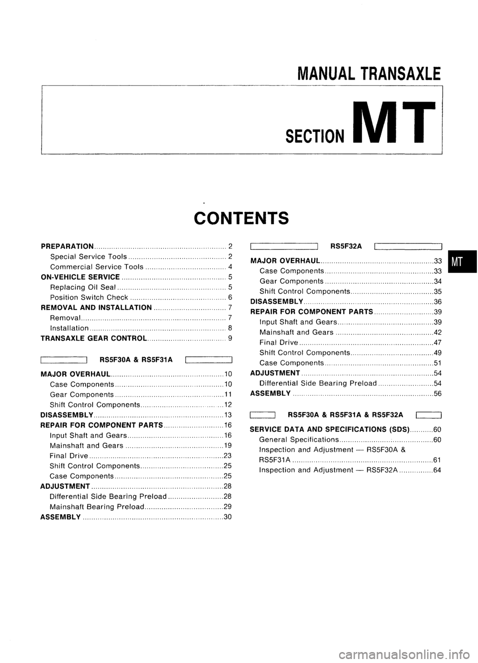
MANUALTRANSAXLE
SECTION
MT
CONTENTS
PREPARATION 2
Special Service Tools 2
Commercial ServiceTools 4
ON-VEHICLE SERVICE
5
Replacing OilSeal 5
Position SwitchCheck 6
REMOVAL ANDINSTAllATION 7
Removal ,7
Installation '8
TRANSAXlE GEARCONTROL 9
RS5F30A
&
RS5F31 A
MAJOR OVERHAUL 10
Case Components 10
Gear Components ,11
Shift Control Components , 12
DiSASSEMBly ,13
REPAIR FORCOMPONENT PARTS 16
Input Shaft andGears 16
Mainshaft andGears 19
Final Drive ,,23
Shift Control Components 25
Case Components ,25
ADJUSTMENT ,,.. , 28
Differential SideBearing Preload 28
Mainshaft BearingPreload ,29
ASSEMBly ,30 RS5F32A
MAJOR OVERHAUl ,,,
33
Case Components , 33
Gear Components 34
Shift Control Components 35
DiSASSEMBly ",.,., , ,36
REPAIR FORCOMPONENT PARTS 39
Input Shaft andGears 39
Mainshaft andGears 42
Final Drive .47
Shift Control Components 49
Case Components ' 51
ADJUSTMENT ,, ", 54
Differential SideBearing Preload ,54
ASSEMBLY ',
56
'----_-JI RS5F30A
&
RS5F31A
&
RS5F32A
SERVICE DATAANDSPECIFICATIONS (SDS)60
General Specifications 60
Inspection andAdjustment -RS5F30A &
RS5F31 A ' 61
Inspection andAdjustment -RS5F32A 64
•
Page 1544 of 1701
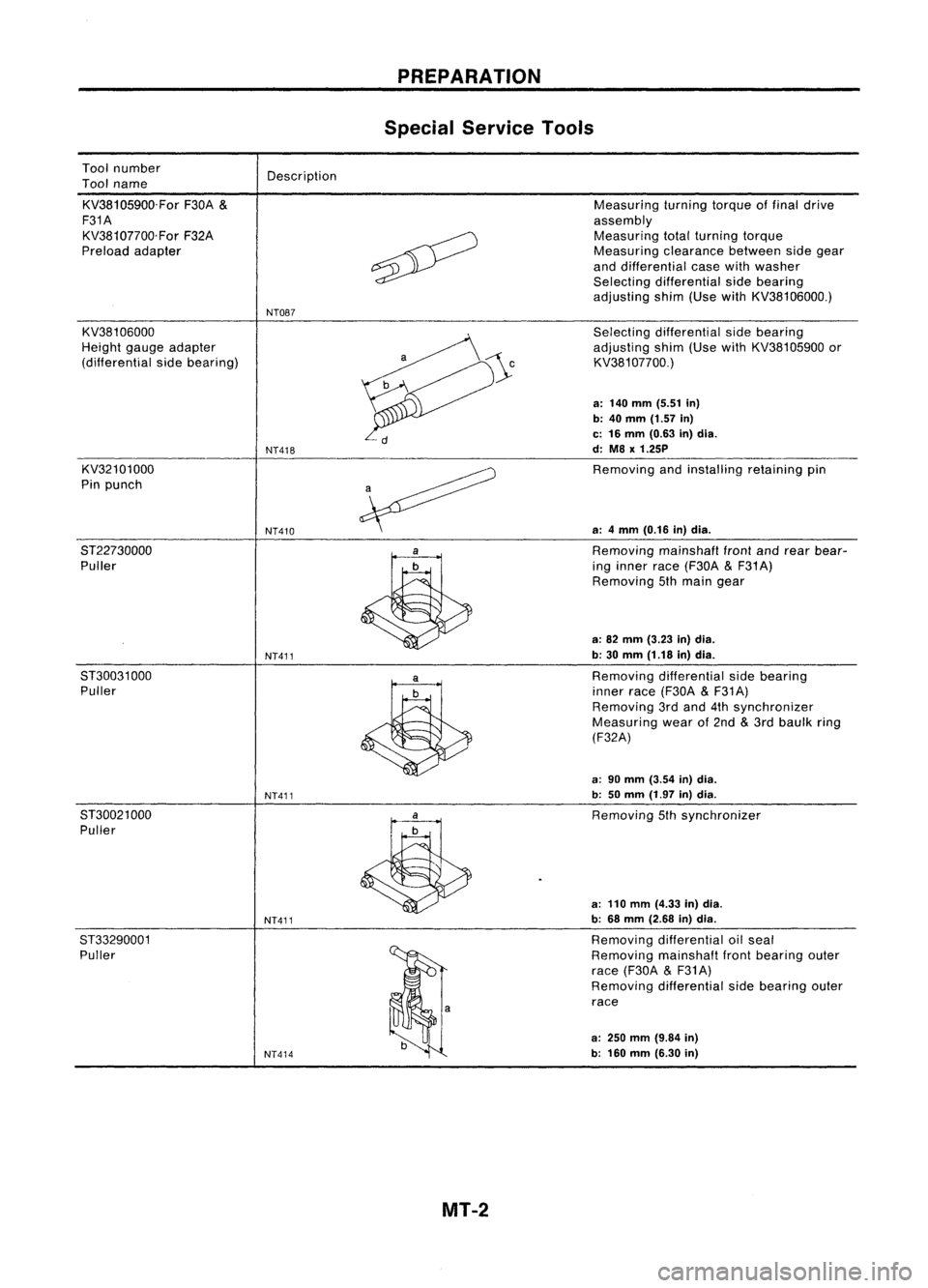
Toolnumber
Tool name
KV38105900.For F30A
&
F31A KV38107700.For F32A
Preload adapter Description
NT087 PREPARATION
Special Service Tools
Measuring turningtorqueoffinal drive
assembly Measuring totalturning torque
Measuring clearancebetweensidegear
and differential casewithwasher
Selecting differential sidebearing
adjusting shim(UsewithKV38106000.)
KV38106000
Height gaugeadapter
(differential sidebearing)
KV32101000
Pin punch
8T22730000 Puller
8T30031 000
Puller
8T30021 000
Puller
ST33290001 Puller
NT418
NT410
NT411
NT411
NT411
NT414
Selecting
differential sidebearing
adjusting shim(UsewithKV38105900 or
KV381 07700.)
a: 140 mm (5.51 in)
b: 40
mm
(1.57
in)
c: 16 mm (0.63 in)dia.
d: M8
x
1.25P
Removing andinstalling retainingpin
a: 4mm (0.16 in)dia.
Removing mainshafl
front
andrear bear-
ing inner race(F30A
&
F31 A)
Removing 5thmain gear
a: 82 mm (3.23 in)dia.
b: 30 mm (1.18 in)dia.
Removing differential sidebearing
inner race(F30A
&
F31A)
Removing 3rdand 4thsynchronizer
Measuring wearof2nd
&
3rd baulk ring
(F32A)
a: 90 mm (3.54 in)dia.
b: 50mm (1.97 in)dia.
Removing 5thsynchronizer
a: 110 mm (4.33 in)dia.
b: 68 mm (2.68 in)dia.
Removing differential oilseal
Removing mainshaflfrontbearing outer
race (F30A
&
F31A)
Removing differential sidebearing outer
race
a:
250
mm
(9.84
in)
b: 160 mm (6.30 in)
MT-2
Page 1545 of 1701
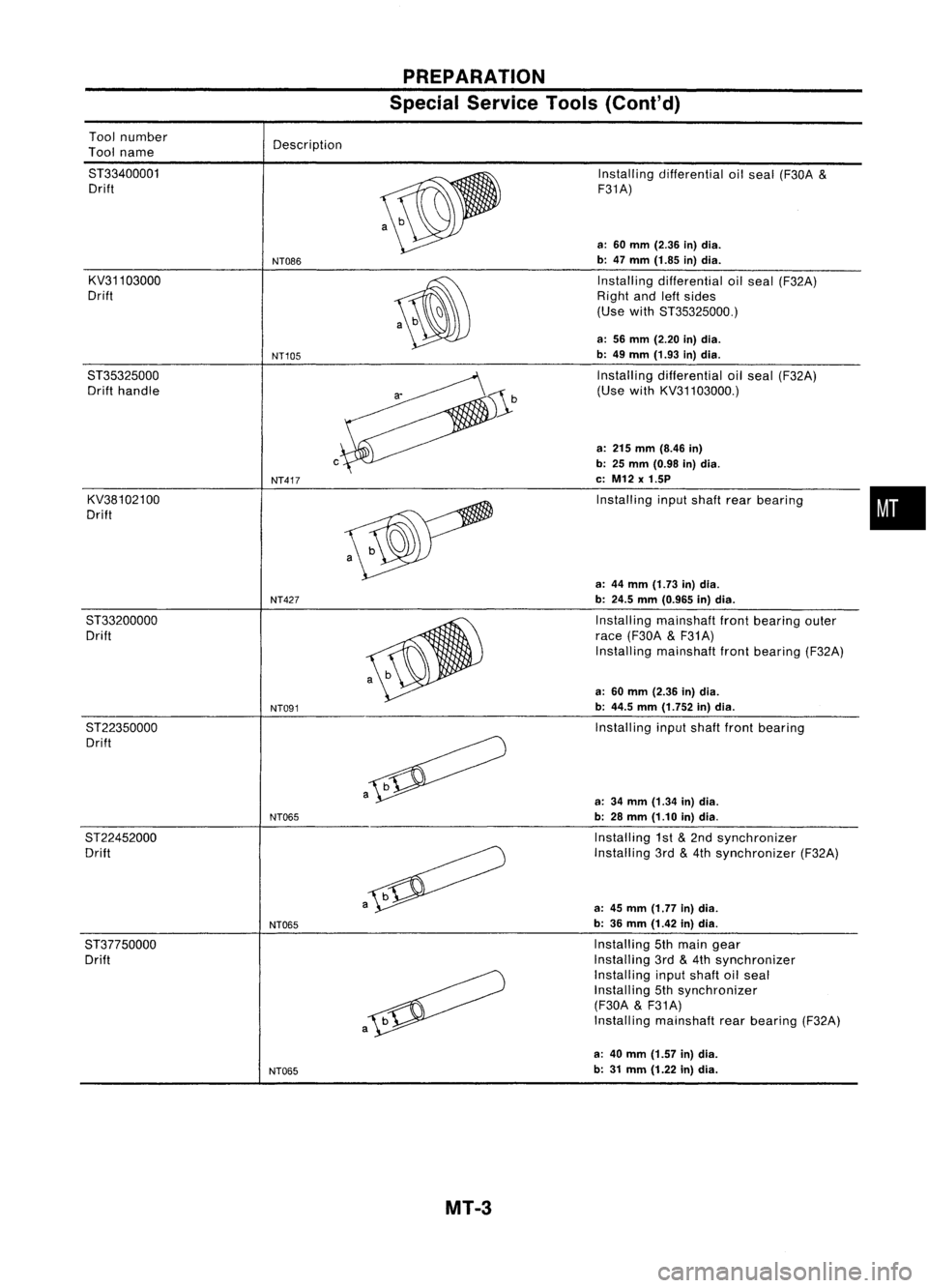
PREPARATION
Special Service Tools(Coni'd)
a-
Tool
number
Tool name
ST33400001 Drift
KV31103000
Drift
ST35325000 Drift handle
KV38102100
Drift Description
NT086
NT105
c
NT417
Installing
differential oilseal (F30A
&
F31A)
a: 60 mm (2.36 in)dia.
b: 47 mm (1.85 in)dia.
Installing differential oilseal (F32A)
Right andleftsides
(Use withST35325000.)
a: 56 mm (2.20 in)dia.
b: 49 mm (1.93 in)dia.
Installing differential oilseal (F32A)
(Use withKV31103000.)
a: 215 mm (8.46 in)
b: 25 mm (0.98 in)dia.
c: M12 x1.5P
Installing inputshaft rearbearing
•
a: 44 mm (1.73 in)dia.
NT427
b:24.5 mm(0.965 in)dia.
ST33200000 Installingmainshaft frontbearing outer
Drift race(F30A
&
F31A)
Installing mainshaft frontbearing (F32A)
a: 60 mm (2.36 in)dia.
NT091
b:
44.5 mm(1.752 in)dia.
ST22350000 Installinginputshaft frontbearing
Drift
a
a:34 mm (1.34 in)dia.
NT065
b:28 mm (1.10 in)dia.
ST22452000 Installing1st
&
2nd synchronizer
Drift Installing3rd
&
4th synchronizer (F32A)
a
a:45 mm (1.77 in)dia.
NT065
b:
36 mm (1.42 in)dia.
ST37750000 Installing5thmain gear
Drift Installing
3rd
&
4th synchronizer
Installing inputshaft oilseal
Installing 5thsynchronizer
(F30A
&
F31A)
a
Install
ingmainshaft rearbearing (F32A)
a: 40 mm (1.57 in)dia.
NT065
b:
31 mm (1.22 in)dia.
MT-3
Page 1546 of 1701
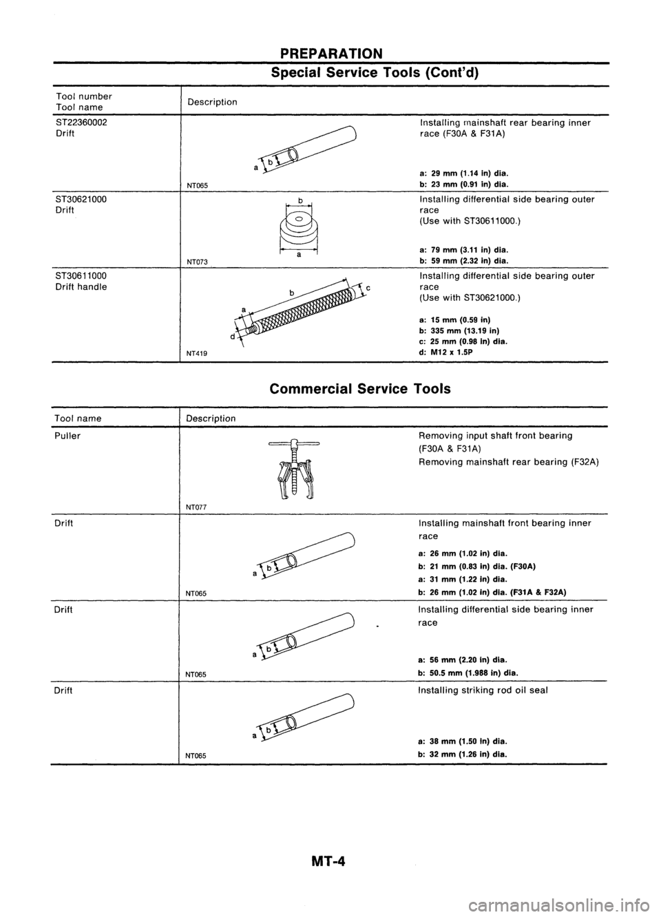
PREPARATION
Special Service Tools(Coni'd)
Tool number
Tool name
ST22360002 Drift
ST30621000 Drift
ST30611000 Drift handle Description
NT065
NT073
NT419 a
~a
Installing
rnainshaft rearbearing inner
race (F30A
&
F31A)
a:
29
mm
(1.14
in)dia.
b: 23 mm (0.91 in)dia.
Installing differential sidebearing outer
race
(Use withST30611000.)
a: 79 mm (3.11 in)dia.
b: 59mm (2.32 in)dia.
Installing differential sidebearing outer
race
(Use withST30621000.)
a: 15mm (0.59 in)
b: 335 mm (13.19 in)
c: 25 mm (0.98 In)dia.
d: M12 x1.5P
Commercial ServiceTools
Tool name
Description
Puller
m:
o
0
NT077
Drift
Drift
Drift
NT065
NT065
NT065 a
Removing
inputshaft frontbearing
(F30A
&
F31A)
Removing mainshaftrearbearing (F32A)
Installing mainshaft frontbearing inner
race
a: 26mm (1.02 in)dia.
b: 21mm (0.83 in)dia. (F30A)
a: 31mm (1.22 in)dia.
b: 26 mm (1.02 in)dia. (F31A
&
F32A)
Installing differential sidebearing inner
race
a: 56mm (2.20 In)dia.
b: 50.5 mm(1.988 in)dia.
Installing strikingrodoilseal
a: 38 mm (1.50 In)dia.
b: 32 mm (1.26 in)dla.
MT-4
Page 1547 of 1701
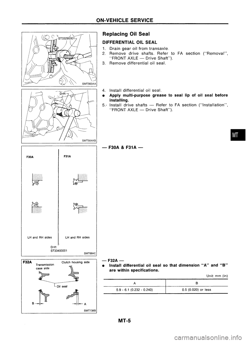
ON-VEHICLESERVICE
Replacing OilSeal
DIFFERENTIAL OILSEAL
1. Drain gearoilfrom transaxle.
2. Remove driveshafts. RefertoFA section ("Removal",
"FRONT AXLE-Drive Shaft").
3. Remove differential oilseal.
4. Install differential oilseal.
• Apply multi-purpose greasetoseal lipofoil seal before
installing.
5.- Install driveshafts -Refer toFA section ("Installation",
"FRONT AXLE-Drive Shaft").
- F30A
&
F31A-
•
F30A F31A
LH and RHsides LHand RHsides
Drift
ST33400001
SMT684C
.P
-F32A
-
• Install differential oilseal sothat dimension "A"and"B"
are within specifications.
F32A
Transmission
case side Clutch
housing side
Oil seal
SMT7388
A
5.9 -6.1 (0.232 -0.240)
MT-5
Unit:
mm(in)
B
0.5 (0.020)
or
less
Page 1552 of 1701
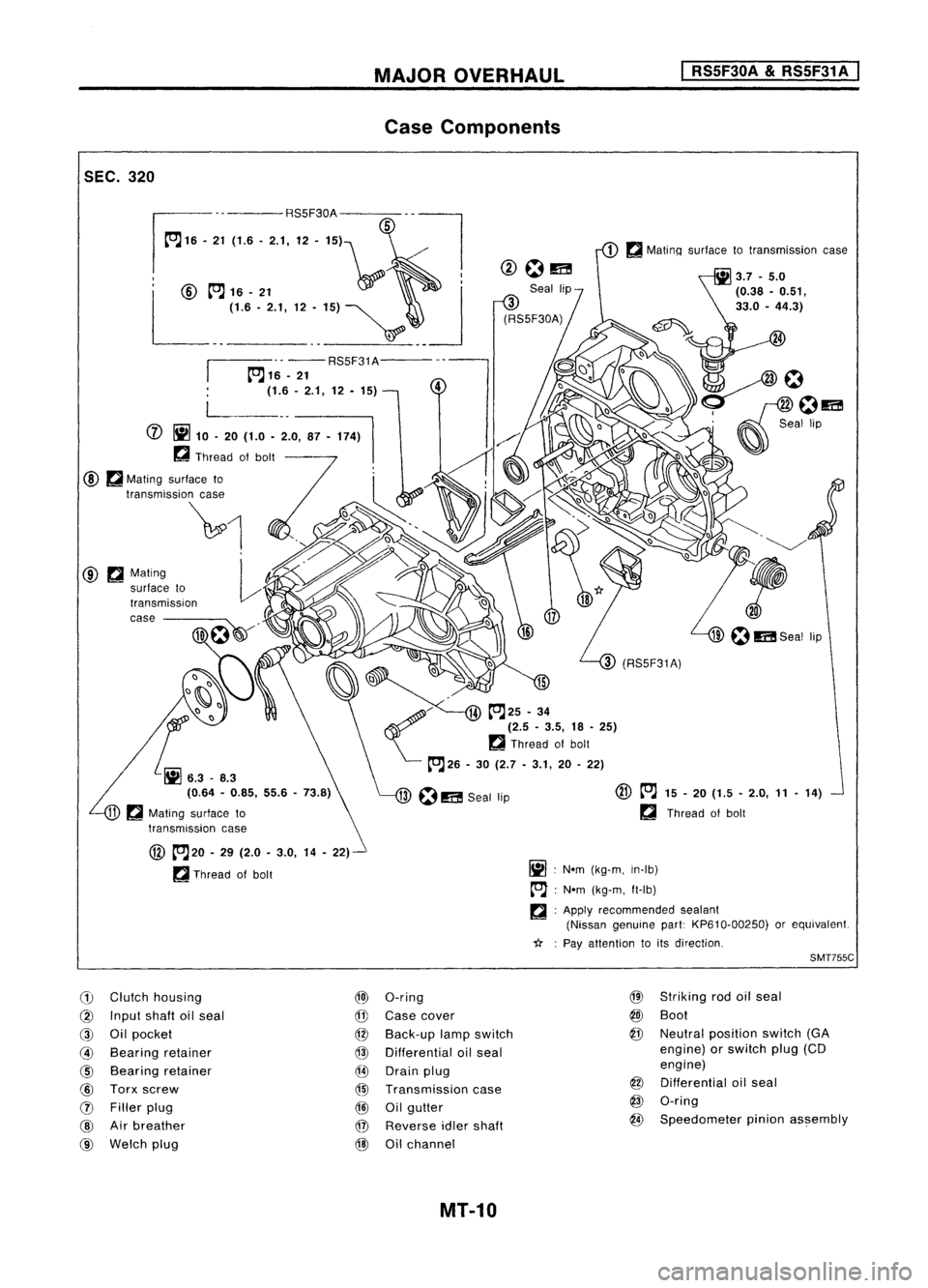
SEC.320 MAJOR
OVERHAUL
Case Components
I
RS5F30A
&
RS5F31 A
I
.. -- RS5F31A---
~16 -21
(1.6 -2.1, 12. 15)
@ ~Mating
surface to
transmiSSion
case ----
@
~20 -29 (2.0 -3.0, 14-22)-
~ Thread ofbolt
(1)
Clutch housing
@)
O-ring
@
Input shaftoilseal
@
Case cover
@
Oilpocket
@
Back-up lampswitch
@
Bearing retainer
@
Differential oilseal
@
Bearing retainer
@
Drain plug
@
Torx screw
@l
Transmission case
(J)
Filler plug
@
Oilgutter
@
Airbreather
@
Reverse idlershaft
@
Welch plug
@
Oilchannel
MT-10
@
~
15-20 (1.5 -2.0, 11-14)
~ Thread ofbolt
Ij] :
Nom (kg-m, in-Ib)
tr'J :
Nom (kg-m, ft-Ib)
~ :Apply recommended sealant
(Nissan genuine part:KP610-00250) orequivalent.
*: :
Pay attention toits direction.
SMT755C
@
Striking rodoilseal
@J
Boot
@
Neutral position switch(GA
engine) orswitch plug(CD
engine)
@
Differential oilseal
@
O-ring
@
Speedometer pinionassembly
Page 1553 of 1701
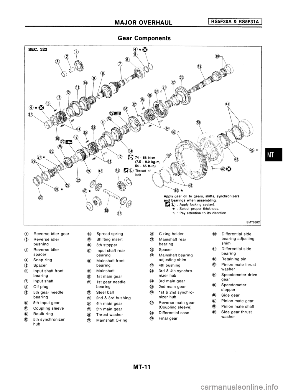
MAJOROVERHAUL
I
RS5F30A
&
RS5F31 A
I
SEC. 322
G)
Reverse
idlergear
@
Spread spring
@
Reverse idler
@
Shifting insert
bushing
@
5thstopper
@
Reverse idler
@
Input shaft rear
spacer bearing
@
Snap ring
@
Mainshaft front
@
Spacer bearing
@
Input shaftfront
@l
Mainshaft
bearing
@J
1st
main gear
(]) Input shaft
@
1stgear needle
@
Oilplug bearing
@
5th
gear needle
@
Steel ball
bearing
@
2nd
&
3rd bushing
@
5thinput gear
@
4thmain gear
@
Coupling sleeve
@
5thmain gear
@
Baulk ring
@
Thrust washer
@
5thsynchronizer
@
Mainshaft C-ring
hub
45
t:r
Apply gearoiltogears, shifts.synchronizers
and bearings whenassembling.
~ (iJ :
Apply locking sealant
* .
Select proper thickness.
11 :
Pay attention toits direction.
SMT686C
@
C-ring holder
@)
Differential side
@
Mainshaft rear bearing
adjusting
bearing shim
@
Spacer
@
Differential side
@
Mainshaft bearing bearing
adjusting shim
@
Retaining pin
@
4thbushing
@
Pinion matethrust
@
3rd
&
4th synchro- washer
nizer hub
@
Speedometer drive
@
3rdmain gear gear
@
2ndmain gear
@
Speedometer
@
1st
&
2nd synchro- stopper
nizer hub
@
Side gear
@
Reverse maingear
@
Pinion mategear
(Coupling sleeve)
@
Pinion mateshaft
@
Differential case
@
Side gearthrust
@
Final gear washer
MT-11
•
Page 1565 of 1701
ST22360002
REPAIR
FORCOMPONENT PARTS
I
RSSF30A
&
RSSF31A
I
Mainshaft andGears (Cont'd)
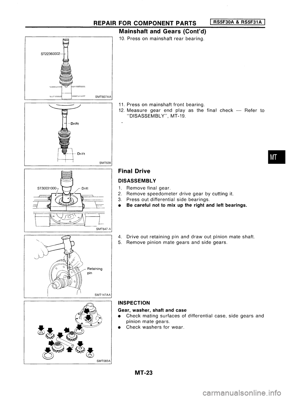
10. Press onmainshaft rearbearing.
SMT607AA
11.Press onmainshaft frontbearing.
12. Measure gearendplayas thefinal check -Refer to
"DISASSEM BL
y",
MT-19.
SMT639 FinalDrive
DISASSEMBL Y
1. Remove finalgear.
2. Remove speedometer drivegearbycutting it.
3. Press outdifferential sidebearings.
• Becareful nottomix upthe right andleftbearings.
•
[ .
SMT647-A
4.Drive outretaining pinand draw outpinion mateshaft.
5. Remove pinionmategears andside gears.
Retaining
pin
SMT147AA INSPECTION
Gear, washer, shaftandcase
• Check mating surfaces ofdifferential case,sidegears and
pinion mategears.
• Check washers forwear.
SMT083A MT-23
Page 1566 of 1701
KV38105900
REPAIR
FORCOMPONENT PARTS
I
RS5F30A
&
RS5F31A
I
Final Drive (Conl'd)
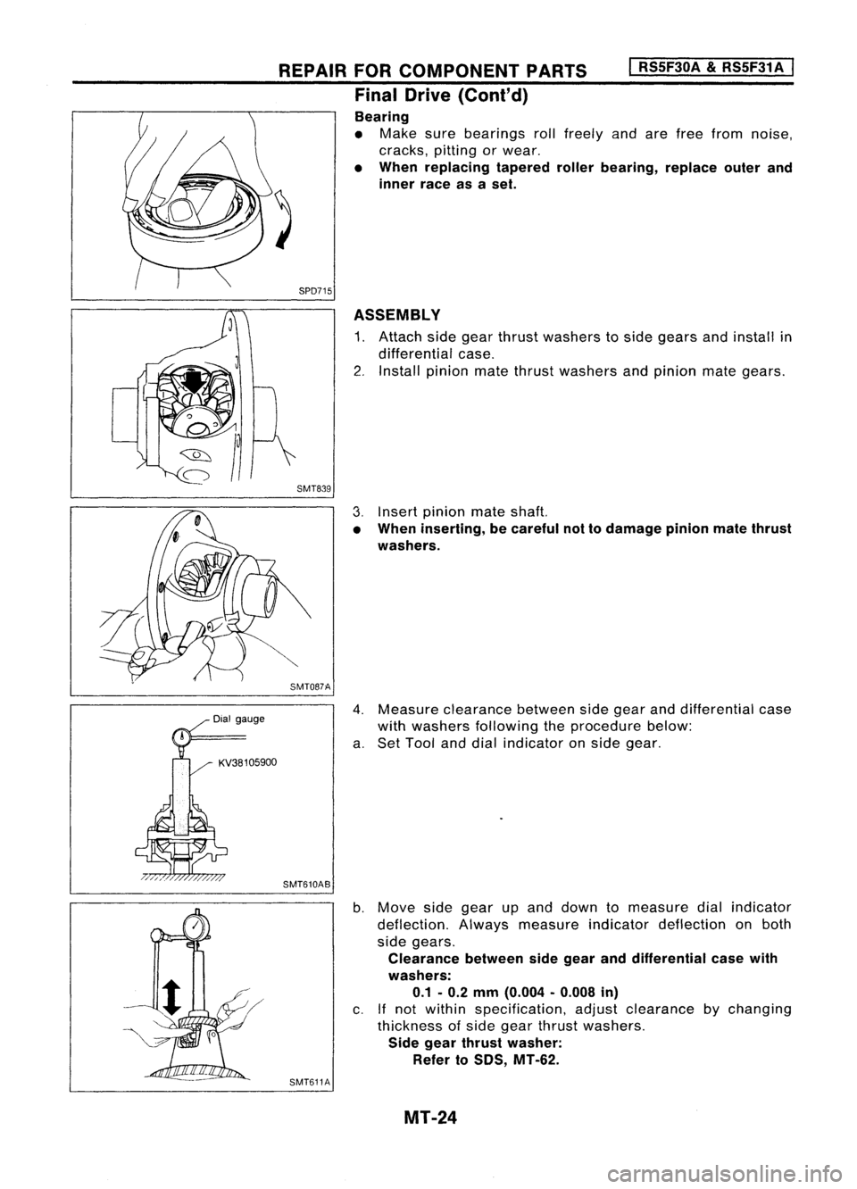
Bearing
• Make surebearings rollfreely andarefree from noise,
cracks, pittingorwear.
• When replacing taperedrollerbearing, replaceouterand
inner raceasaset.
SPD715 ASSEMBLY
1. Attach sidegear thrust washers toside gears andinstall in
differential case.
2. Install pinion matethrust washers andpinion mategears.
SMT839
3.Insert pinion mateshaft.
• When inserting, becareful nottodamage pinionmatethrust
washers.
SMT087A
4.Measure clearance betweensidegear anddifferential case
with washers following theprocedure below:
a. Set Tool anddial indicator onside gear.
SMT610AB
b.Move sidegear upand down tomeasure dialindicator
deflection. Alwaysmeasure indicatordeflection onboth
side gears.
Clearance betweensidegear anddifferential casewith
washers: 0.1 -0.2 mm (0.004 -0.008 in)
c. Ifnot within specification, adjustclearance bychanging
thickness ofside gear thrust washers.
Side gear thrust washer:
Refer to50S, MT-62.
SMT611A
MT-24