glass NISSAN ALMERA N15 1995 Service Manual
[x] Cancel search | Manufacturer: NISSAN, Model Year: 1995, Model line: ALMERA N15, Model: NISSAN ALMERA N15 1995Pages: 1701, PDF Size: 82.27 MB
Page 194 of 1701
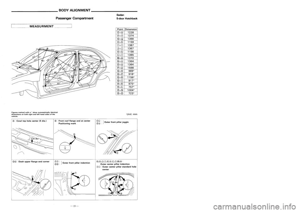
__________ BODYALIGNMENT _
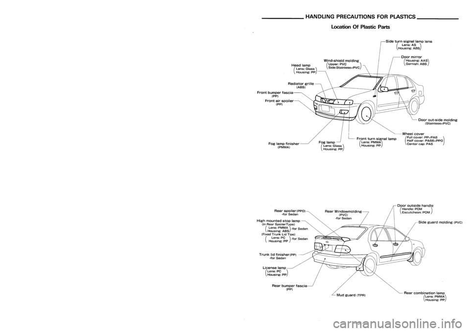
_HANDLINGPRECAUTIONS FORPLASTICS _
Passenger Compartment Sedan
5-door Hatchback Location
OfPlastic Parts
Side turnsignal lamplens
(Lens: AS)
Housing: ASS
Wind-shield molding
(Upper: PVC )
Side:Stainless+PVC
Doorout-side molding
(Stainless+PVC)
Wheel cover
(Full cover: PP+PA6 )
Half cover: PA66+PPO
Center cap:PA6
Door
mirror
(Housing: AAS)
Garnish: ASS
Front turnsignal lamp
(Lens: PMMA)
Housing: PP
Fog
lamp
(Lens: Glass)
Housing: PP
Head
lamp
(Lens: Glass)
Housing: pp
Radiator grille
(ABS)
Fog lamp finisher
(PM MA)
Front
bumper fascia
(PP)
Front airspoiler
(PP)
Point
Dimension
@-@
1228
CB-
@-@
1366
(8)-{6)
1159
CD--cD
1387
Q)-{J) 1367
@--@
1156
(b)--{[)
1385
~-4iV
1370
@~
1364
@~
1364
C'e)--@
1598
@--@
989*
@-{E)
918*
@~
1156*
@--{[)
917*
@~@
975*
@~(b)
757*
@~
1004*
@--@
723*
,
... ._MEASURMENT _
Figures marked witha
*
show symmetrically identical
dimensions onboth right andlefthand sides ofthe
vehicle.
Unit:
mm
@ :
Cowl tophole center (5dia.)
CB>
:
Front roofflange endatcenter
Positioning mark ~~
~}Outer frontpillarjoggle
Sideguard molding (PVC)
Rear combination lamp
(Lens: PMMA)
Housing: PP
Door
outside handle
(Handle: POM )
Escutcheon: POM
Mud guard (TPR)
Rear
Windowmolding
(PVC)
-for Sedan
Rear bumper fascia
(PP)
License
lamp
(Lens: PC)
Housing: PP
Trunk
lidfinisher(pp)
-for Sedan
Rear
spoiler(PPO)
-for Sedan
High mounted stoplamp
(In Rear SpoilerType)
(Lens: PMMA)-for Sedan
Housing: ASS
(Fixed Trunk LidTipe)
(Lens: PC)-for Sedan
Housing: PP
(f3),Cfi),Q),CD,@,@,CD,CD,~,@ :
Outer center pillarindention
CDCD :
Outer center pillarstandard hole
center
CBCD:
}
~@:
Outerfrontpillar indention
@@
:
Dash upper flange endcorner
-19- -26-
Page 201 of 1701
__________ BODYALIGNMENT _
_HANDLINGPRECAUTIONS FORPLASTICS _
Passenger Compartment Sedan
5-door Hatchback Location
OfPlastic Parts
Side turnsignal lamplens
(Lens: AS)
Housing: ASS
Wind-shield molding
(Upper: PVC )
Side:Stainless+PVC
Doorout-side molding
(Stainless+PVC)
Wheel cover
(Full cover: PP+PA6 )
Half cover: PA66+PPO
Center cap:PA6
Door
mirror
(Housing: AAS)
Garnish: ASS
Front turnsignal lamp
(Lens: PMMA)
Housing: PP
Fog
lamp
(Lens: Glass)
Housing: PP
Head
lamp
(Lens: Glass)
Housing: pp
Radiator grille
(ABS)
Fog lamp finisher
(PM MA)
Front
bumper fascia
(PP)
Front airspoiler
(PP)
Point
Dimension
@-@
1228
CB-
@-@
1366
(8)-{6)
1159
CD--cD
1387
Q)-{J) 1367
@--@
1156
(b)--{[)
1385
~-4iV
1370
@~
1364
@~
1364
C'e)--@
1598
@--@
989*
@-{E)
918*
@~
1156*
@--{[)
917*
@~@
975*
@~(b)
757*
@~
1004*
@--@
723*
,
... ._MEASURMENT _
Figures marked witha
*
show symmetrically identical
dimensions onboth right andlefthand sides ofthe
vehicle.
Unit:
mm
@ :
Cowl tophole center (5dia.)
CB>
:
Front roofflange endatcenter
Positioning mark ~~
~}Outer frontpillarjoggle
Sideguard molding (PVC)
Rear combination lamp
(Lens: PMMA)
Housing: PP
Door
outside handle
(Handle: POM )
Escutcheon: POM
Mud guard (TPR)
Rear
Windowmolding
(PVC)
-for Sedan
Rear bumper fascia
(PP)
License
lamp
(Lens: PC)
Housing: PP
Trunk
lidfinisher(pp)
-for Sedan
Rear
spoiler(PPO)
-for Sedan
High mounted stoplamp
(In Rear SpoilerType)
(Lens: PMMA)-for Sedan
Housing: ASS
(Fixed Trunk LidTipe)
(Lens: PC)-for Sedan
Housing: PP
(f3),Cfi),Q),CD,@,@,CD,CD,~,@ :
Outer center pillarindention
CDCD :
Outer center pillarstandard hole
center
CBCD:
}
~@:
Outerfrontpillar indention
@@
:
Dash upper flange endcorner
-19- -26-
Page 249 of 1701
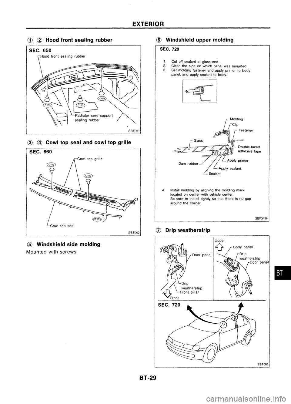
EXTERIOR
CD ~
Hood frontsealing rubber
SEC. 650
CID
Windshield uppermolding
SEC. 720
@lJ
SBF342H
(ID
@
Cowl topseal andcowl topgrille
SEC. 660
1
Cutoffsealant atglass end.
2. Clean theside onwhich panelwasmounted.
3. Setmolding fastener andapply primer tobody
panel, andapply sealant tobody.
4. Install molding byaligning themolding mark
located oncenter withvehicle center.
Be sure toinstall tightly sothat there isno gap
around thecorner.
(f)
Drip weatherstrip
58T061
58T062
Cowl
topseal
Hood
frontsealing rubber
CID
Windshield sidemolding
Mounted with
screws,
SEC.720
Door
panel
SBT063
•
8T-29
Page 260 of 1701

SUNROOF
REMOVAL
• After anyadjustment, checksunroof operation andlidalignment.
• Handle finisher plateandglass lidwith care sonot tocause damage.
• Itis desirable foreasy installation tomark eachpoint before removal.
CAUTION:
Always workwithahelper.
Link andwire
assembly Sunroof
frame
assembly Shade
assembly
~
~
8T-40
Lid
assembly Motorassembly
Page 263 of 1701
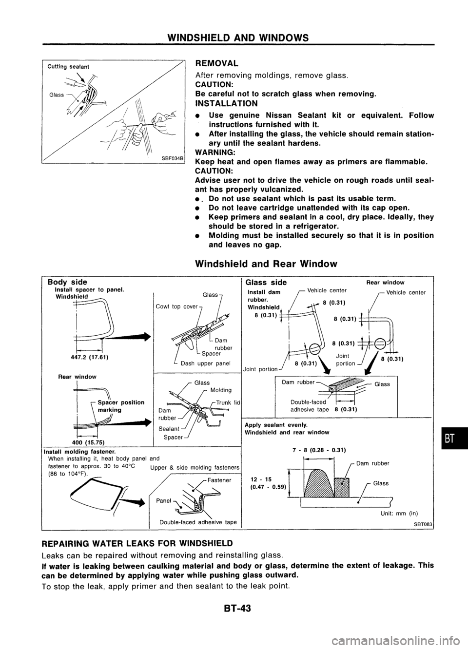
WINDSHIELDANDWINDOWS
Cutting sealant
SBF034BREMOVAL
After removing moldings, removeglass,
CAUTION: Be careful nottoscratch glasswhen removing.
INSTALLATION
• Use genuine NissanSealant kitorequivalent. Follow
instructions furnishedwithit.
• After installing theglass, thevehicle shouldremain station-
ary until thesealant hardens.
WARNING: Keep heatandopen flames awayasprimers areflammable.
CAUTION:
Advise usernottodrive thevehicle onrough roadsuntilseal-
ant has properly vulcanized.
•. Donot use sealant whichispast itsusable term.
• Donot leave cartridge unattended withitscap open.
• Keep primers andsealant inacool, dryplace. Ideally, they
should bestored inarefrigerator.
• Molding mustbeinstalled securely sothat itis in position
and leaves nogap.
Windshield andRear Window
•
Rear
window
Vehicle center
8 (0.31)
Glass
side
Install dam
rubber.
Windshield
8(0.31)
12 -15
(0.47 -0.59)
Apply
sealant evenly.
Windshield andrear window
7 •8 (0.28 •0.31)
Unit:mm(in)
S8T083
fj
'@8(0.31)1:@
Joint8(0.31)
8 (0.31)\ portion
(J
Joint portion "
O,m ,"bb"~
G,,,,
Double-laced
adhesive tape8(0.31)
V
Fastener
P'""~
Double-laced
adhesive
tape
•
Body
side
Install spacer topanel.
Windshield
447.2 (17.61)
Rear window
t==\
h¥:~'
po"II"
markmg
•
400 (15.75)
Install molding fastener.
When installing it,heat body panel and
fastener toapprox. 30to40°C Upper
&
side molding lasteners
(86 to104°F).
0;-.
REPAIRING WATERLEAKSFORWINDSHIELD
Leaks canberepaired withoutremoving andreinstalling glass.
If water isleaking between caulking materialandbody orglass, determine theextent ofleakage. This
can bedetermined byapplying waterwhilepushing glassoutward.
To stop theleak, apply primer andthen sealant tothe leak point.
81-43
Page 447 of 1701
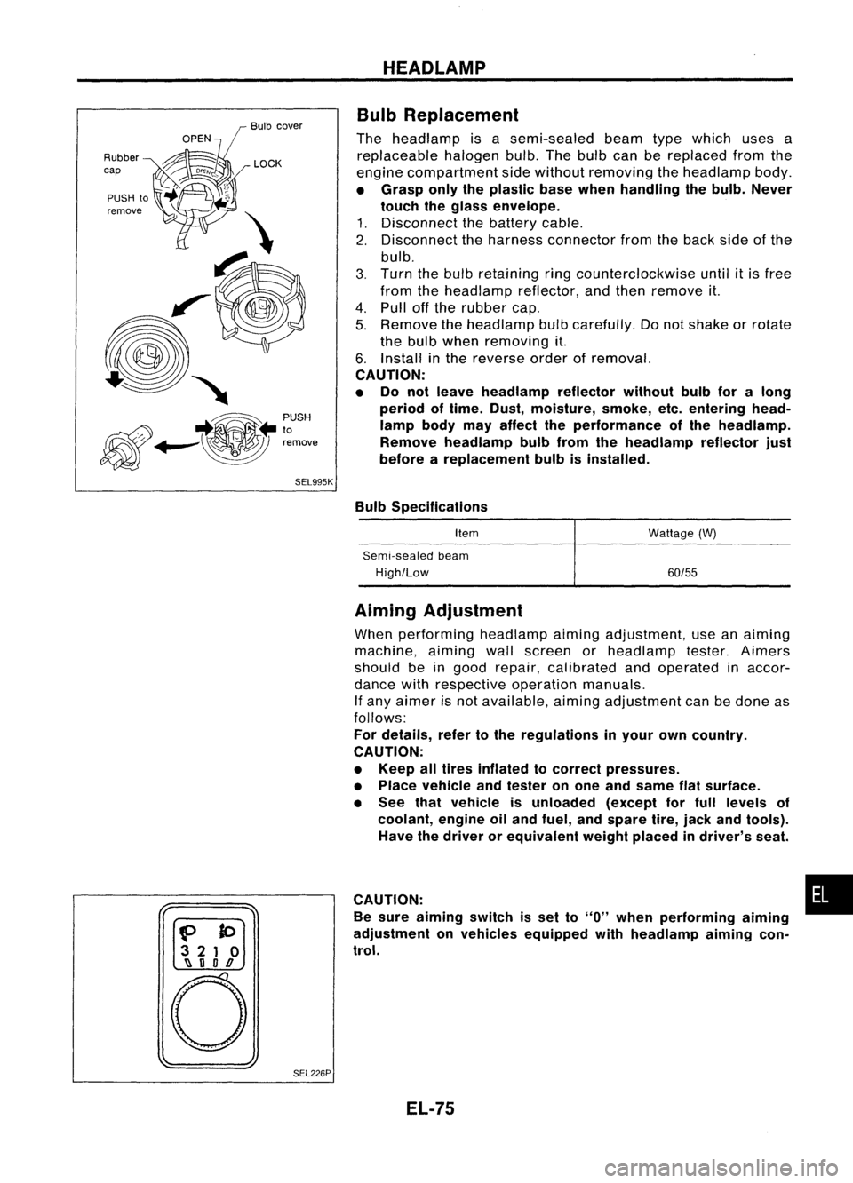
Bulbcover
SEL995K HEADLAMP
Bulb Replacement
The headlamp isasemi-sealed beamtypewhich usesa
replaceable halogenbulb.Thebulb canbereplaced fromthe
engine compartment sidewithout removing theheadlamp body.
• Grasp onlytheplastic basewhen handling thebulb. Never
touch theglass envelope.
1. Disconnect thebattery cable.
2. Disconnect theharness connector fromtheback sideofthe
bulb.
3. Turn thebulb retaining ringcounterclockwise until
it
is free
from theheadlamp reflector,andthen remove it.
4. Pull offthe rubber cap.
5. Remove theheadlamp bulbcarefully. Donot shake orrotate
the bulb when removing it.
6. Install inthe reverse orderofremoval.
CAUTION:
• Do not leave headlamp reflector withoutbulbforalong
period oftime. Dust,moisture, smoke,etc.entering head-
lamp bodymayaffect theperformance ofthe head lamp.
Remove headlamp bulbfrom thehead lamp reflector just
before areplacement bulbisinstalled.
Bulb Specifications
Item
Semi-sealed beam
High/Low Wattage
(W)
60/55
f>
to
3 21 0
~ nOD
o
SEL226PAiming
Adjustment
When performing headlamp aiming adjustment, useanaiming
machine, aimingwallscreen orheadlamp tester.Aimers
should beingood repair, calibrated andoperated inaccor-
dance withrespective operationmanuals.
If any aimer isnot available, aimingadjustment canbedone as
follows:
For details, refertothe regulations inyour owncountry.
CAUTION:
• Keep alltires inflated tocorrect pressures.
• Place vehicle andtester onone and same flatsurface.
• See thatvehicle isunloaded (exceptforfull levels of
coolant, engineoiland fuel, andspare tire,jack andtools).
Have thedriver orequivalent weightplaced indriver's seat.
CAUTION: •
Be sure aiming switchisset to
"0"
when performing aiming
adjustment onvehicles equipped withheadlamp aiming con-
trol.
EL-75
Page 473 of 1701
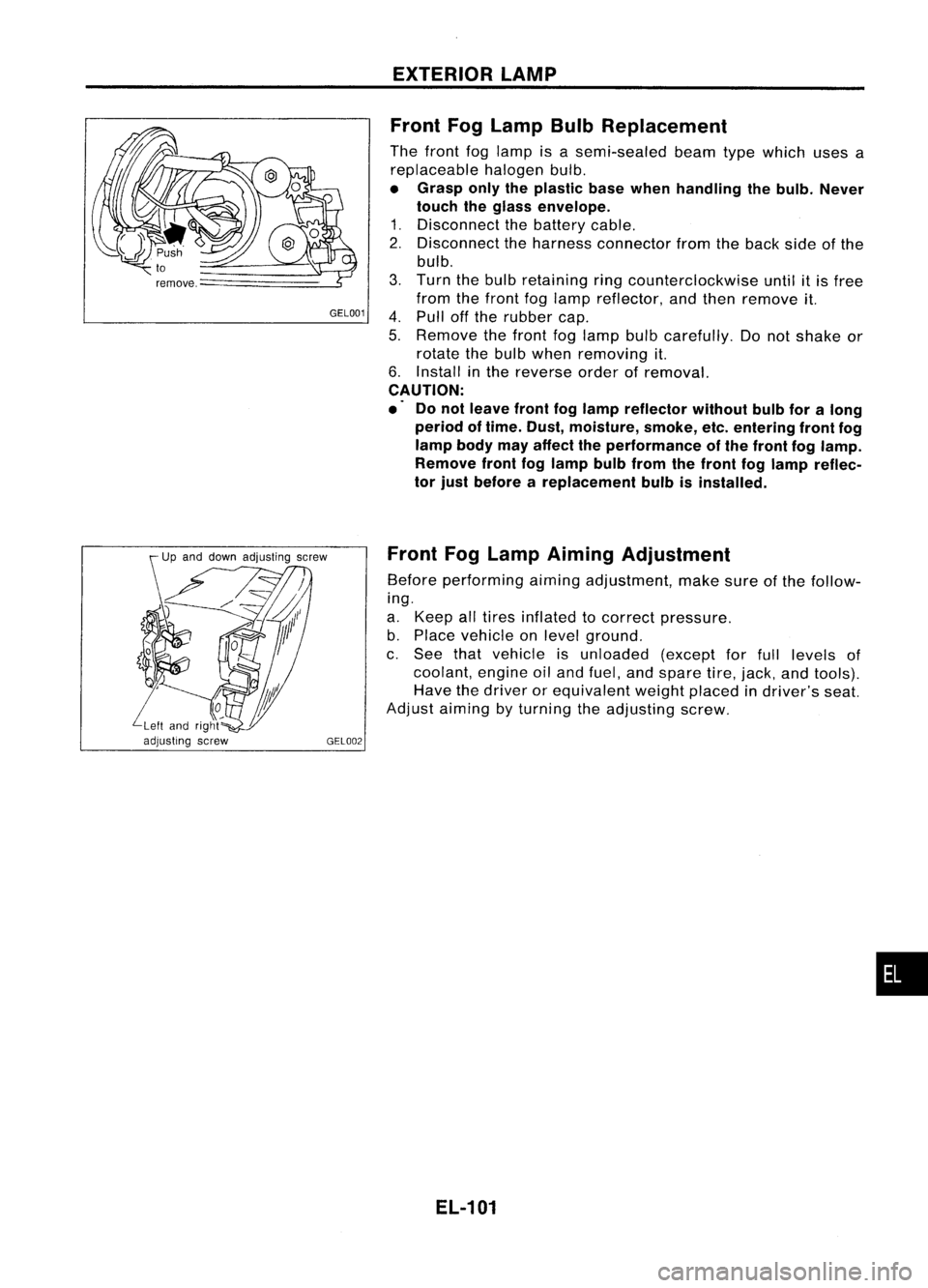
GEL001EXTERIOR
LAMP
Front FogLamp BulbReplacement
The front foglamp isasemi-sealed beamtypewhich usesa
replaceable halogenbulb.
• Grasp onlytheplastic basewhen handling thebulb. Never
touch theglass envelope.
1. Disconnect thebattery cable.
2. Disconnect theharness connector fromtheback sideofthe
bulb.
3. Turn thebulb retaining ringcounterclockwise untilitis free
from thefront foglamp reflector, andthen remove it.
4. Pull offthe rubber cap.
5. Remove thefront foglamp bulbcarefully. Donot shake or
rotate thebulb when removing it.
6. Install inthe reverse orderofremoval.
CAUTION:
.' Donot leave frontfoglamp reflector withoutbulbforalong
period oftime. Dust, moisture, smoke,etc.entering frontfog
lamp bodymayaffect theperformance ofthe front foglamp.
Remove frontfoglamp bulbfrom thefront foglamp reflec-
tor just before areplacement bulbisinstalled.
Front FogLamp Aiming Adjustment
Before performing aimingadjustment, makesureofthe follow-
ing.
a. Keep alltires inflated tocorrect pressure.
b. Place vehicle onlevel ground.
c. See thatvehicle isunloaded (exceptforfull levels of
coolant, engineoiland fuel, andspare tire,jack, andtools).
Have thedriver orequivalent weightplaced indriver's seat.
Adjust aiming byturning theadjusting screw.
EL-101
•
Page 538 of 1701
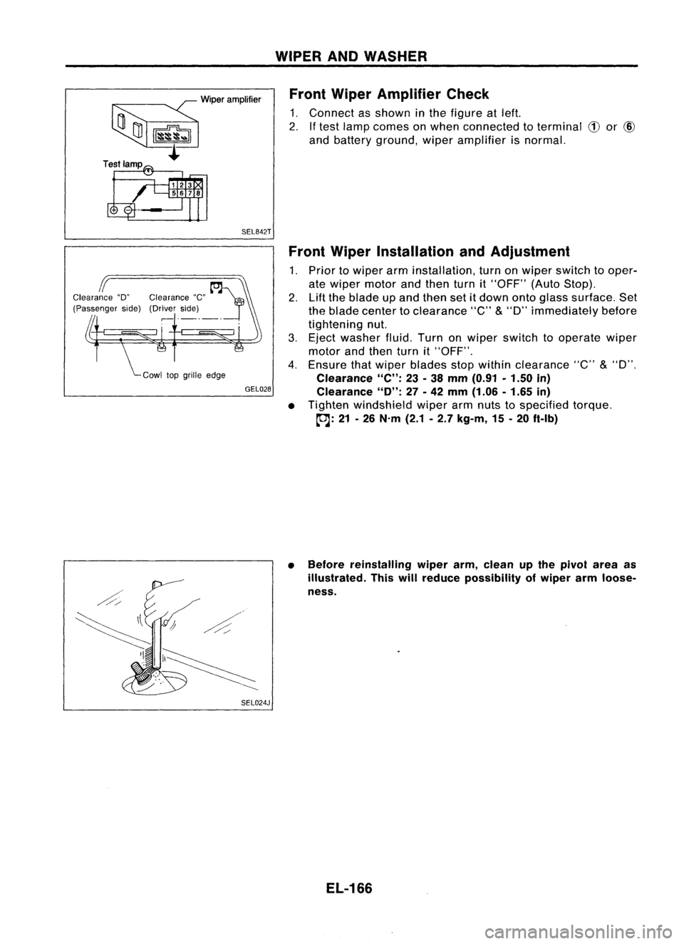
~Wiperamplifier
~~
t
Test lamp
SEL842TWIPER
ANDWASHER
Front Wiper Amplifier Check
1. Connect asshown inthe figure atleft.
2. Iftest lamp comes onwhen connected toterminal
CD
or
@
and battery ground, wiperamplifier isnormal.
GEL028
SEL024J Front
Wiper Installation andAdjustment
1. Prior towiper arminstallation, turnonwiper switch tooper-
ate wiper motor andthen turnit"OFF" (AutoStop).
2. Liftthe blade upand then setitdown ontoglass surface. Set
the blade center toclearance "C"
&
"D" immediately before
tightening nut.
3. Eject washer fluid.Turnonwiper switch tooperate wiper
motor andthen turnit"OFF".
4. Ensure thatwiper blades stopwithin clearance "C"
&
"D".
Clearance
"C":
23-38 mm (0.91 •1.50 in)
Clearance
"0":
27-42 mm (1.06 -1.65 in)
• Tighten windshield wiperarmnuts tospecified torque.
~: 21-26 N'm (2.1-2.7 kg-m, 15-20 ft.lb)
• Before reinstalling wiperarm,clean upthe pivot areaas
illustrated. Thiswillreduce possibility ofwiper armloose-
ness.
EL-166
Page 547 of 1701
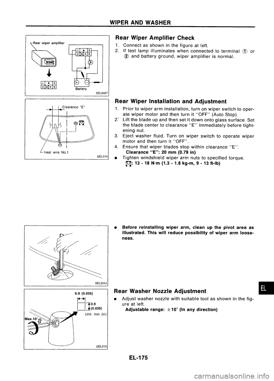
~~:;"f1.'
~
C!E:TIJ
!II8EITJ
SEL846TWIPER
ANDWASHER
Rear Wiper Amplifier Check
1. Connect asshown inthe figure atleft.
2.
If
test lamp illuminates whenconnected toterminal
CD
or
@
and battery ground, wiperamplifier isnormal.
Clearance "E"
GEL014
SEL024J
0.9 (0.035)
~
OJ
O.9
(0.035)
Unit: mm(in)
GEL015 Rear
Wiper Installation andAdjustment
1. Prior towiper arminstallation, turnonwiper switch tooper-
ate wiper motor andthen turnit"OFF" (AutoStop).
2: Liftthe blade upand then setitdown ontoglass surface. Set
the blade center toclearance "E"immediately beforetight-
ening nut.
3. Eject washer fluid.Turnonwiper switch tooperate wiper
motor andthen turnit"OFF".
4. Ensure thatwiper blades stopwithin clearance "E".
Clearance
"E":
20mm (0.79 in)
• Tighten windshield wiperarmnuts tospecified torque.
~: 13-18 N.m (1.3-1.8 kg-m, 9-13 ft-Ib)
• Before reinstalling wiperarm,clean upthe pivot areaas
illustrated. Thiswillreduce possibility ofwiper armloose-
ness.
Rear Washer NozzleAdjustment
• Adjust washer nozzlewithsuitable toolasshown inthe fig-
ure atleft.
Adjustable range:
::l::
10°
(Inany direction)
EL-175
•
Page 608 of 1701
REARWINDOW DEFOGGER ANDDOOR MIRROR DEFOGGER
Filament Repair
REPAIR EQUIPMENT
1. Conductive silvercomposition (DupontNo.4817 orequiva-
lent)
2. Ruler 30cm (11.8 in)long
3. Drawing pen
4. Heat gun
5. Alcohol
6. Cloth
Unit: mm(in)
REPAIRING
PROCEDURE
1. Wipe broken heatwire anditssurrounding areaclean with
a cloth dampened inalcohol.
2. Apply asmall amount ofconductive silvercomposition totip
of drawing pen.
Shake silvercomposition containerbeforeuse.
3. Place ruleronglass along broken line.Deposit conductive
silver composition onbreak withdrawing pen.Slightly over-
lap existing heatwire onboth sides [preferably 5mm (0.20
in)] ofthe break.
4. After repair hasbeen completed, checkrepaired wirefor
continuity. Thischeck should beconducted 10minutes after
silver composition isdeposited.
Do not touch repaired areawhile testisbeing conducted.
BE540
SEL012D
Break
R .d
epalre point
j
IrJ
t..@.!.
-
--
Heat
wire
Repairedpoint
5.
Apply aconstant streamofhot airdirectly tothe repaired
area forapproximately 20minutes withaheat gun.Amini"-
mum distance of3cm (1.2 in)should bekept between
repaired areaandhotairoutlet. Ifa heat gunisnot
available, letthe repaired areadryfor24hours.
SEL013D
EL-236