low beam NISSAN ALMERA N15 1995 Service Manual
[x] Cancel search | Manufacturer: NISSAN, Model Year: 1995, Model line: ALMERA N15, Model: NISSAN ALMERA N15 1995Pages: 1701, PDF Size: 82.27 MB
Page 192 of 1701
(NP130) aremost commonl")
__________ BODYALIGNMENT ___________
PRECAUTIONS _
Underbody Precautions
ForHandling HighStrength Steel
• InNissan vehicles, HSSplates of373 N/mm
2
(38kg/mm
2,
54klb/sq in)(NP130) aremost commonly
utilized, andthose withatensile strength of785 to981 N/mm
2
(80to100 kg/mm
2,
114to142 klb/sq
in) (NP150) areused onlyonparts requiring muchmorestrength.
HIGH
STRENGTH STEEL(HSS)USED INNISSAN VEHICLES
High
strength steelhasbeen usedforbody panels inorder toreduce vehicle weight.
Accordingly, precautionsinrepairing automotive bodiesmadeofhigh strength steelaredescribed below:
Tensile strength Nissan designation Major
applicable parts
• Side member
373N/mm
2
•
Hoodledge
(38 kg/mm
2,
54klb/sq in) NP130
•
Pillar
• Hood
.Trunk lidouter
785-981 N/mm
2
•Bumper reinforcement
(80-100 kg/mm
2
NP150
114-142 klb/sqin) •
Door guard beam
E
E
127
@>@)
235
~200
ee
@@
o
It)
CD
N
.. CD
.. 00
~ N~
It)
CD
CD
It)
C!.
~
CD
It)
It)
en
N
It)
CD CD
IIIlI:t'
(ij
Q)
er:
iJ
--------
en
It)
C!.
N
~ en
co
____
MEASURMENT _
..
o
.. It)
0)
It)
o
I'
..
.. 0
CD CD
en~
0) .,
~
129
@8
@@
@)@)
225
SBT096
-17- -28-
Page 203 of 1701
(NP130) aremost commonl")
__________ BODYALIGNMENT ___________
PRECAUTIONS _
Underbody Precautions
ForHandling HighStrength Steel
• InNissan vehicles, HSSplates of373 N/mm
2
(38kg/mm
2,
54klb/sq in)(NP130) aremost commonly
utilized, andthose withatensile strength of785 to981 N/mm
2
(80to100 kg/mm
2,
114to142 klb/sq
in) (NP150) areused onlyonparts requiring muchmorestrength.
HIGH
STRENGTH STEEL(HSS)USED INNISSAN VEHICLES
High
strength steelhasbeen usedforbody panels inorder toreduce vehicle weight.
Accordingly, precautionsinrepairing automotive bodiesmadeofhigh strength steelaredescribed below:
Tensile strength Nissan designation Major
applicable parts
• Side member
373N/mm
2
•
Hoodledge
(38 kg/mm
2,
54klb/sq in) NP130
•
Pillar
• Hood
.Trunk lidouter
785-981 N/mm
2
•Bumper reinforcement
(80-100 kg/mm
2
NP150
114-142 klb/sqin) •
Door guard beam
E
E
127
@>@)
235
~200
ee
@@
o
It)
CD
N
.. CD
.. 00
~ N~
It)
CD
CD
It)
C!.
~
CD
It)
It)
en
N
It)
CD CD
IIIlI:t'
(ij
Q)
er:
iJ
--------
en
It)
C!.
N
~ en
co
____
MEASURMENT _
..
o
.. It)
0)
It)
o
I'
..
.. 0
CD CD
en~
0) .,
~
129
@8
@@
@)@)
225
SBT096
-17- -28-
Page 393 of 1701
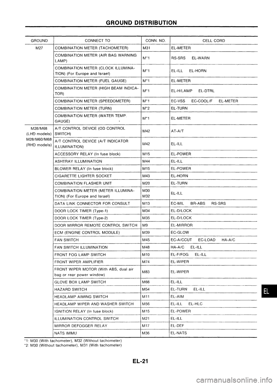
GROUNDDISTRIBUTION
GROUND CONNECT
TO CONN.NO.
CELLCORD
M27 COMBINATION
METER(TACHOMETER) M31EL-METER
COMBINATION METER(AIRBAG WARNING
M'1 RS-SRSEL-WARN
LAMP)
COMBINATION METER(CLOCK ILLUMINA-
M'1 EL-ILL
EL-HORN
TION) (ForEurope andIsrael)
COMBINATION METER(FUELGAUGE) M'1
EL-METER
COMBINATION METER(HIGHBEAM INDICA-
M'1 EL-H/LAMPEL-DTRL
TOR)
COMBINATION METER(SPEEDOMETER) M'1
EC-VSSEC-COOLIF EL-METER
COMBINATION METER(TURN) M'2EL-TURN
COMBINATION METER(WATER TEMP.
M'1 EL-METER
GAUGE)
.
M28/M68
A/T
CONTROL DEVICE(ODCONTROL
(LHD models)
SWITCH) M42
AT-A/T
M28/M60/M68
A/T
CONTROL DEVICE
(A/T
INDICATOR
(RHD models)
ILLUMINATION) M42
EL-ILL
ACCESSORY RELAY(Infuse block) M15
EL-POWER
ASHTRAY ILLUMINATION M44
EL-ILL
BLOWER RELAY(Infuse block) M15
EL-POWER
CIGARETTE LIGHTERSOCKET M43
EL-HORN
COMBINATION FLASHERUNIT M20EL-TURN
COMBINATION METER(METER ILLUMINA- M30
TION) (ForEurope andIsrael) M32EL-ILL
DATA LINKCONNECTOR FORCONSULT M13
EC-MILBR-ABS RS-SRS
DOOR LOCKTIMER (Type-1) M34
EL-D/LOCK
DOOR LOCKTIMER (Type-2) M35EL-D/LOCK
DOOR MIRROR REMOTE CONTROL SWITCHM9 EL-MIRROR
ECM (ENGINE CONTROL MODULE) M39EC-GLOW
FAN SWITCH M45
EC-A/CCUT
EC-LOADHA-A/C
FAN SWITCH ILLUMINATION M48HA-A/C
EL-ILL
FRONT FOGLAMP SWITCH M10EL-F/FOG
EL-ILL
FRONT WIPERAMPLIFIER M74
EL-WIPER
FRONT WIPERMOTOR (WithASS,dualair
M83 EL-WIPER
bag orrear power window)
GLOVE BOXLAMP SWITCH M66EL-ILL
HAZARD SWITCH M54
EL-TURN
EL-ILL
HEADLAMP AIMINGSWITCH M11EL-AIM
HEADLAMP WIPERANDWASHER SWITCH M56 EL-ILL
EL-HLC
IGNITION RELAY(Infuse block) M15EL-POWER
ILLUMINATION CONTROLSWITCH M21
EL-ILL
MIRROR DEFOGGER RELAY M17
EL-DEF
NATS IMMU M36EL-NATS
'1: M30 (With tachometer), M32(Without tachometer)
'2: M30 (Without tachometer), M31(With tachometer)
EL-21
•
Page 439 of 1701

HEADLAMP-.Without Daytime LightSystem -
Trouble Diagnoses
Symptom Possiblecause Repair
order
LH
head lamps donot operate.
1.
Bulb
1.
Check bulb.
2. LH
head lamp ground
2.
Check
LH
headlamp ground.(Terminal
@)
3.
15A fuse
3.
Check
15Afuse (No.
@ill,
located infusible linkand
fuse box).
4.
Lighting switch
4.
Check
lighting switch.
RH headlamps donot operate.
1.
Bulb 1.
Check bulb.
2.
RH head lamp ground
2.
Check
RHhead lamp ground. (Terminal
@)
3
15A
fuse
3.
Check
15Afuse (No.~,located infusible linkand
fuse box).
4.
Lighting
switch
4.
Check lighting switch.
LH
high beam doesnotoperate, 1.Bulb
1. Check
bulb.
.
but
LH
low beam operates.
2.
Open in
LH
high beam circuit
r,
Check RIBwire between lightingswitch
and
LH
L.
head lamp foranopen circuit.
3.
Lighting switch
3.
Check
lighting switch.
LH
low beam doesnotoperate,
1.
Bulb
1.
Check bulb.
but
LH
high beam operates.
2.
Open
in
LH
low beam circuit
2.
Check
R/Ywire between lightingswitchand
LH
headlamp foranopen circuit.
3.
Lighting
switch
3.
Check
lighting switch.
RH high beam doesnotoperate, 1.Bulb. 1.Check
bulb.
but RHlow beam operates.
2.
Open
inRH high beam circuit
2.
Check
RIG
wire between lightingswitch
andRH
headlamp foranopen circuit.
3.
Lighting
switch.
3.
Check
lighting switch.
_.
RH low
beam doesnotoperate,
1.
Bulb 1.
Check bulb.
but RHhigh beam operates.
2.
Open
inRH low beam circuit
2.
Check
P/Lwire between lightingswitchandRH
head lamp foranopen circuit.
3.
Lighting
switch
3.
Check
lighting switch.
High beam indicator
doesnot
1.Bulb 1.Check
bulbincombination meter.
work.
2.
High
beam indicator ground
2.
Check
combination meterground. [Terminal
@
(with tachometer) or
@
(without tachometer)]
3.
Open inhigh beam circuit
3.
Check
RIBwire between lightingswitchandcom-
bination meterforanopen circuit.
EL-67
•
Page 440 of 1701

The headlamps' lowbeam andclearance, license,tailand illu-
mination lampsautomatically turnonafter starting theengine
with lighting s")
HEADLAMP-Daytime LightSystem -
Operation (Daytimelightsystem)
The headlamps' lowbeam andclearance, license,tailand illu-
mination lampsautomatically turnonafter starting theengine
with lighting switchin"OFF" position.
Lighting switchoperations otherthantheabove arethesame
as conventional lightsystems.
Engine With
engine stopped Withengine running
OFF
1ST2ND
OFF
1ST2ND
Lighting switch
B
C
A
B
C
B
C
A
B
C
B
C
A
B
C
A AA
High beam
XX
0
X
X
0
0
X
0
X
X
0
XX
0
0
X
0
Headlamp
0
0
()
0
()
Low beam
X
XX
XX
X
X
X
XXXX X
Clearance andtaillamp
X
XX
0
0
0
0
00
0
0
0
0
00
0
0
0
License andinstrument illumination lamp
X
XX
0 0
0
0
0
0
0
0 00
0
0()
0
0
0: Lamp "ON"
X: Lamp "OFF"
o :
Added functions
EL-68
Page 441 of 1701

HEADLAMP-Daytime LightSystem -
System Description
The headlamp systemonvehicles forNorth Europe contains adaytime lightunit.Theunitactivates the
following whenever theengine isrunning withthelighting switchinthe OFF position:
• Low beam headlamps
• Clearance, license,tailand illumination lamps
Power issupplied atall times
• through 15Afuse (No.
@ill,
located inthe fusible linkand fuse box)
• todaytime lightunitterminal @and
• tolighting switchterminal
@.
Power isalso supplied atall times
• through 15Afuse (No.~,located inthe fusible linkand fuse box)
• todaytime lightunitterminal
CID
and
• tolighting switchterminal
CID.
Power isalso supplied atall times
• through 10Afuse (No.~,located inthe fusible linkand fuse box)
• todaytime lightunitterminal
CD
and
• tolighting switchterminal @.
With theignition switchinthe ONorSTART position, powerissupplied
• through 10Afuse (No.~,located inthe fuse block)
• todaytime lightunitterminal (]).
With theignition switchinthe START position, powerissupplied
• through 7.5Afuse(No.
l2~,
located inthe fuse block)
• todaytime lightunitterminal @.
Ground issupplied todaytime lightunitterminal @through bodygrounds
@
and@D.
HEADLAMP OPERATION (Daytimelightcancel operation)
Power issupplied atall times
• through 10Afuse (No.~,located inthe fuse andfusible linkbox)
• tolighting switchterminal
@.
When thelighting switchisturned tothe 1stor2nd position
• through lightingswitchterminal @,
• todaytime lightunitterminal
@.
Then daytime lightwillbecanceled. Andthelighting systemoperation willbethe same asnodaytime
light system.
DAYTIME LIGHTOPERATION
With theengine running andthelighting switchinthe OFF position, powerissupplied
• from alternator terminal
CI>
• todaytime lightunitterminal
@
• todaytime lightunitterminal @
• through daytime lightunitterminal
CID
• toterminal
@)
ofLH headlamp
• todaytime lightunitterminal
CID
• through daytime lightunitterminal @
• toterminal
@)
ofRH headlamp
• todaytime lightunitterminal
CD
• through daytime lightunitterminal
@)
• totail lamp andillumination.
Ground issupplied toterminal
@
ofeach headlamp throughbodygrounds
@
and@D.
Ground isalso supplied toterminal @ofdaytime lightunitthrough bodygrounds
@
and@D.
EL-69
•
Page 442 of 1701

HEADlAMP-Daytime lightSystem -
Schematic
HEADLAMPRH
High
Low
HIGH BEAM
INDICATOR
HEADLAMP LH
High
Low
ill
UJ
..,;
'J
Ul
0
::J
..,;
..,;
.c
LL
WO
(fl .....
C+'
w
ill
.
.-1.rl
UJ
,...,E
>-
::J
.::J
IT
LL
W"'"
ill
u.-.
I-
c.....
I-
<0
« I-LD
m
ill
H
UJ Z
w
::J ::J
,...,
(fl
LL
u,...,
0.
l-
.....
E
I OlUlU
(9
I-+,"'"
I H
U --l
I-
IJJ
IJJ
H UJ
::E
3:
::J
UJ
LL
H
I-
Z
>-
0
«
H
0
1-1-
HIT
Z«
(91-
HUJ IJJ
UJ
::J
LL
01
I
aJ
U
I-
ill
H UJ IT
3:1-
::J
0
UJIT
LL
I-
« «
ZI- Z
OUJ IT
H (9 IJJ
I-L
I-
HO IJJZ
--l
Z (9H
«
(9Z ITZCL
HO «IT::E
I««
U3:--l
El-70
HEL015
Page 445 of 1701

EL-DTRL-03
•
HIGH
HEADLAMP
LH
LOW
m
HIGH HEADLAMP
RH
LOW ~
Refer tolast page
(Foldout page).
DAYTIME
LIGHT
UNIT
(ffiID
RI")
HEADLAMP-Daytime LightSystem -
Wiring Diagram -DTRL -(Cont'd)
EL-DTRL-03
•
HIGH
HEADLAMP
LH
LOW
m
HIGH HEADLAMP
RH
LOW ~
Refer tolast page
(Foldout page).
DAYTIME
LIGHT
UNIT
(ffiID
RIB
!(J
BQ
R/Y
JD
RIG
!(J
sQ
PIL
JD
@:
With tachometer
@:
Without tachometer
*3"'@ 14
@
38
,
*4"'@15 @37
,
~(ffiID
~GY
TAIL
LAMP
OUTPUT
~
RIB
~ Toclearance. license.tail
and illumination lamps
GND
~ B
,..,
B S
~ ~
@~
,..,
B B
~ ~
(M28) ~
.
-.
-
-
-
-
I
.-
-
-
-
RIB
1r$J1~
@
RIB
I it"S INATION
METER
(HIGH BEAM
INDICATOR)
1*':' ~
B
@
W
.-
JOINT
CONNECTOR-1
1bjJ~
B
I
~
R/Y
<&
RIG
~ PIL
Preceding
page
~~m
[]]JgJ]
B'8
I1IillIillIITil
~
~ SR
HEL018
EL-73
Page 447 of 1701

Bulbcover
SEL995K HEADLAMP
Bulb Replacement
The headlamp isasemi-sealed beamtypewhich usesa
replaceable halogenbulb.Thebulb canbereplaced fromthe
engine compartment sidewithout removing theheadlamp body.
• Grasp onlytheplastic basewhen handling thebulb. Never
touch theglass envelope.
1. Disconnect thebattery cable.
2. Disconnect theharness connector fromtheback sideofthe
bulb.
3. Turn thebulb retaining ringcounterclockwise until
it
is free
from theheadlamp reflector,andthen remove it.
4. Pull offthe rubber cap.
5. Remove theheadlamp bulbcarefully. Donot shake orrotate
the bulb when removing it.
6. Install inthe reverse orderofremoval.
CAUTION:
• Do not leave headlamp reflector withoutbulbforalong
period oftime. Dust,moisture, smoke,etc.entering head-
lamp bodymayaffect theperformance ofthe head lamp.
Remove headlamp bulbfrom thehead lamp reflector just
before areplacement bulbisinstalled.
Bulb Specifications
Item
Semi-sealed beam
High/Low Wattage
(W)
60/55
f>
to
3 21 0
~ nOD
o
SEL226PAiming
Adjustment
When performing headlamp aiming adjustment, useanaiming
machine, aimingwallscreen orheadlamp tester.Aimers
should beingood repair, calibrated andoperated inaccor-
dance withrespective operationmanuals.
If any aimer isnot available, aimingadjustment canbedone as
follows:
For details, refertothe regulations inyour owncountry.
CAUTION:
• Keep alltires inflated tocorrect pressures.
• Place vehicle andtester onone and same flatsurface.
• See thatvehicle isunloaded (exceptforfull levels of
coolant, engineoiland fuel, andspare tire,jack andtools).
Have thedriver orequivalent weightplaced indriver's seat.
CAUTION: •
Be sure aiming switchisset to
"0"
when performing aiming
adjustment onvehicles equipped withheadlamp aiming con-
trol.
EL-75
Page 448 of 1701

LOW BEAM
1. Turn headlamp lowbeam on.
2. Use adjusting screwstoperform aimingadjustment.
• First tighten th")
-
Up and down adjusting screw
, \ ,I/
MEL614DHEADLAMP
Aiming Adjustment (Cont'd)
LOW BEAM
1. Turn headlamp lowbeam on.
2. Use adjusting screwstoperform aimingadjustment.
• First tighten theadjusting screwallthe way andthen make
adjustment byloosening thescrew.
• Adjust headlamps sothat main axisoflight isparallel to
center lineofbody andisaligned withpoint Pshown in
illustration.
• Figure tothe leftshows headlamp aiming pattern fordriv-
ing onright sideofroad; fordriving onleft side ofroad,
aiming pattern isreversed.
• Dotted linesinillustration showcenter ofhead lamp.
"H":
Horizontal centerlineofheadlamps
"W
L":
Distance betweeneachheadlamp center
"l":
5,000mm(196.85 in)
"e":
65mm (2.56 in)
Height of
lamp centers
I
f
P \
/~
Vertical
centerline
ahead ofheadlamps -
"H":
Horizontal
center line
of headlamps
d
=
ACCEPTABLE RANGE
SEL2541
EL-76