oil NISSAN ALMERA N15 1995 Service Manual
[x] Cancel search | Manufacturer: NISSAN, Model Year: 1995, Model line: ALMERA N15, Model: NISSAN ALMERA N15 1995Pages: 1701, PDF Size: 82.27 MB
Page 1 of 1701
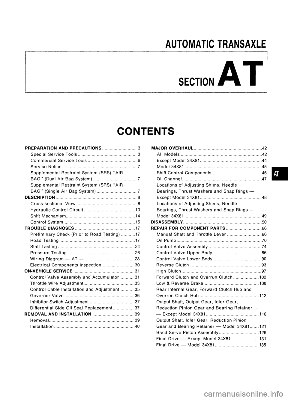
AUTOMATICTRANSAXLE
SECTION
AT
CONTENTS
PREPARATION ANDPRECAUTIONS
3
Special Service Tools 3
Commercial ServiceTools 6
Service Notice 7
Supplemental RestraintSystem(SRS)"AIR
BAG" (DualAirBag System) 7
Supplemental RestraintSystem(SRS)"AIR
BAG" (Single AirBag System) 7
DESCRIPTION
8
Cross-sectional View 8
Hydraulic ControlCircuit 10
Shift Mechanism 14
Control System 15
TROUBLE DIAGNOSES 17
Preliminary Check(PriortoRoad Testing) 17
Road Testing 17
Stall Tasting 24
Pressure Testing 26
Wiring Diagram -AT - 28
Electrical Components Inspection 30
ON-VEHICLE SERVICE 31
Control ValveAssembly andAccumulator 31
Throttle WireAdjustment.. 33
Control CableInstallation andAdjustment 35
Governor Valve 36
Inhibitor SwitchAdjustment 37
Differential SideOilSeal Replacement.. 37
REMOVAL ANDINSTALLATION
39
Removal 39
Installation .40MAJOR
OVERHAUL.. 42
All Models 42
Except Model34X81 .44
Model 34X81 45•
Shift Control Components 46
i
Oil Channel 47
Locations ofAdjusting Shims,Needle
Bearings, ThrustWashers andSnap Rings -
Except Model34X81 .48
Locations ofAdjusting Shims,Needle
Bearings, ThrustWashers andSnap Rings -
Model 34X81 .49
DiSASSEMBLy 50
REPAIR FORCOMPONENT PARTS 66
Manual ShaftandThrottle Lever 66
Oil Pump 70
Control ValveAssembly 74
Control ValveUpper Body 86
Control ValveLower Body 90
Reverse Clutch 93
High Clutch 97
Forward ClutchandOverrun Clutch 102
Low &Reverse Brake 108
Rear Internal Gear,Forward ClutchHuband
Overrun ClutchHub 112
Output Shaft,Output Gear,IdlerGear,
Reduction PinionGearandBearing Retainer
- Except Model34X81 116
Output Shaft,IdlerGear, Reduction Pinion
Gear andBearing Retainer -Model 34X81 121
Band Servo Piston Assembly 126
Final Drive -Except Model34X81 131
Final Drive -Model 34X81 135
Page 3 of 1701
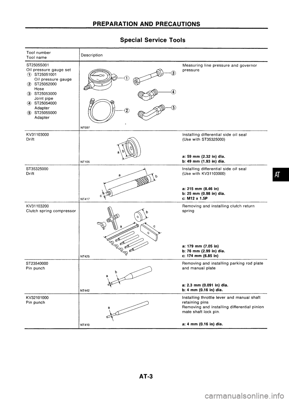
Toolnumber
Tool name
PREPARATION
ANDPRECAUTIONS
Special Service Tools
Description
8T25058001
Oil pressure gaugeset
G)
8T25051001
Oil pressure gauge
@ 8T25052000
Hose
@
8T25053000
Joint pipe
@
8T25054000
Adapter
@
8T25055000
Adapter Measuring
linepressure andgovernor
pressure
NT097
KV31103000
Drift
8T35325000 Drift
KV31103200
Clutch spring compressor
8T23540000 Pin punch
KV32101000
Pin punch
NT105
NT417
NT425
NT442
NT410
AT-3
Installing
differential sideoilseal
(Use with8T35325000)
a: 59 mm (2.32 in)dia.
b: 49 mm (1.93 in)dia.
Installing differential sideoilseal
(Use withKV31103000)
a: 215 mm (8.46 in)
b: 25 mm (0.98 in)dia.
c: M12 x1.5P
Removing andinstalling clutchreturn
spring
a: 179 mm (7.05 in)
b: 76 mm (2.99 in)dia.
c: 174 mm (6.85 in)
Removing andinstalling parkingrodplate
and manual plate
a: 2.3 mm (0.091 in)dia.
b: 4mm (0.16 in)dia.
Installing throttleleverandmanual shaft
retaining pins
Removing andinstalling differential pinion
mate shaft lockpin.
a: 4mm (0.16 in)dia.
•
Page 4 of 1701
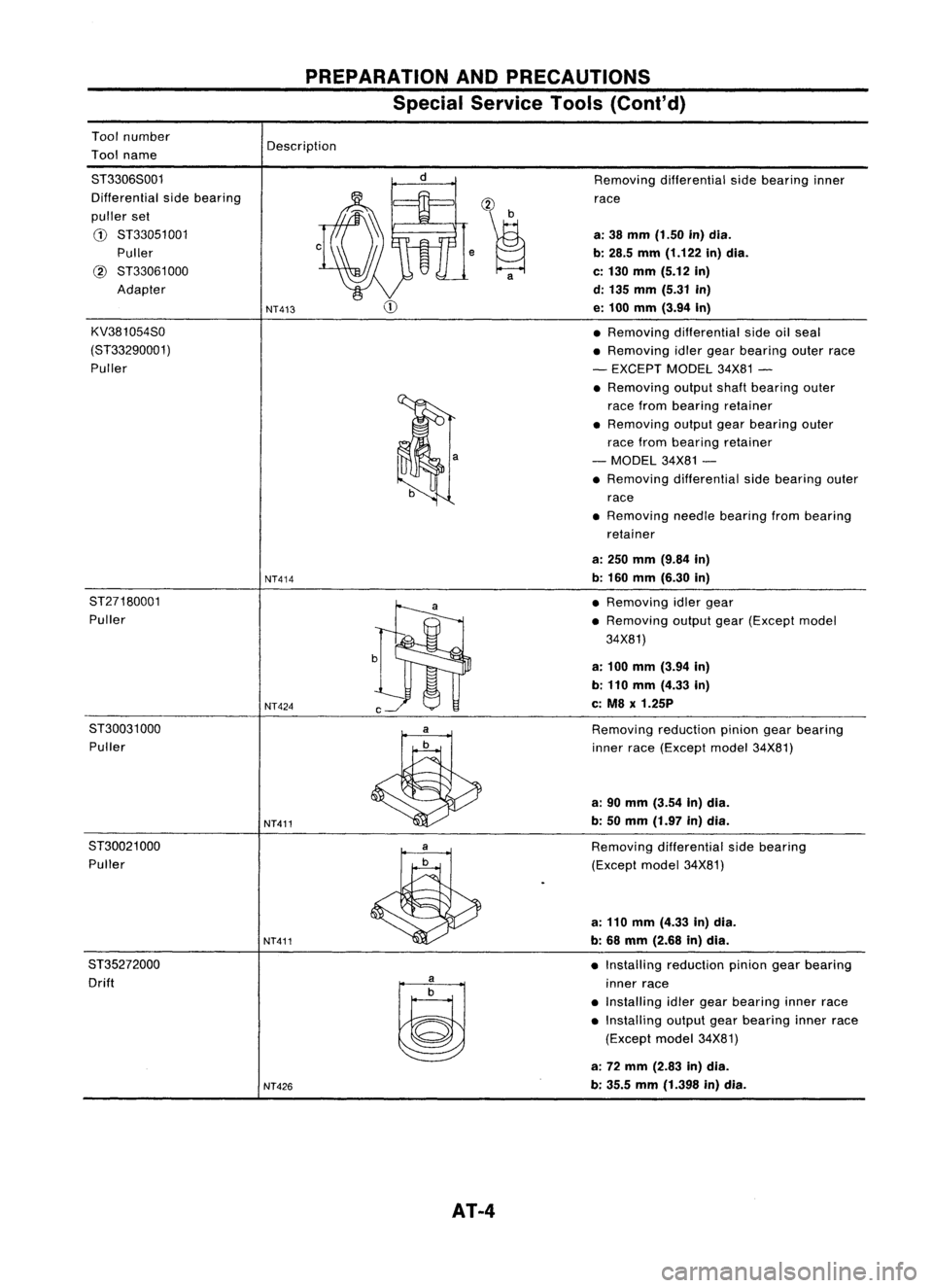
Toolnumber
Tool name
PREPARATION
ANDPRECAUTIONS
Special Service Tools(Cont'd)
Description
ST3306S001
Differential sidebearing
puller set
CD
ST33051 001
Puller
@
ST33061000
Adapter
KV381054S0
(ST33290001) Puller
NT413
NT414 ,~
a
Removing
differential sidebearing inner
race
a: 38 mm (1.50 in)dia.
b: 28.5 mm(1.122 in)dia.
c: 130 mm (5.12 in)
d: 135 mm (5.31 in)
e: 100 mm (3.94 In)
• Removing differential sideoilseal
• Removing idlergear bearing outerrace
- EXCEPT MODEL34X81-
• Removing outputshaftbearing outer
race from bearing retainer
• Removing outputgearbearing outer
race from bearing retainer
- MODEL 34X81-
• Removing differential sidebearing outer
race
• Removing needlebearing frombearing
retainer
a: 250 mm (9.84 in)
b: 160 mm (6.30 in)
ST27180001 Puller
NT424
ST30031000 Puller
NT411
ST30021 000
Puller
NT411
ST35272000 Drift
~
NT426
AT-4
•
Removing idlergear
• Removing outputgear(Except model
34X81)
a: 100 mm (3.94 In)
b: 110 mm (4.33 in)
c: M8 x1.25P
Removing reductionpiniongearbearing
inner race(Except model34X81)
a: 90 mm (3.54 In)dia.
b: 50 mm (1.97 in)dia.
Removing differential sidebearing
(Except model34X81)
a: 110 mm (4.33 in)dia.
b: 68 mm (2.68 in)dia.
• Installing reduction piniongearbearing
inner race
• Installing idlergear bearing innerrace
• Installing outputgearbearing innerrace
(Except model34X81)
a: 72 mm (2.83 in)dia.
b: 35.5 mm(1.398 in)dia.
Page 5 of 1701
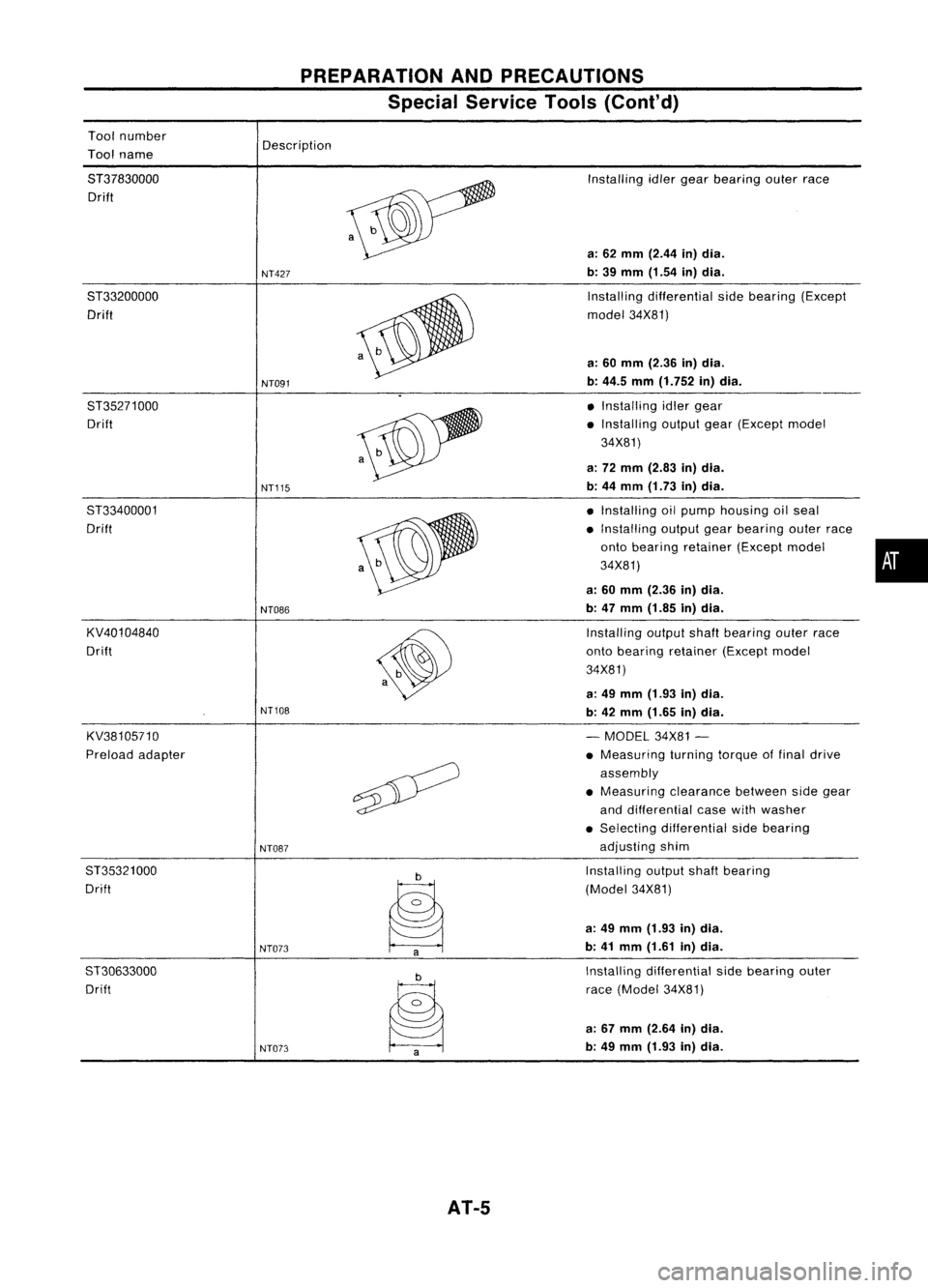
Toolnumber
Tool name
PREPARATION
ANDPRECAUTIONS
Special Service Tools(Cont'd)
Description
8T37830000 Drift
8T33200000 Drift
8T35271000 Drift
8T33400001
Drift
KV40104840
Drift
KV38105710
Preload adapter
8T35321000
Drift
ST30633000 Drift
NT427
NT091
NT115
NT086
NT108
NT087
NT073 NT073
AT-5
Installing
idlergear bearing outerrace
a: 62 mm (2.44 in)dia.
b: 39 mm (1.54 in)dia.
Installing differential sidebearing (Except
model 34X81)
a: 60 mm (2.36 in)dia.
b: 44.5 mm(1.752 in)dia.
• Installing idlergear
• Installing outputgear(Except model
34X81)
a: 72 mm (2.83 in)dia.
b: 44 mm (1.73 in)dia.
• Installing oilpump housing oilseal
• Installing outputgearbearing outerrace
onto bearing retainer (Exceptmodel •
34X81)
a: 60 mm (2.36 in)dia.
b: 47 mm (1.85 in)dia.
Installing outputshaftbearing outerrace
onto bearing retainer (Exceptmodel
34X81)
a: 49 mm (1.93 in)dia.
b: 42 mm (1.65 in)dia.
- MODEL 34X81-
• Measuring turningtorqueoffinal drive
assembly
• Measuring clearancebetweensidegear
and differential casewithwasher
• Selecting differential sidebearing
adjusting shim
Installing outputshaftbearing
(Model 34X81)
a: 49 mm (1.93 in)dia.
b: 41 mm (1.61 in)dia.
Installing differential sidebearing outer
race (Model 34X81)
a: 67 mm (2.64 in)dia.
b: 49 mm (1.93 in)dia.
Page 9 of 1701
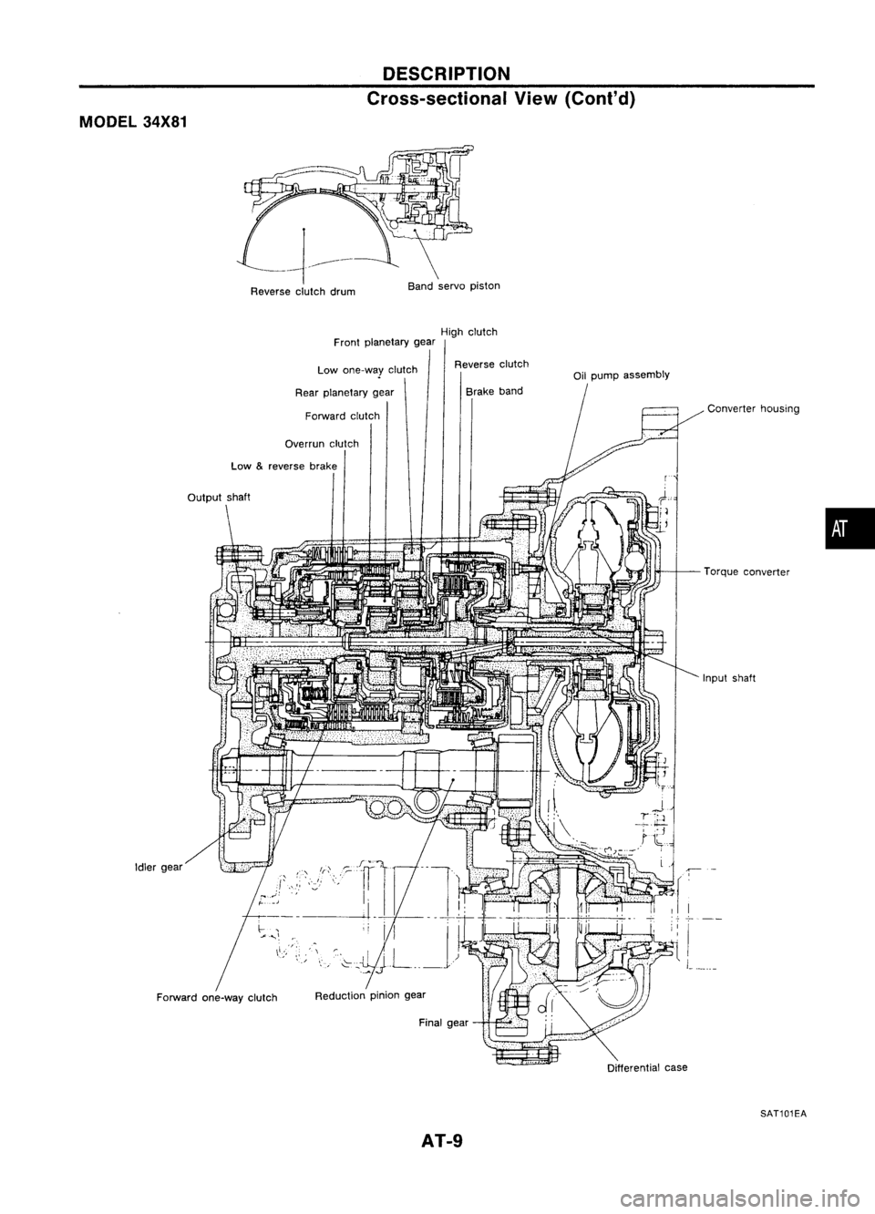
MODEL34X81 DESCRIPTION
Cross-sectional View(Cant' d)
Reverse clutchdrum Band
servo piston
High clutch
Front planetary gear
Reduction piniongear
Low
&
reverse brake
Idler gear
Forward one-way clutch Low
one-way clutch
Rear planetary gear
Forward clutch
Overrun clutch
,"'I
Reverse
clutch
Brake band
Final gear
AT-9
Oil
pump assembly
Converterhousing
Torque converter
Input shaft
c
...
-;-
I
L_
Differential case
SAT101EA
•
Page 11 of 1701

MODEL34X69AND34X70 DESCRIPTION
Hydraulic ControlCircuit(Cont'd)
00 cancel
solenoid
Lock-up
control
valve
X :
Drain port
•
1-2
shift valve
Forward
clutch
accumulator
valve
High
clutch
Torque
converter
Oil
pump
i
=:= :
Orifice
Overrun
clutch
II
control
valve
4th
speed
cut
valve
SAT509H
AT-11
Page 12 of 1701

DESCRIPTION
Hydraulic ControlCircuit(Cont'd)
MODEL 34X80
1-2
shift
valve
1-2
accumulator
valve
~ 1
i i
xU
::l.
x
-
Detent valve
L-
_
-
cooler- Low
&
reverse
Torque brake
Oil converter Overrun ReverseForward
I
,clutch Highclutch Bandservo clutchclutch
pump
I
tJ
(Jp::-
(T,
tf1
--;::;-;r.]O~
~J
1~
g~ (~ ~~
l]
J~ ~
~iJ -
N
~%~
UL"-'
IU4~1~~
C-1
-!
~frEJ!
1
6 ~, -~
m
~,--J
0
- ILJ
,-O...J
r
ar
r::r=< I'---,
II .(
I'
IJ
,'-
~
,,'
(
-
I -
=-
~tL ',
~H
I~
~ ~M~ ·
F=
f='l .,.11
1-
~I" ~
" ~r'
I
L...---...l
reducing_
L
2-3 .4-2
I
~valve= ~
shift ~seq!!.enc~
~ -valve ,-=-valve---j
h
1J;;;.Q"t....
=--=-.J
II
Ma~alve
lJl.
"~'L--.J
:;;; ~I 11
p
URNb'21
nn
=-.--'
I~
II
'i-V
D
I I -,
." c:
I
Throttle
':fj'~1 .
modifier
If.'
valve .
II
I
1"
";'Jnn!
l...,
:=~-' \~
Throttle valve ~Klckdown
modifier
valve
X
:Drain port
:::::: :Orifice
Pressure
regulator
valve
!lJF
D
00 cancel
I
~Y&
solenoid •
Pressure
modifier valve
Lock-up_
control
valve
4th
speed cut
valve
Overrun
clutch
control-
valve
-=~
I
r
rr=-
LL:
J~
L~
Torque
x'"~
converter
i
i
relief '
valve
2~ '-
3-4 shift valv~-HiliJI
Governor../l ..-
valve
SAT1971
AT-12
Page 13 of 1701

MODEL34X81
4th speed
cut valve
Lock-up
control valve
Overrun
clutch
control valve
3-4 shift valve
X Drainport
:::::= :
Orifice Oil
pump Torque
converter DESCRIPTION
Hydraulic ControlCircuit(Cont'd)
High clutch
AT-13 1-2
shift valve
SAT1981
•
Page 14 of 1701

DESCRIPTION
Shift Mechanism
CONSTRUCTION
18
,:-1
SAT214H
ill
Torque converter
@
Oilpump
@
Input shaft
@
Brake band
@
Reverse clutch
@
High clutch
o
Front sungear
@
Front pinion gear
@
Front internal gear
@l
Front planetary carrier
@
Rear sungear
@
Rear pinion gear
@
Rear internal gear
@
Rear planetary carrier
@
Forward clutch
@
Forward one-way clutch
@
Overrun clutch
@
Lowone-way clutch
@
Low
&
reverse brake
@
Parking pawl
@
Parking gear
@
Output shaft
@
Idlegear
@
Output gear
FUNCTION OFCLUTCH ANDBRAKE
Glutch andbrake components Abbr. Function
Reverse clutch
RIG
To
transmit inputpower tofront sungear
High clutch
HIG
To
transmit inputpower tofront planetary carrier
Forward clutch
FIG
To
connect frontplanetary carrierwithforward one-way clutch
Overrun clutch
OIG
To
connect frontplanetary carrierwithrearinternal gear
Brake band BIBTo
lock front sungear
Forward one-way clutch
F/O.G
When
forward clutchisengaged, tostop rearinternai gearfrom rotat-
ing inopposite direction againstenginespeed
Low one-way clutch LlO.GTo
stop front planetary carrierfromrotating inopposite direction
against enginespeed
Low
&
reverse brake L
&
RIB To
lock front planetary carrier
AT-14
Page 15 of 1701

DESCRIPTION
Shift Mechanism (Cont'd)
OPERATION OFCLUTCH ANDBRAKE
Bandservo
ForwardLow
Low
&
Shift posi- Reverse
HighForward
Overrun
Lock-upRemarks
tion clutch clutchclutchclutch 2nd
3rd4thone-way
one-way reverse
apply release
applyclutch
clutch brake
P PARK
POSITION
0 0REVERSE
POSI-
R TION
N NEUTRAL
POSI-
TION
1st 0'10
••
D 2nd
0'10
0
•
Automatic
shift
'4 00'10
'2@
@
•
1<-->2<-->3<-->4
3rd
4th 0@ '3@
@0
0
1st 00
••
Automatic
shift
2 1<-->2
2nd 00 0
•
1st 00
•
•
0
Locks
(heldsta-
1 tionary)
in1st
2nd 00 0
•
speed
1
<--
2
'1 Operates whenoverdrive switchissel to"OFF".
'2 Oilpressure isapplied toboth 2nd"apply" sideand3rd"release" sideofband servo piston. However, brakebanddoes notcontract
because oilpressure areaonthe "release" sideisgreater thanthatonthe "apply" side.
'3 Oilpressure isapplied to4th "apply" sideincondition '2above, andbrake bandcontracts.
'4 AIT
will notshift to4th when overdrive switchisset to"OFF" position.
o
Operates.
• Operates. During"progressive" acceleration.
@ Operates butdoes notaffect power transmission.
Control System
CONTROL SYSTEM
Engine
AIT
•
Lock-up cancel
solenoid'1
Overdrive
control switch
1:1
Governor valve
I
11
1
I
1
1
OD cancel solenoid :
; I
L
J
AT-15
'1:
Equipped onmodel
34X69, 34X70and34X80
: Electrical signal
.... :Hydraulic pressure
SAT985HA