ECO mode NISSAN ALMERA N15 1995 Service Manual
[x] Cancel search | Manufacturer: NISSAN, Model Year: 1995, Model line: ALMERA N15, Model: NISSAN ALMERA N15 1995Pages: 1701, PDF Size: 82.27 MB
Page 8 of 1701
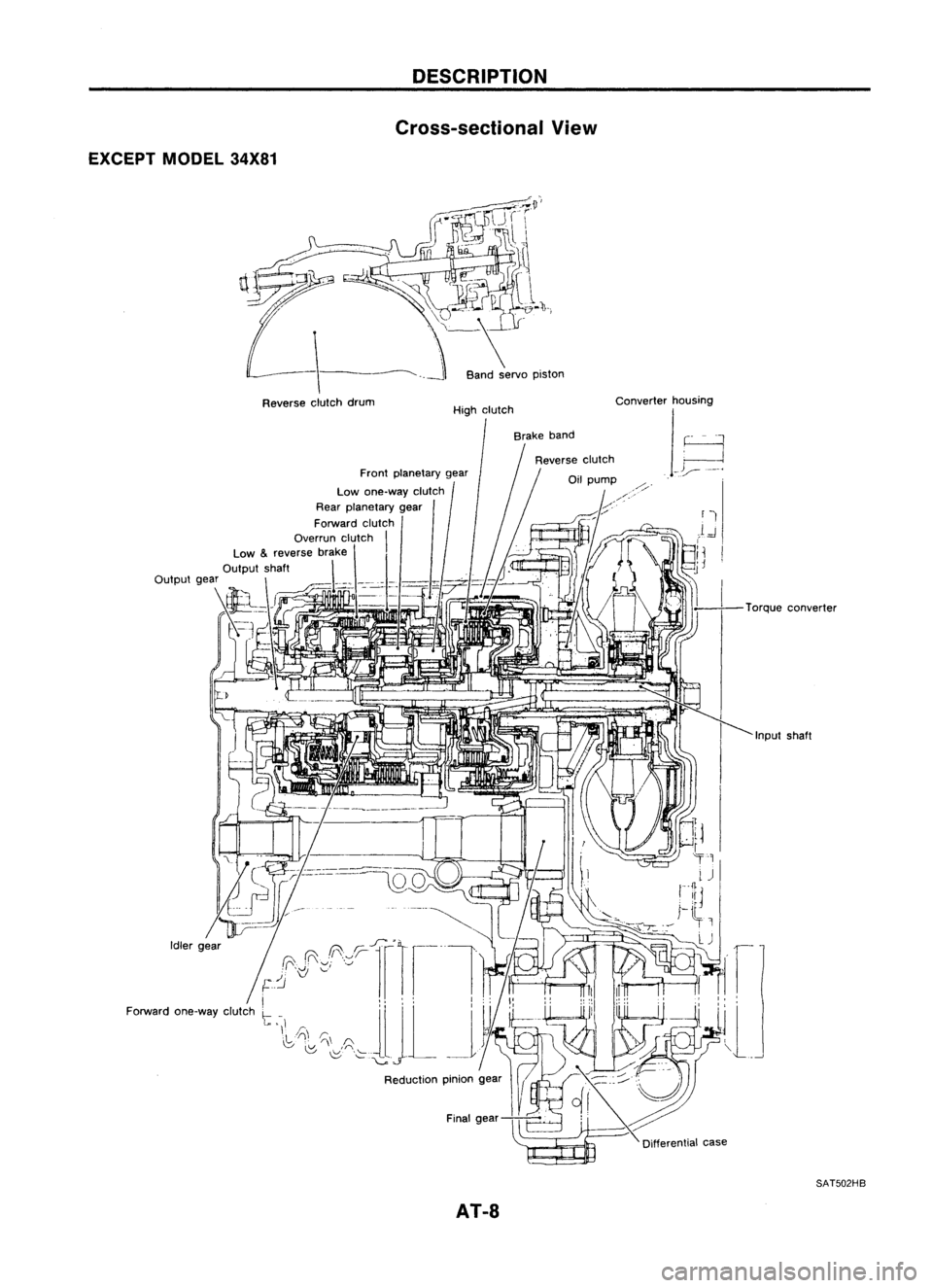
EXCEPTMODEL34X81
Reverse clutchdrum
DESCRIPTION
Cross-sectional View
Band servo piston
High clutch
Brake band
AT-8
Converter
housing
Torqueconverter
SAT502HB
Page 19 of 1701

TROUBLEDIAGNOSES
Road Testing (Cont'd)
SHIFT SCHEDULE
Drive thevehicle forapprox. 10minutes. Measuretheoiltem-
perature. Whentheoiltemperature becomesbetween50and
80°C (122and176°F), carryoutthis check.
VEHICLE SPEEDWHENSHIFTING GEARS
Model 34X68
Throttle posi- Vehicle
speedkm/h(MPH)
tion
0,~O
2
O
2
->
0
3
0
3
->
0
4
0
4
~
0
3
0
3
->
O
2
O
2
->
0,
1
2
~
1,
Full throttle
48
-56 88
-96 133
-141
80-88 37-45 45-53
(30 -35) (55-60)
-
(83-88)
(50-55) (23-28) (28
-33)
Half throttle
31
-39 54
-62 102-110
75-83 44
-52
7-15 45
-53
(19 -24) (34
-39)
(63-68) (47
-52)
(27-32) (4
-9)
(28-33)
Model 34X69and34X70
Throttle pas
i-
Vehicle
speedkm/h(MPH)
tion
0,~O
2
O
2~
0
3
0
3
->
0
4
0
4~
0
3
0
3
->
O
2
O
2~
0,
1
2~
1,
Full throttle
51
-60 94
-102 136-144
85-93 40
-48
48-56
(32 -37) (58-63)
-
(85-89)
(53-58) (25
-30) (30-35)
Half throttle
30
-38 52
-60 97-105 67-75 42-50 8-16
48-56
(19 -24) (32-37) (60-65) (42-47) (26-31) (5-10) (30-35)
Model 34X80
Throttle posi- Vehicle
speedkm/h(MPH)
tion
0,~O
2
O
2
->
0
3
0
3~
0
4
0
4
->
0
3
0
3
~
O
2
O
2
->
0,
1"
->
1,
Full throttle
52
-60 100-108 145
-153
90-98 40
-48 49-57
(32 -37) (62-67)
-
(90-95) (56-61) (25-30) (30
-35)
Half throttle
30
-38 53-61 103
-111
69-77 42
-50 8-16 49-57
(19 -24) (33-38) (64-69) (43-48) (26-31) (5-10) (30-35)
Model 34X81
Throttle posi- Vehicle
speedkm/h(MPH)
tion
0,~O
2
O
2
->
0
3
0
3
~
0
4
0
4
->
0
3
0
3
->
O
2
O
2
~
0,
1
2~
1,
Full throttle
58
-66 107
-115 160
-168
96-104 39
-47 48-56
(36 -41) (66
-71)
-
(99-104) (60-65) (24
-29) (30
-35)
33 -41 57-65 105
-113 69-77 45-53 8-16 48-56
Half throttle
(21-25) (35-40)
(65-70) (43
-48) (28-33) (5-10) (30
-35)
AT-19
•
Page 40 of 1701
REMOVALANDINSTALLATION
Installation
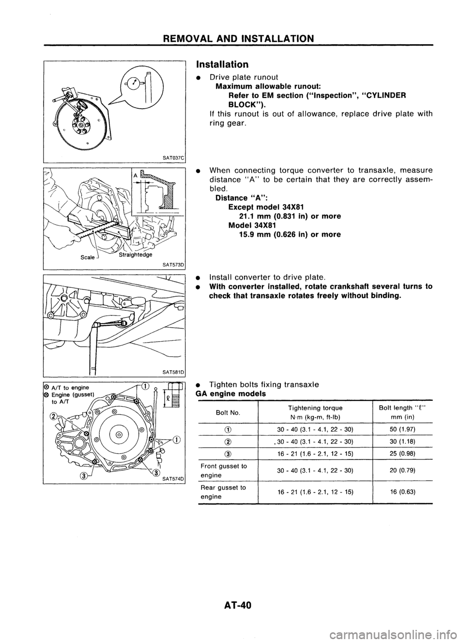
• Drive platerunout
Maximum allowablerunout:
Refer toEM section ("Inspection", "CYLINDER
BLOCK").
If this runout isout ofallowance, replacedriveplatewith
ring gear.
SAT037C
•When connecting torqueconverter totransaxle, measure
distance "A"tobe certain thatthey arecorrectly assem-
bled.
Distance
"A":
Except model34X81
21.1 mm(0.831 in)ormore
Model 34X81
15.9 mm(0.626 in)ormore
o
AIT
toengine
o
Engine (gusset)
to
AIT
SAT573D
•Install converter todrive plate.
• With converter installed,rotatecrankshaft severalturnsto
check thattransaxle rotatesfreelywithout binding.
• Tighten boltsfixing transaxle
GA engine models
Bolt No. Tightening
torque Boltlength
"e"
N.m (kg-m, ft-Ib) mm
(in)
G)
30-40 (3.1 -4.1,22 -30) 50
(1.97)
@ .30-40 (3.1 -4.1, 22-30) 30
(1.18)
@ 16
-21 (1.6 -2.1,12 -15) 25
(0.98)
Front gusset to
30-40 (3.1 -4.1,22 -30) 20
(0.79)
engine
Rear gusset to
16-21 (1.6 -2.1,12 -15) 16
(0.63)
engine
AT-40
Page 61 of 1701
Parkingshaft
SAT064D
SAT702D DISASSEMBL
V
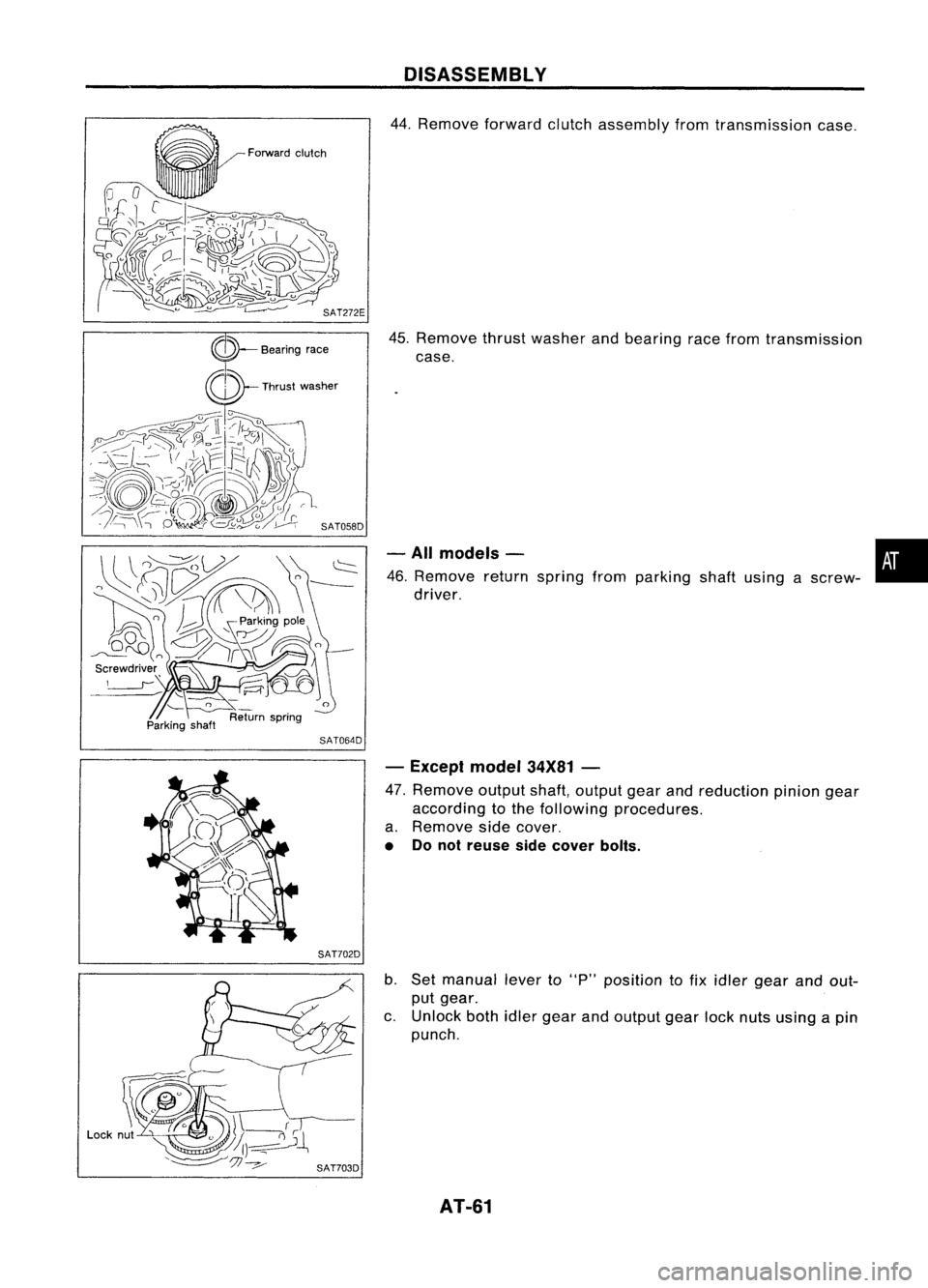
44. Remove forwardclutchassembly fromtransmission case.
45. Remove thrustwasher andbearing racefrom transmission
case.
- All models - •
46. Remove returnspring fromparking shaftusing ascrew-
i
driver.
- Except model34X81-
47. Remove outputshaft,output gearandreduction piniongear
according tothe following procedures.
a. Remove sidecover.
• Donot reuse sidecover bolts.
b. Set manual leverto"p" position tofix idler gear andout-
put gear.
c. Unlock bothidlergear andoutput gearlocknuts using apin
punch.
AT-61
Page 62 of 1701
SAT704D
Reduction
pinion gear
SAT706DADISASSEMBL
V
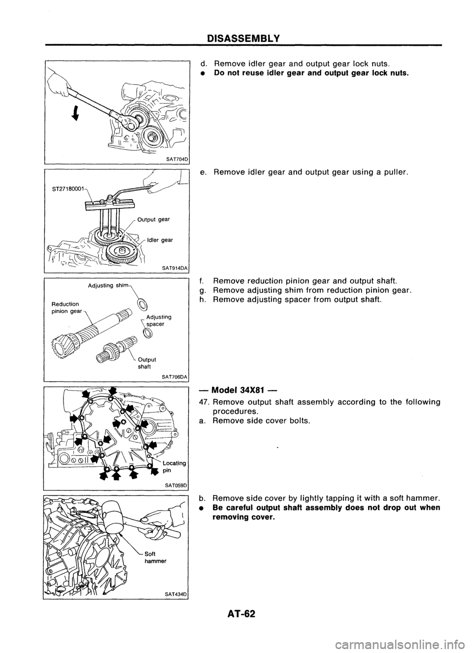
d. Remove idlergear andoutput gearlocknuts.
• Donot reuse idlergear andoutput gearlocknuts.
e. Remove idlergearandoutput gearusing apuller.
f. Remove reduction piniongearandoutput shaft.
g. Remove adjusting shimfromreduction piniongear.
h. Remove adjusting spacerfromoutput shaft.
- Model 34X81-
47. Remove outputshaftassembly according tothe following
procedures.
a. Remove sidecover bolts.
b. Remove sidecover bylightly tapping itwith asoft hammer.
• Becareful outputshaftassembly doesnotdrop outwhen
removing cover.
AT-62
Page 74 of 1701
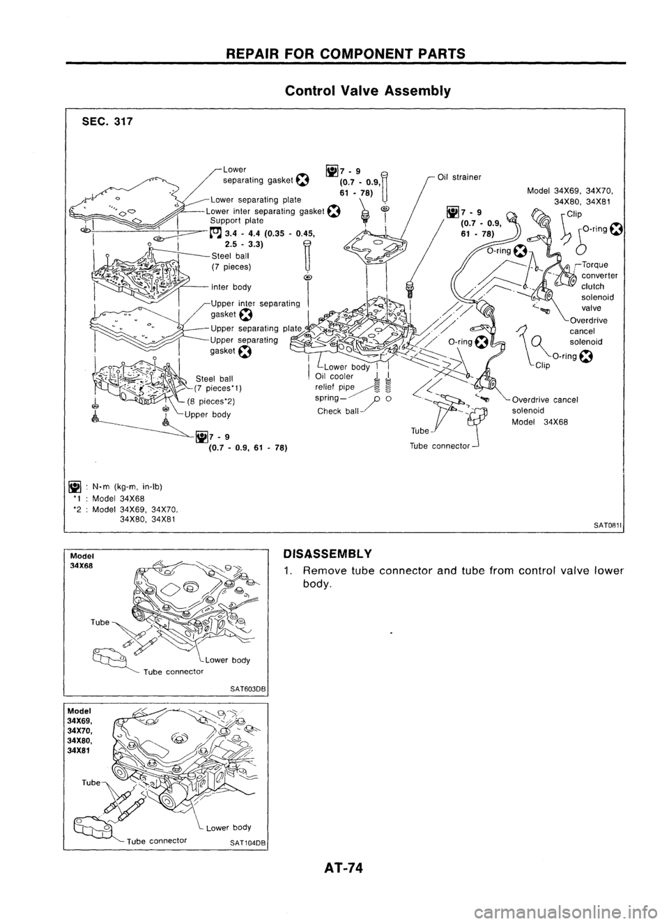
SEC.317
~ :N.m (kg-m, in-Ib)
'I :Model 34X68
'2 :Model 34X69, 34X70.
34X80, 34X81
Model
34X68
Model
34X69,
34X70.
34X80,
34X81 REPAIR
FORCOMPONENT PARTS
Control ValveAssembly
Model34X69, 34X70,
34X80, 34X81
\ Clip
~ 6-T1ng~
SATOB11
DISASSEMBL Y
1. Remove
tubeconnector andtube from control
valve
lower
body.
SAT603DB
SAT104DB AT-74
Page 75 of 1701

SAT245EB
Nut
Section Z- Z
Reamer bolt
•
Bolt
symbol
@
@ @@
CID
cD
Bolt length 'T'
13.558.0 40.0 66.033.078.0
~Qmm(in)
(0.531)
(2.283)(1.575)(2.598) (1.299)
(3.071)
Number ofbolts
4
3 611
22
Bolt symbol
@
@ @@
CID
CD
Bolt length" ("
13.558.0 40.0
66.0 33.078.0
~ (0.531)(2.283)
(1.575)(2.598) (1.299)(3.071)
>-,-1
Qmm (in)
Number ofbolts
53 611
22
With
torque converter clutchsolenoid valve
@
@
REPAIR
FORCOMPONENT PARTS
Control ValveAssembly (Cont'd)
2. Disassemble upper,interandlower bodies usingthefollow-
ing procedures.
Bolt length, number andlocation:
Without torqueconverter clutchsolenoid valve
CD
Plain
washer
Section
y- y
Model
34X68
Section Y- Y
@Bolt~
Support plate
f
(E)BOIt~
Support plate~
(f)
Plain
washer
Nut SAT515HB
Model 34X68
a.
Remove bolts@,@and
CB
shown inthe illustration.
b. Remove oilstrainer fromcontrol valveassembly.
AT-75
Page 76 of 1701
Model34X69. 34X70.34X80,34X81 REPAIR
FORCOMPONENT PARTS
Control ValveAssembly (Cont'd)
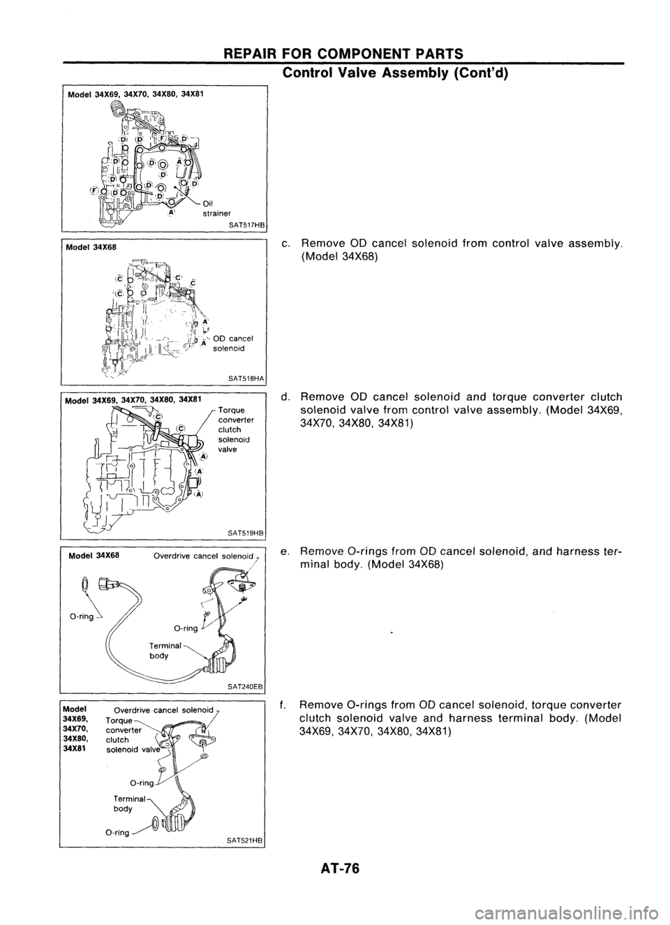
Model 34X68
c.
Remove aDcancel solenoid fromcontrol valveassembly.
(Model 34X68)
Model 34X69. 34X70,34X80.34X81
~)
Model 34X68
Ori~
Torque
converter
clutch
solenoid
valve
SAT519HB
SAT240EB
d.
Remove aDcancel solenoid andtorque converter clutch
solenoid valvefromcontrol valveassembly. (Model34X69,
34X70, 34X80, 34X81)
e. Remove a-ringsfromaDcancel solenoid, andharness ter-
minal body. (Model 34X68)
ModeJ
34X69.
34X70.
34X80.
34X81
Overdrive
cancelsolenoid
Torque
converter
clutch
'0
solenoid valv~
"
o_rin~
Terminal
0
body
O-ring~
l\
SAT521HB
f.
Remove a-ringsfromaDcancel solenoid, torqueconverter
clutch solenoid valveandharness terminal body.(Model
34X69, 34X70, 34X80,34X81)
AT-76
Page 82 of 1701
Lowerseparating
gasket REPAIR
FORCOMPONENT PARTS
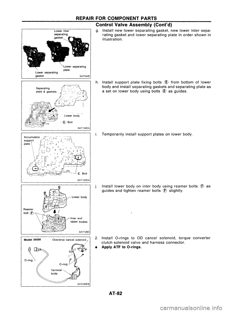
Control ValveAssembly (Cont'd)
g. Install newlower separating gasket,newlower intersepa-
rating gasket andlower separating plateinorder shown in
illustration.
Lower separating
plate
SAT244E
Separating
plate &gaskets
Lowerbody
> (~)
Boit
SAT124DA
h.
Install support platefixing bolts
CID
from bottom oflower
body andinstall separating gasketsandseparating plateas
a set onlower bodyusing bolts
CID
asguides.
SAT125DA
i.
Temporarily installsupport platesonlower body.
Model 34X68 Lower
body
Inter and
upper bodies
SAT126D
Overdrive cancelsolenoid 7
.'
j.
Install lowerbodyoninter body using reamer bolts
(f)
as
guides andtighten reamer bolts
(f)
slightly.
2. Install a-rings toaD cancel solenoid, torqueconverter
clutch solenoid valveandharness connector.
• Apply ATF
toO-rings.
AT-82
Page 83 of 1701
REPAIRFORCOMPONENT PARTS
Control ValveAssembly (Cont'd)
Model
34X69, 34X70,
34X80, 34X81 Overdrive
cancelsolenoid
Torque~ converter
clutch
'0
solenoid valv~
'"
o_rin~
Terminal
0
body
O-ring~
l\
SAT521HB
Section Z- Z
Reamer bolt
Model
34X68
•
Bolt
symbol
@
@
@
@
(!)
ffi
Bolt length "C"
13.558.0 40.0 66.0
33.078.0
~ Q
mm(in)
(0.531)
(2.283)(1.575) (2.598)(1.299)
(3.071)
Number ofbolts
4
3611
22
3.4 -
4.4 7-9
Tightening torque
7-9 (0.7 -0.9, 61-78) (0.35
-(0.7 -
N'm (kg-m, in-Ib)
0.45,
0.9,61
30.4 - -78)
39.1)
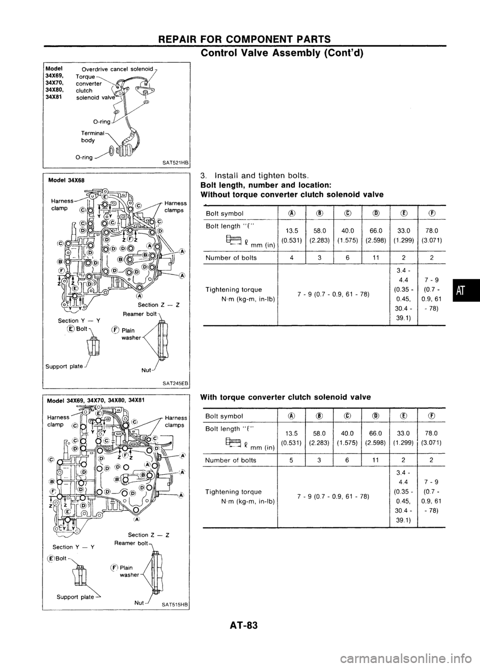
3.
Install andtighten bolts.
Bolt length, number andlocation:
Without torqueconverter clutchsolenoid valve
/
Nut
(:E)
Plain
washer
Section
y- y
@Bolt~
Support plate
r
SAT245EB
Section
y- y
Section
Z- Z
Reamer bolt With
torque converter clutchsolenoid valve
Bolt symbol
@
@
@
@
(!)
ffi
Bolt length "C"
13.558.0
40.0 66.033.0
78.0
~ Q
mm (in)
(0.531)
(2.283)
(1.575) (2.598)(1.299)
(3.071)
Number ofbolts
536
11 2
2
3.4 -
4.4 7-9
Tightening torque
7-9 (0.7 -0.9, 61-78) (0.35
-(0.7 -
N'm (kg-m, in-Ib)
0.45,
0.9,61
30.4 --
78)
39.1)
(ElBolt -
. S"PP~
en
Plain
washer
AT-83