run flat NISSAN ALMERA N15 1995 Service Manual
[x] Cancel search | Manufacturer: NISSAN, Model Year: 1995, Model line: ALMERA N15, Model: NISSAN ALMERA N15 1995Pages: 1701, PDF Size: 82.27 MB
Page 7 of 1701
\"AIR
BAG\" (DualAirBag System)
The Supplemental RestraintSystem\"AirBag\" usedalong withaseat belt, helps toredu")
PREPARATIONANDPRECAUTIONS
Service Notice
Supplemental RestraintSystem(SRS)"AIR
BAG" (DualAirBag System)
The Supplemental RestraintSystem"AirBag" usedalong withaseat belt, helps toreduce therisk or
severity ofinjury tothe driver andfront passenger inafrontal collision. TheSupplemental Restraint
System consists ofair bag modules (locatedinthe center ofthe steering wheelandonthe instrument
panel onthe passenger side),adiagnosis sensorunit,warning lamp,wiring harness andspiral cable.
Information necessarytoservice thesystem safelyisincluded inthe
RSsection
ofthis Service Manual.
WARNING:
• Toavoid rendering theSRS inoperative, whichcouldincrease therisk ofpersonal injuryordeath
in the event ofacollision whichwould resultinair bag inflation, allmaintenance mustbeperformed
by an authorized NISSANdealer.
• Improper maintenance, includingincorrectremovalandinstallation ofthe SRS, canlead topersonal
injury caused byunintentional activationofthe system.
Ii
Donot use electrical testequipment onany circuit related tothe SRS unless instructed tointhis
Service Manual. SRSwiring harnesses arecovered withyellow insulation eitherjustbefore the
harness connectors orfor the complete harness,foreasy identification.
•
Before proceeding withdisassembly, thor-
oughly cleantheoutside ofthe transaxle. Itis
important toprevent theinternal partsfrom
becoming contaminated bydirt orother for-
eign matter.
• Disassembly shouldbedone inaclean work
area.
• Use lint-free clothortowels forwiping parts
clean. Common shopragscanleave fibers
that could interfere withtheoperation ofthe
transaxle.
• Place disassembled partsinorder, onaparts
rack, foreasier andproper assembly.
• Allparts should becarefully cleaned-witha
general purpose, non-flammable solvent
before inspection orreassembly.
• Gaskets, sealsandO-rings shouldbe
replaced anytime thetransaxle isdisassem-
bled.
• Itis very important toperform functional tests
whenever theyareindicated. •
The valve bodycontains precision partsand
requires extremecarewhen partsare
removed andserviced. Placedisassembled
valve bodyparts inorder, onaparts rack,for
easier andproper assembly. Carewillalso
prevent springs andsmall partsfrombecom-
ing scattered orlost.
• Properly installedvales,sleeves, plugs,etc.
will slide along theirbores inthe valve body
under theirownweight.
• Before assembly, applyacoat ofrecom-
mended ATFtoall parts. Apply petroleum
jelly toprotect O-ringandseals, orhold bear-
ings andwashers inplace during assembly.
Do not use grease.
• Extremely careshould betaken toavoid dam-
age toO-rings, sealsandgaskets when
assembling.
• After overhaul, refillthetransaxle withnew
ATF.
•
Supplemental RestraintSystem(SRS)"AIR
BAG" (Single AirBag System)
The Supplemental RestraintSystem"AirBag" andused along withaseat belt,helps toreduce therisk
or severity ofinjury tothe driver inafrontal collision. TheSupplemental RestraintSystemconsists of
an air bag module (located inthe center ofthe steering wheel),adiagnosis sensorunit,warning lamp,
wiring harness andspiral cable. Information necessarytoservice thesystem safelyisincluded inthe
RS section
ofthis Service Manual.
WARNING:
• Toavoid rendering theSRS inoperative, whichcouldincrease therisk ofpersonal injuryordeath
in the event ofacollision whichwould resultinair bag inflation, allmaintenance mustbeperformed
by an authorized NISSANdealer.
• Improper maintenance, includingincorrectremovalandinstallation ofthe SRS, canlead topersonal
injury caused byunintentional activationofthe system.
• Donot use electrical testequipment onany circuit related tothe SRS unless instructed tointhis
Service Manual.
AT-7
Page 222 of 1701

PRECAUTIONS
Service Notice
• When removing orinstalling variousparts,placeacloth orpadding ontothevehicle bodytoprevent
scratches.
• Handle trim,molding, instruments, grille,etc.carefully duringremoving orinstalling. Becareful not
to soil ordamage them.
• Apply sealing compound wherenecessary wheninstalling parts.
• When applying sealingcompound, becareful thatthesealing compound doesnotprotrude from
parts.
• When replacing anymetal parts(forexample bodyouter panel, members, etc.),besure totake rust
prevention measures.
SupplementalRestraintSystem(SRS)"AIR
BAG" (DualAirBag System)
The Supplemental RestraintSystem"AirBag", usedalong withaseat belt,helps toreduce therisk or
severity ofinjury tothe driver andfront passenger inafrontal collision. TheSupplemental Restraint
System consists ofair bag modules (locatedinthe center ofthe steering wheelandonthe instrument
panel onthe passenger side),adiagnosis sensorunit,warning lamp,wiring harness andspiral cable.
Information necessarytoservice thesystem safelyisincluded inthe
RSsection
ofthis Service Manual.
WARNING:
• Toavoid rendering theSRS inoperative, whichcouldincrease therisk ofpersonal injuryordeath
in the event ofacollision whichwould resultinair bag inflation, allmaintenance mustbeperformed
by an authorized NISSANdealer.
• Improper maintenance, includingincorrectremovalandinstallation ofthe SRS, canlead topersonal
injury caused byunintentional activationofthe system.
• Donot use electrical testequipment onany circuit related tothe SRS unless instructed tointhis
Service Manual. SRSwiring harnesses arecovered withyellow insulation eitherjustbefore the
harness connectors orfor the complete harness,foreasy identification.
Supplemental RestraintSystem(SRS)"AIR
BAG" (Single AirBag System)
The Supplemental RestraintSystem"AirBag", usedalong withaseat belt,helps toreduce therisk or
severity ofinjury tothe driver inafrontal collision. TheSupplemental RestraintSystemconsists ofan
air bag module (located inthe center ofthe steering wheel),adiagnosis sensorunit,warning lamp,
wiring harness andspiral cable. Information necessarytoservice thesystem safelyisincluded inthe
RS section
ofthis Service Manual.
WARNING:
• Toavoid rendering theSRS inoperative, whichcouldincrease therisk ofpersonal injuryordeath
in the event ofacollision whichwould resultinair bag inflation, allmaintenance mustbeperformed
by an authorized NISSANdealer.
• Improper maintenance, includingincorrectremovalandinstallation ofthe SRS, canlead topersonal
injury caused byunintentional activationofthe system.
• Donot use electrical testequipment onany circuit related tothe SRS unless instructed tointhis
Service Manual.
BT-2
Page 273 of 1701
\"AIRBAG\"
(DUAL AIRBAG SYSTEM)
The Supplemental RestraintSystem\"AirBag\" usedalong with
a seat belt,helps toreduce")
PRECAUTIONSANDPREPARATION
Precautions
SUPPLEMENTAL RESTRAINTSYSTEM(SRS)"AIRBAG"
(DUAL AIRBAG SYSTEM)
The Supplemental RestraintSystem"AirBag" usedalong with
a seat belt,helps toreduce therisk orseverity ofinjury tothe
driver andfront passenger inafrontal collision. TheSupple-
mental Restraint Systemconsists ofair bag modules (located
in the center ofthe steering wheelandonthe instrument panel
on the passenger side),adiagnosis sensorunit,warning lamp,
wiring harness andspiral cable. Information necessarytoser-
vice thesystem safelyisincluded inthe
RSsection
ofthis Ser-
vice Manual.
WARNING:
• Toavoid rendering theSRS inoperatiYe, whichcouldincrease therisk ofpersonal injuryordeath
in the event ofacollision whichwould resultinair bag inflation, allmaintenance mustbeperformed
by an authorized NISSANdealer.
• Improper maintenance, includingincorrectremovalandinstallation ofthe SRS, canlead topersonal
injury caused byunintentional activationofthe system.
• Donot use electrical testequipment onany circuit related tothe SRS unless instructed tointhis
Service Manual. SRSwiring harnesses arecovered withyellow insulation eitherjustbefore the
harness connectors orfor the complete harness,foreasy identification.
SUPPLEMENTAL RESTRAINTSYSTEM(SRS)"AIRBAG"
(SINGLE AIRBAG SYSTEM)
The Supplemental RestraintSystem"AirBag" andused along withaseat belt,helps toreduce therisk
or severity ofinjury tothe driver inafrontal collision. TheSupplemental RestraintSystemconsists of
an air bag module (located inthe center ofthe steering wheel),adiagnosis sensorunit,warning lamp,
wiring harness andspiral cable. Information necessarytoservice thesystem safelyisincluded inthe
RS section
ofthis Service Manual.
WARNING:
• Toavoid rendering theSRS inoperative, whichcouldincrease therisk ofpersonal injuryordeath
in the event ofacollision whichwould resultinair bag inflation, allmaintenance mustbeperformed
by an authorized NISSANdealer.
• Improper maintenance, includingincorrectremovalandinstallation ofthe SRS, canlead topersonal
injury caused byunintentional activationofthe system.
• Donot use electrical testequipment onany circuit related tothe SRS unless instructed tointhis
Service Manual.
BR-3
•
Page 376 of 1701
\"AIR
BAG\" (DualAirBag System)
The Supplemental RestraintSystem\"AirBag\", usedalong withaseat belt,helps toreduce therisk or
severity ofinju")
PRECAUTIONS
Supplemental RestraintSystem(SRS)"AIR
BAG" (DualAirBag System)
The Supplemental RestraintSystem"AirBag", usedalong withaseat belt,helps toreduce therisk or
severity ofinjury tothe driver andfront passenger inafrontal collision. TheSupplemental Restraint
System consists ofair bag modules (locatedinthe center ofthe steering wheelandonthe instrument
panel onthe passenger side),adiagnosis sensorunit,warning lamp,wiring harness andspiral cable.
Information necessarytoservice thesystem safelyisincluded inthe
RSsection
ofthis Service Manual.
WARNING:
• Toavoid rendering theSRS inoperative, whichcouldincrease therisk ofpersonal injuryordeath
in the event ofacollision whichwould resultinair bag inflation, allmaintenance mustbeperformed
by an authorized NISSANdealer.
• Improper maintenance, includingincorrectremovalandinstallation ofthe SRS, canlead topersonal
injury caused byunintentional activationofthe system.
• Donot use electrical testequipment onany circuit related tothe SRS unless instructed tointhis
Service Manual. SRSwiring harnesses arecovered withyellow insulation eitherjustbefore the
harness connectors orfor the complete harness,foreasy identification.
Supplemental RestraintSystem(SRS)"AIR
BAG" (Single AirBag System)
The Supplemental RestraintSystem"AirBag", usedalong withaseat belt,helps toreduce therisk or
severity ofinjury tothe driver inafrontal collision. TheSupplemental RestraintSystemconsists ofan
air bag module (located inthe center ofthe steering wheel),adiagnosis sensorunit,warning lampand
spiral cable. Information necessarytoservice thesystem safelyisincluded inthe
RSsection
ofthis
Service Manual.
WARNING: • Toavoid rendering theSRS inoperative, whichcouldincrease therisk ofpersonal injuryordeath
in the event ofacollision whichwould resultinair bag inflation, allmaintenance mustbeperformed
by an authorized NISSANdealer.
• Improper maintenance, includingincorrectremovalandinstallation ofthe SRS, canlead topersonal
injury caused byunintentional activationofthe system.
• Donot use electrical testequipment onany circuit related tothe SRS.
EL-4
Page 688 of 1701
.
*: Fuel, radiator coolantandengine oilfull. Spare tire,jack,
hand too")
ON-VEHICLESERVICE
Front Wheel Alignment
Before checking frontwheel alignment, besure tomake apre-
liminary inspection (Unladen*).
*: Fuel, radiator coolantandengine oilfull. Spare tire,jack,
hand tools andmats indesignated positions.
SFA575B PRELIMINARY INSPECTION
1. Check tiresforwear andimproper inflation.
2. Check wheelrunout.
Wheel runout:
Refer toSOS (FA-30).
3. Check frontwheel bearings forlooseness.
4. Check frontsuspension forlooseness.
5. Check steering linkageforlooseness.
6. Check thatstruts workproperly.
7. Check vehicle posture (Unladen).
TOE-IN Measure toe-inusingfollowing procedure.
WARNING:
• Perform following procedure alwaysonaflat surface.
• Make surethatnoperson isin front ofthe vehicle before
pushing it.
1. Bounce frontofvehicle upand down tostabilize theposture.
2. Push thevehicle straight aheadabout5m (16 ft).
3. Put amark onbase lineoftread (rearside) ofboth tires at
the same height ashub center. Thesearemeasuring points.
4. Measure distance"A"(rear side).
5. Push thevehicle slowlyaheadtorotate thewheels 180
degrees (1/2turn).
If the wheels haverotated morethan180degrees
(112
turn), try
the above procedure againfromthebeginning. Neverpush
vehicle backward.
6. Measure distance"B"(front side).
Total toe-in
Refer toSOS (FA-29).
CAMBER,
CASTERANDKINGPIN INCLINATION
Camber, casterandkingpin inclination arepreset atfactory and
cannot beadjusted.
1. Measure camber,casterandkingpin inclination ofboth right
and leftwheels withasuitable alignment gauge.
Camber, CasterandKingpin inclination:
Refer toSOS (FA-29).
2. Ifcamber, casterorkingpin inclination isnot within
specification, inspectfrontsuspension parts.Replace dam-
aged orworn outparts.
Front
SFA948A
SFA614B
SFA234AC
Lines
parallel to
center lineofbody
Q
Front
Hub
center
height
FA-6
Page 726 of 1701
\"AIR
BAG\" (DualAirBag System)
The Supplemental RestraintSystem\"AirBag\", usedalong withaseat belt,helps toreduce therisk or
s")
PRECAUTIONSANDPREPARATION
Supplemental RestraintSystem(SRS)"AIR
BAG" (DualAirBag System)
The Supplemental RestraintSystem"AirBag", usedalong withaseat belt,helps toreduce therisk or
severity ofinjury tothe driver andfront passenger inafrontal collision. TheSupplemental Restraint
System consists ofair bag modules (locatedinthe center ofthe steering wheelandonthe instrument
panel onthe passenger side),adiagnosis sensorunit,warning lamp,wiring harness andspiral cable.
Information necessarytoservice thesystem safelyisincluded inthe
RSsection
ofthis Service Manual.
WARNING:
• Toavoid rendering theSRS inoperative, whichcouldincrease therisk ofpersonal injuryordeath
in the event ofacollision whichwould resultinair bag inflation, allmaintenance mustbeperformed
by an authorized NISSANdealer. •
• Improper maintenance, includingincorrectremovalandinstallation ofthe SRS, canlead topersonal
injury caused byunintentional activationofthe system.
• Donot use electrical testequipment ~nany circuit related tothe SRS unless instructed tointhis
Service Manual. SRSwiring harnesses arecovered withyellow insulation eitherjustbefore the
harness connectors orfor the complete harness,foreasy identification.
Supplemental RestraintSystem(SRS)"AIR
BAG" (Single AirBag System)
The Supplemental RestraintSystem"AirBag", usedalong withaseat belt, helps toreduce therisk or
severity ofinjury tothe driver inafrontal collision. TheSupplemental RestraintSystemconsists ofan
air bag module (located inthe center ofthe steering wheel),adiagnosis sensorunit,warning lamp,
wiring harness andspiral cable. Information necessarytoservice thesystem safelyisincluded inthe
RS section
ofthis Service Manual.
WARNING: • Toavoid rendering theSRS inoperative, whichcouldincrease therisk ofpersonal injuryordeath
in the event ofacollision whichwould resultinair bag inflation, allmaintenance mustbeperformed
by an authorized NISSANdealer.
• Improper maintenance, includingincorrectremovalandinstallation ofthe SRS, canlead topersonal
injury caused byunintentional activationofthe system.
• Donot use electrical testequipment onany circuit related tothe SRS unless instructed tointhis
Service Manual.
EC-7
Page 1267 of 1701

12. Remove valveoilseal with asuitable tool.
Inspection
CYLINDER HEADDISTORTION
. Head surface flatness:
Standard Less than0.03mm(0.0012 in)
Limit
0.1 m")
SEM925CCYLINDER
HEAD
Disassembly (Cont'd)
12. Remove valveoilseal with asuitable tool.
Inspection
CYLINDER HEADDISTORTION
. Head surface flatness:
Standard Less than0.03mm(0.0012 in)
Limit
0.1 mm (0.004 in)
If beyond thespecified limit,replace orresurface.
Resurfacing limit:
The resurfacing limitofcylinder headisdetermined bythe cyl-
inder block resurfacing inan engine.
Amount ofcylinder headresurfacing is
"A".
Amount ofcylinder blockresurfacing is
"B".
The maximum limitisas follows:
A
+
B
=
0.2 mm (0.008 in)
After resurfacing cylinderhead,check thatcamshaft rotates
freely byhand. Ifresistance isfelt, cylinder headmustbe
replaced.
Nominal cylinderheadheight:
136.9 -137.1 mm(5.390 -5.398 in)
CAMSHAFT VISUALCHECK
Check camshaft forscratches, seizureandwear.
CAMSHAFT RUNOUT
1. Measure camshaft runoutatthe center journal.
Runout (Totalindicator reading):
Standard Less than0.02mm(0.0008 in)
Limit
0.1 mm (0.004 in)
2. Ifitexceeds thelimit, replace camshaft.
EM-88
Page 1339 of 1701

Inspection andAdjustment (Cont'd)
CAMSHAFT ANDCAMSHAFT BEARING CYLINDERBLOCK
Camshaft
Unit:
mm(in)
Unit: mm(in)
GA16DE GA16DE
GA16DE with
with
Engine GA14DEGA1")
SERVICEOATAAND SPECIFICATIONS (SOS)
Inspection andAdjustment (Cont'd)
CAMSHAFT ANDCAMSHAFT BEARING CYLINDERBLOCK
Camshaft
Unit:
mm(in)
Unit: mm(in)
GA16DE GA16DE
GA16DE with
with
Engine GA14DEGA15DE without
VTC
VTC
for
model
VTC
except
Aus-
for tralia
Europe
39,880 -
39,380 -40,610
-
40,610 -
Q)
40070
39,570
40,800
40800
""
(1.5701
-(1.5504 -(1.5988 -(1.5988 -
<1l
39,380 -
Cam
C
1.5776)1.5579)1.6063) 1.6063)
39.570
height
-
"A" (1,5504
-
40.056 -39.880 -
40.056 -39.91
-
U;
1.5579)
40.24640,07040.246 40.100
:::l
<1l
(1.5770-(1.5701-(1.5770 -(1.5713 -
.c
x
1,5845)1,5776)
1.5845) 1,5787)
w
Cam wear
0.20(0.0079)
limit
EM671
Camshaft bearing
Unit:mm(in)
Standard Limit
Camshaft journaltobear- 0,045
-0.086
0,15(0.0059)
ing clearance (00018-0.0034)
NO.1 28.000
-28,021
Inner diameter
(1.1024-1 1032)
of camshaft
-
bearing No.
2to 24,000
-24021
No, 5 (0.9449
-0.9457)
NO.1 27.935
-27.955
Outer diameter
(1,0998-1.1006)
of camshaft
.-
journal No.
2to 23935
-23.955
No, 5 (0,9423
-0,9431)
Camshaft runout[TIR'1] Less
than
01(0,004)
0.02 (0.0008)
0070 -0 143
(0,0028 -
Camshaft endplay 0.0056)'2
020(0,0079)
0,115 -0,188
(0.0045 -
0.0074)'3
T
1
Crankshaftcenter
SEM171D
GA14DE GA16DE
GA15DE Limit
Standard
Surface flatness Less
than
0,1(0,004)
0,03 (0.0012)
Height "H"(nominal) 213.95
-214.05
-
(8.4232 -8.4271)
Standard Inner diameter
73.600- 76.000-
Grade No.1 73,610
76,010
(2.8976 -(2,9921
-
2.8980) 2.9925)
73.610 - 76.010
-
Grade NO.2 73,620
76020
0.2(0,008)
(2.8980 -(2.9925
-
2.8984) 2.9929)
73,620 - 76.020-
Grade No.3 73.630
76.030
(2,8984 -(2.9929 -
2.8988) 2,9933)
Out-ot-round Less
than
-
(X -Yi
0,015
(0.0006)
Less than
Taper (A-B)
._-
0.01 (0.0004)
Difference ininner
diameter between 005
(0,0020) 0,2
(0.008)
cylinders
'1: Total indicator reading
'2: GA 16DE without
VTC
and 14DE
'3: GA16DE withVTC andGA15DE
EM-160
Page 1350 of 1701

COMPRESSION PRESSURE Inspection
andAdjustment
VALVE
Standard
Limit
Difference limit
between cylinders
CYLINDER HEAD
Head surface flatness
Standard Limit
Nominal")
SERVICEDATAANDSPECIFICATIONS (SDS)
COMPRESSION PRESSURE Inspection
andAdjustment
VALVE
Standard
Limit
Difference limit
between cylinders
CYLINDER HEAD
Head surface flatness
Standard Limit
Nominal cylinderhead
height Unit:
kPa(bar, kg/cm
2,
psi)at
200
rpm
3,138 (31.4, 32,455)
2,452 (24.5, 25,356)
490 (4.9, 5,71)
Unit: mm(in)
Less than
0.05(0.0020)
0.1 (0,004)
137.9 -138.1
(5.429 -5.437)
T
(Margin thickness)
1t
f"~ if
Valve headdiameter "D"
Intake
Exhaust
Valve length "L" Unit:
mm(in)
SEM188
39.0 -39.3 (1.535 -1.547)
32.0 -32.2 (1,260 -1.268)
•
CAMSHAFT ANDCAMSHAFT BEARING
Camshaft journal
clearance
Inner diameter of
camshaft bearing
Outer diameter of
camshaft journal
Camshaft runout
Camshaft endplay Standard
0.045 -0.086
(0.0018 -0.0034)
30.000 -30.021
(1.1811 -1.1819)
29.935 -29.955
(1.1785 -11793)
Less than
0.02 (0.0008)
0.115 -0.188
(0.0045 -0.0074)
Unit:
mm(in)
Max. tolerance
0.1 (0.004)
0.05 (0.0020)
EM671
Intake
Exhaust
Valve stemdiameter "d"
Intake
Exhaust
Valve seatangle "u"
Valve margin
"r
limit
Valve stemendsurface grinding
limit
100.53
-100.97
(3.9579 -3.9752)
100.38 -100.82
(3.9520 -3.9693)
6.965 -6.980
(0.2742 -0.2748)
6.945 -6.960
(0.2734 -0.2740)
45°30'
0.5 (0.020)
0.5 (0.020)
Cam height "A"
Intake
Exhaust
49.20
-49.25 (1.9370 -1.9390)
49.15 -49.20 (1.9350 -1.9370)
EM-171
Page 1356 of 1701
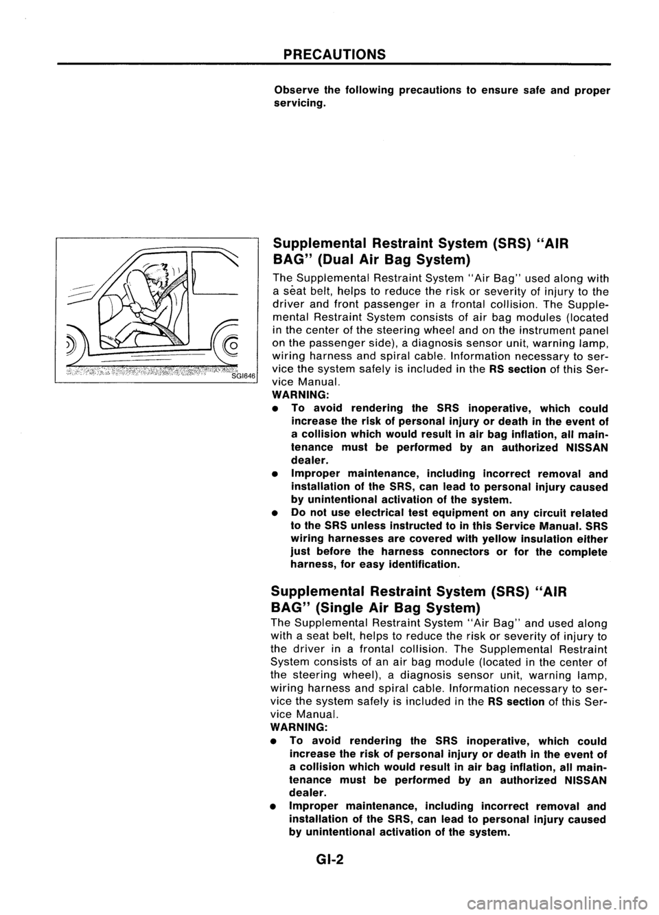
PRECAUTIONS
Observe thefollowing precautions toensure safeandproper
servicing.
Supplemental RestraintSystem(SRS)"AIR
BAG" (DualAirBag System)
The Supplemental RestraintSystem"AirBag" usedalong with
a seat belt,helps toreduce therisk orseverity ofinjury tothe
driver andfront passenger inafrontal collision. TheSupple-
mental Restraint Systemconsists ofair bag modules (located
in the center ofthe steering wheelandonthe instrument panel
on the passenger side),adiagnosis sensorunit,warning lamp,
wiring harness andspiral cable. Information necessarytoser-
vice thesystem safelyisincluded inthe RSsection ofthis Ser-
vice Manual.
WARNING:
• To avoid rendering theSRS inoperative, whichcould
increase therisk ofpersonal injuryordeath inthe event of
a collision whichwould resultinair bag inflation, allmain-
tenance mustbeperformed byan authorized NISSAN
dealer.
• Improper maintenance, includingincorrectremovaland
installation ofthe SRS, canlead topersonal injurycaused
by unintentional activationofthe system.
• Donot use electrical testequipment onany circuit related
to the SRS unless instructed tointhis Service Manual. SRS
wiring harnesses arecovered withyellow insulation either
just before theharness connectors orfor the complete
harness, foreasy identification.
Supplemental RestraintSystem(SRS)"AIR
BAG" (Single AirBag System)
The Supplemental RestraintSystem"AirBag" andused along
with aseat belt, helps toreduce therisk orseverity ofinjury to
the driver inafrontal collision. TheSupplemental Restraint
System consists ofan air bag module (located inthe center of
the steering wheel),adiagnosis sensorunit,warning lamp,
wiring harness andspiral cable. Information necessarytoser-
vice thesystem safelyisincluded inthe RSsection ofthis Ser-
vice Manual.
WARNING:
• To avoid rendering theSRS inoperative, whichcould
increase therisk ofpersonal injuryordeath inthe event of
a collision whichwould resultinair bag inflation, allmain-
tenance mustbeperformed byan authorized NISSAN
dealer.
• Improper maintenance, includingincorrectremovaland
installation ofthe SRS, canlead topersonal injurycaused
by unintentional activationofthe system.
GI-2