spark plugs replace NISSAN ALMERA N15 1995 Service Manual
[x] Cancel search | Manufacturer: NISSAN, Model Year: 1995, Model line: ALMERA N15, Model: NISSAN ALMERA N15 1995Pages: 1701, PDF Size: 82.27 MB
Page 777 of 1701
TROUBLEDIAGNOSIS -General Description
Sensors
~ ECMActuators
~~.~ MEF036D
SEF234G Introduction
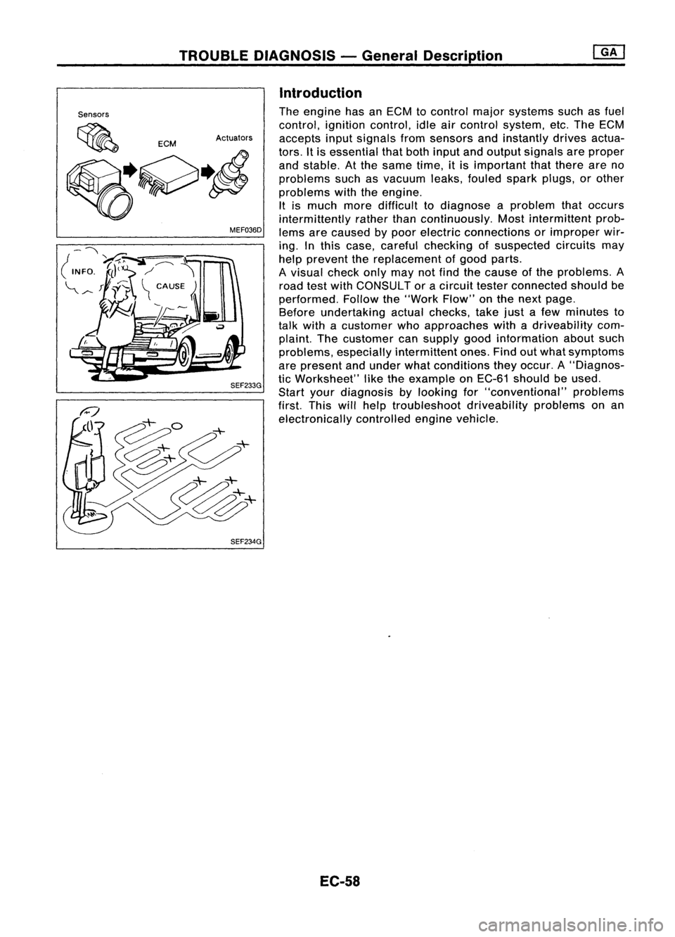
The engine hasanECM tocontrol majorsystems suchasfuel
control, ignitioncontrol, idleaircontrol system, etc.The ECM
accepts inputsignals fromsensors andinstantly drivesactua-
tors. Itis essential thatboth input andoutput signals areproper
and stable. Atthe same time,itis important thatthere areno
problems suchasvacuum leaks,fouled sparkplugs, orother
problems withtheengine.
It is much moredifficult todiagnose aproblem thatoccurs
intermittently ratherthancontinuously. Mostintermittent prob-
lems arecaused bypoor electric connections orimproper wir-
ing. Inthis case, careful checking ofsuspected circuitsmay
help prevent thereplacement ofgood parts.
A visual checkonlymaynotfind thecause ofthe problems. A
road testwith CONSULT oracircuit testerconnected shouldbe
performed. Followthe"Work Flow"onthe next page.
Before undertaking actualchecks, takejustafew minutes to
talk with acustomer whoapproaches withadriveability com-
plaint. Thecustomer cansupply goodinformation aboutsuch
problems, especially intermittent ones.Findoutwhat symptoms
are present andunder whatconditions theyoccur. A"Diagnos-
tic Worksheet" liketheexample onEC-61 should beused.
Start yourdiagnosis bylooking for"conventional" problems
first. Thiswillhelp troubleshoot driveabilityproblemsonan
electronically controlledenginevehicle.
EC-58
Page 983 of 1701
TROUBLEDIAGNOSIS -General Description
Sensors
~ ECMActuators
~~.~ MEF036D
SEF234G Introduction
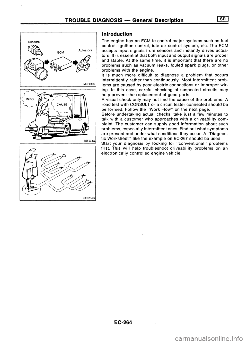
The engine hasanECM tocontrol majorsystems suchasfuel
control, ignitioncontrol, idleaircontrol system, etc.The ECM
accepts inputsignals fromsensors andinstantly drivesactua-
tors. Itis essential thatboth input andoutput signals areproper
and stable. Atthe same time,itis important thatthere areno
problems suchasvacuum leaks,fouled sparkplugs, orother
problems withtheengine.
It is much moredifficult todiagnose aproblem thatoccurs
intermittently ratherthancontinuously. Mostintermittent prob-
lems arecaused bypoor electric connections orimproper wir-
ing. Inthis case, careful checking ofsuspected circuitsmay
help prevent thereplacement ofgood parts.
A visual checkonlymaynotfind thecause ofthe problems. A
road testwith CONSULT oracircuit testerconnected shouldbe
performed. Followthe"Work Flow"onthe next page.
Before undertaking actualchecks, takejustafew minutes to
talk with acustomer whoapproaches withadriveability com-
plaint. Thecustomer cansupply goodinformation aboutsuch
problems, especially intermittent ones.Findoutwhat symptoms
are present andunder whatconditions theyoccur. A"Diagnos-
tic Worksheet" liketheexample onEC-267 shouldbeused.
Start yourdiagnosis bylooking for"conventional" problems
first. Thiswillhelp troubleshoot driveabilityproblemsonan
electronically controlledenginevehicle.
EC-264
Page 1194 of 1701
COMPRESSIONPRESSURE
20
mm
(O.79 In)dls.
Use compressor testerwhose end(rubber
portion) isless than 20mm (0.79 in)dia.
Otherwise, itmay becaught bycylinder
head during removal.
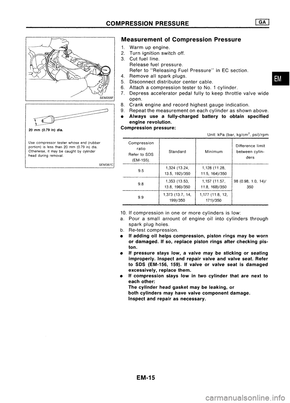
SEM387CMeasurement
ofCompression Pressure
1. Warm upengine.
2. Turn ignition switchoff.
3. Cut fuel line.
Release fuelpressure.
Refer to"Releasing FuelPressure" inEC section. •
4. Remove allspark plugs.
5. Disconnect distributorcentercable.
6. Attach acompression testertoNO.1 cylinder.
7. Depress accelerator pedalfullytokeep throttle valvewide
open.
8. Crank engine andrecord highest gaugeindication.
9. Repeat themeasurement oneach cylinder asshown above.
• Always useafully-charged batterytoobtain specified
engine revolution.
Compression pressure:
Unit:kPa(bar, kg/cm
2,
psi)/rpm
Compression Differencelimit
ratio
Standard
Refer toSOS Minimum
betweencylin-
(EM-155). ders
9.5 1,324
(13.24, 1,128(11.28,
13.5, 192)/350 11.5,164)/350
9.8 1,353
(1353, 1,157(11.57, 98(0.98, 1.0,14)/
13.8, 196)/350 11.8,168)/350
350
9.9 1,373
(13.7, 14, 1,177(11.8,12,
199)/350 171)/350
10.
If
compression inone ormore cylinders islow:
a. Pour asmall amount ofengine oilinto cylinders through
spark plugholes.
b. Re-test compression,
• Ifadding oilhelps compression, pistonringsmaybeworn
or damaged. Ifso, replace pistonringsafterchecking pis-
ton.
• Ifpressure stayslow,avalve maybesticking orseating
improperly. Inspectandrepair valveandvalve seat.Refer
to SOS (EM-156, 159).Ifvalve orvalve seatisdamaged
excessively, replacethem.
• Ifcompression stayslowintwo cylinder thatarenext to
each other:
The cylinder headgasket maybeleaking, or
both cylinders mayhave valve component damage.
Inspect andrepair asnecessary.
EM-15
Page 1220 of 1701
VALVECLEARANCE
1 1 22
2 2 44
SEM140D Checking
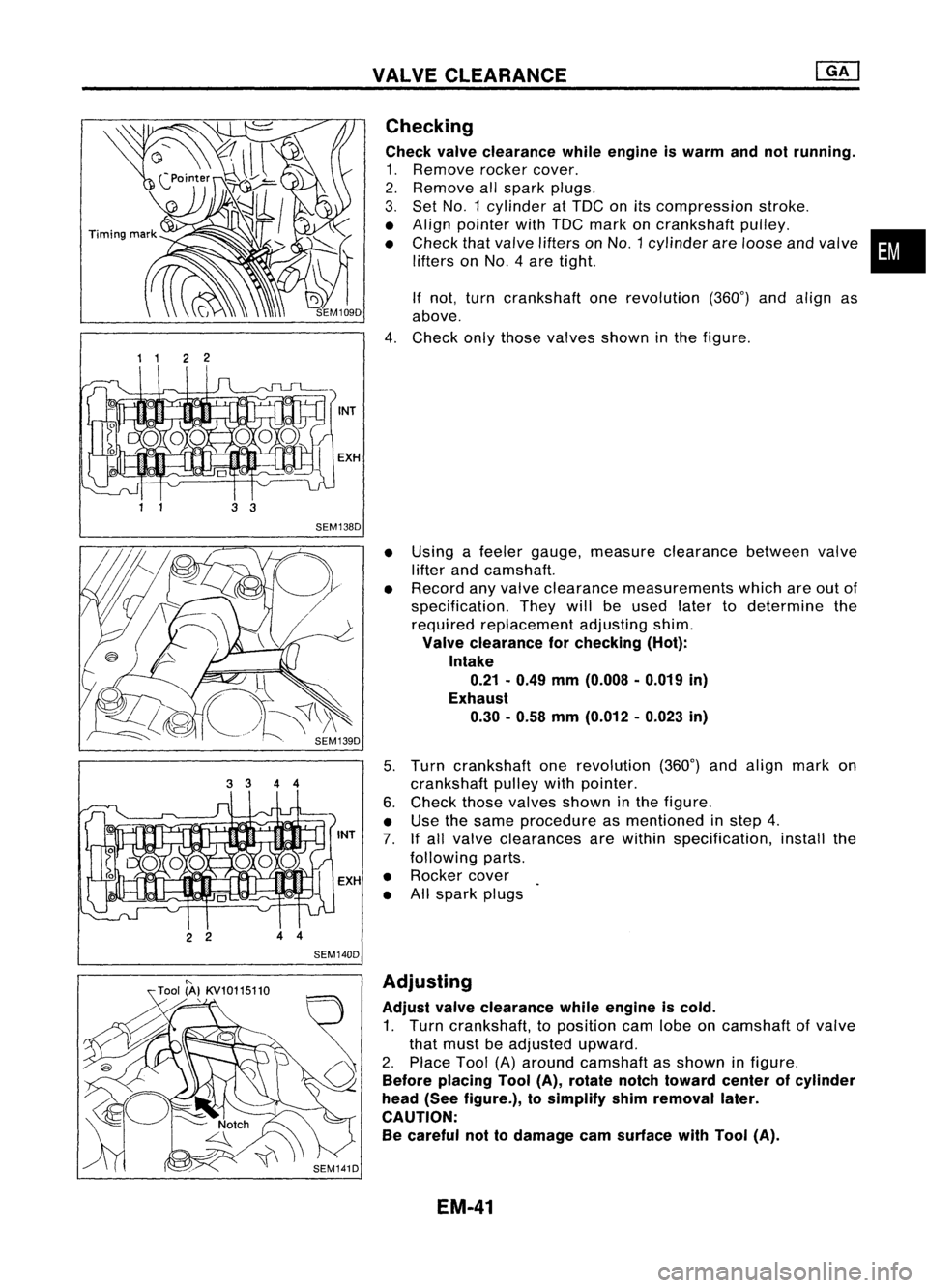
Check valveclearance whileengine iswarm andnotrunning.
1. Remove rockercover.
2. Remove allspark plugs.
3. Set
NO.1
cylinder atTOC onitscompression stroke.
• Align pointer withTOC mark oncrankshaft pulley.
• Check thatvalve lifters on
NO.1
cylinder areloose andvalve
lifters on
NO.4
aretight.
If not, turn crankshaft onerevolution (360°)andalign as
above.
4. Check onlythose valves showninthe figure.
• Using afeeler gauge, measure clearance betweenvalve
lifter andcamshaft.
• Record anyvalve clearance measurements whichareoutof
specification. Theywillbeused latertodetermine the
required replacement adjustingshim.
Valve clearance forchecking (Hot):
Intake 0.21 -0.49 mm(0.008 .0.019 in)
Exhaust 0.30. 0.58mm(0.012 -0.023 in)
5. Turn crankshaft onerevolution (360°)andalign markon
crankshaft pulleywithpointer.
6. Check thosevalves shown inthe figure.
• Use thesame procedure asmentioned instep 4.
7. Ifall valve clearances arewithin specification, installthe
following parts.
• Rocker cover
• Allspark plugs
•
"-
Tool (A}KV10115110
,
SEM141DAdjusting
Adjust valveclearance whileengine iscold.
1. Turn crankshaft, toposition camlobeoncamshaft ofvalve
that must beadjusted upward.
2. Place Tool(A)around camshaft asshown infigure.
Before placing Tool(A),rotate notchtoward centerofcylinder
head (Seefigure.), tosimplify shimremoval later.
CAUTION: Be careful nottodamage camsurface withTool (A).
EM-41
Page 1241 of 1701
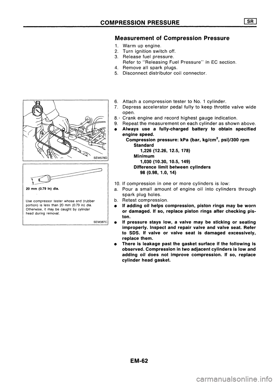
COMPRESSIONPRESSURE
Measurement ofCompression Pressure
1. Warm upengine.
2. Turn ignition switchoff.
3. Release fuelpressure.
Refer to"Releasing FuelPressure" inEC section.
4. Remove allspark plugs.
5. Disconnect distributorcoilconnector.
20
mm (0.79
In)dls.
Use compressor testerwhose end(rubber
portion) isless than 20mm (0.79 in)dia.
Otherwise. itmay becaught bycylinder
head during removal.
SEM387C6.
Attach acompression testertoNO.1 cylinder.
7. Depress accelerator pedalfullytokeep throttle valvewide
open.
8.' Crank engine andrecord highest gaugeindication.
9. Repeat themeasurement oneach cylinder asshown above.
• Always useafully-charged batterytoobtain specified
engine speed.
Compression pressure:kPa(bar, kg/cm
2,
psi)/300 rpm
Standard 1,226 (12.26, 12.5,178)
Minimum 1,030 (10.30, 10.5,149)
Difference limitbetween cylinders
98 (0.98, 1.0,14)
10. Ifcompression inone ormore cylinders islow:
a. Pour asmall amount ofengine oilinto cylinders through
spark plugholes.
b. Retest compression.
• If
adding oilhelps compression, pistonringsmaybeworn
or damaged.
If
so, replace pistonringsafterchecking pis-
ton.
• Ifpressure stayslow,avalve maybesticking orseating
improperly. Inspectandrepair valveandvalve seat.Refer
to
50S.
If
valve orvalve seatisdamaged excessively,
replace them.
• There isleakage pastthegasket surface ifthe following is
observed. Compression intwo adjacent cylinders islow and
adding oildoes notimprove compression.
If
so, replace
cylinder headgasket.
EM-62
Page 1261 of 1701
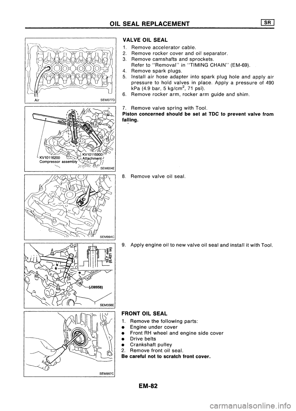
OILSEAL REPLACEMENT
VALVE OILSEAL
1. Remove accelerator cable.
2. Remove rockercoverandoilseparator.
3. Remove camshafts andsprockets.
Refer to"Removal" in"TIMING CHAIN"(EM-69).
4. Remove sparkplugs.
5. Install airhose adapter intospark plugholeandapply air
pressure tohold valves inplace. Applyapressure of490
kPa (4.9bar, 5kg/cm
2,
71psi).
6. Remove rockerarm,rocker armguide andshim.
Air SEM077D
7.Remove valvespring withTool.
Piston concerned shouldbeset atTOe toprevent valvefrom
falling.
8. Remove valveoilseal.
9. Apply engine oiltonew valve oilseal andinstall itwith Tool.
FRONT OILSEAL
1. Remove thefollowing parts:
• Engine undercover
• Front RHwheel andengine sidecover
• Drive belts
• Crankshaft pulley
2. Remove frontoilseal.
Be careful nottoscratch frontcover.
SEM997C EM-82
Page 1487 of 1701
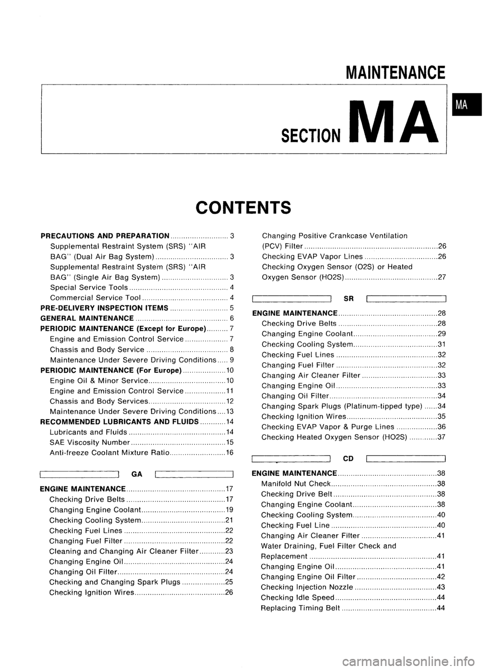
SECTION
CONTENTS
MAINTENANCE
MA
•
PRECAUTIONS ANDPREPARATION
3
Supplemental RestraintSystem(SRS)"AIR
BAG" (DualAirBag System) 3
Supplemental RestraintSystem(SRS)"AIR
BAG" (Single AirBag System) 3
Special Service Tools 4
Commercial ServiceTool 4
PRE-DELIVERY INSPECTIONITEMS
5
GENERAL MAINTENANCE 6
PERIODIC MAINTENANCE (Exceptfor
Europe) 7
Engine andEmission ControlService 7
Chassis andBody Service 8
Maintenance UnderSevere DrivingConditions 9
PERIODIC MAINTENANCE (ForEurope) 10
Engine Oil
&
Minor Service 10
Engine andEmission ControlService 11
Chassis andBody Services 12
Maintenance UnderSevere Driving Conditions 13
RECOMMENDED LUBRICANTSANDFLUIDS 14
Lubricants andFluids 14
SAE Viscosity Number 15
Anti-freeze CoolantMixtureRatio 16
~ --ll
GA
I I
ENGINE MAINTENANCE 17
Checking DriveBelts 17
Changing EngineCoolant... 19
Checking CoolingSystem 21
Checking FuelLines 22
Changing FuelFilter 22
Cleaning andChanging AirCleaner Filter 23
Changing EngineOil 24
Changing OilFilter 24
Checking andChanging SparkPlugs 25
Checking IgnitionWires 26Changing
PositiveCrankcase Ventilation
(PCV) Filter 26
Checking EVAPVapor Lines 26
Checking OxygenSensor(02S)orHeated
Oxygen Sensor(H02S) 27
~ --ll
SR
I I
ENGINE MAINTENANCE 28
Checking DriveBelts 28
Changing EngineCoolant... 29
Checking CoolingSystem 31
Checking FuelLines 32
Changing FuelFilter 32
Changing AirCleaner Filter 33
Changing EngineOil 33
Changing OilFilter 34
Changing SparkPlugs(Platinum-tipped type)34
Checking IgnitionWires 35
Checking EVAPVapor
&
Purge Lines 36
Checking HeatedOxygen Sensor(H02S) 37
~_~ ..-JI
CD
I I
ENGINE MAINTENANCE
38
Manifold NutCheck 38
Checking DriveBelt 38
Changing EngineCoolant. 38
Checking CoolingSystem .40
Checking FuelLine .40
Changing AirCleaner Filter 41
Water Draining, FuelFilter Check and
Replacement 41
Changing EngineOil .41
Changing EngineOilFilter 42
Checking InjectionNozzle 43
Checking IdleSpeed .44
Replacing TimingBelt 44
Page 1493 of 1701

PERIODICMAINTENANCE (ExceptforEurope)
The following tablesshowthenormal maintenance schedule.Depending uponweather andatmospheric
conditions, varyingroadsurfaces, individual drivinghabitsandvehicle usage,additional ormore fre-
quent maintenance mayberequired.
Periodic maintenance beyondthelast period shown onthe tables requires similarmaintenance .
Engine andEmission ControlService
•
Abbreviations: I
=
Inspect andcorrect orreplace asnecessary. R
MAINTENANCE OPERATION
Perform eitheratnumber ofkilometers (miles)
or months, whichever comestirst. km
x1,000
(Miles x1,000)
Months
Replace.
A
=
Adjust, C
=
Clean.
MAINTENANCE INTERVAL
10 20 3040
506070
80
Reference page
(6) (12) (18)
(24)(30)(36)(42)(48)
6 12 18
24
3036
42 48
Underhood andunder vehicle GA
SR
Intake
&
exhaust valveclearance (GA15DE
&
GA16DE engines) SeeNOTE (1)
EM41
-
Drive belts
II
MA 17
24
Engine anti-Ireeze coolant(Ethylene glycolbase)(LLC) RRMA 1929
Engine coolant (Softwater) RRR
R
R R
R
RMA
1929
Cooling system
I
I
I
I
MA 2131
Fuel lines
I
I
MA
22
32
Air cleaner filter(Drypaper type)*
CC
C RC CC RMA 23
-
Air cleaner filter(Viscous papertype)* R
RMA
2333
Engine oil(Use APISE,SF.SGorSH oil)*
R
RRRR R
RR
MA 24
33
Engine oilfilter* R
R R
R
R RRRMA
2433
Fuel filter* R
RMA
22
32
Spark plugs(except Platinum-tipped type) R
RMA
25
-
Spark plugs(platinum-tipped type) Replaceevery100,000 km(60.000 miles). MA
-
34
Ignition wires
I
I
MA
2635
PCV filter* R
RMA
26
-
Vapor lines
I
I
MA
26
36
(Heated) OxygenSensor
I
I
MA 2737
NOTE: (1)
If
valve noiseincreases, checkvalveclearance.
*
Maintenance itemswith
"*"
should beperformed morefrequently accordingto"Maintenance undersevere driv-
ing conditions".
MA-7
Page 1497 of 1701
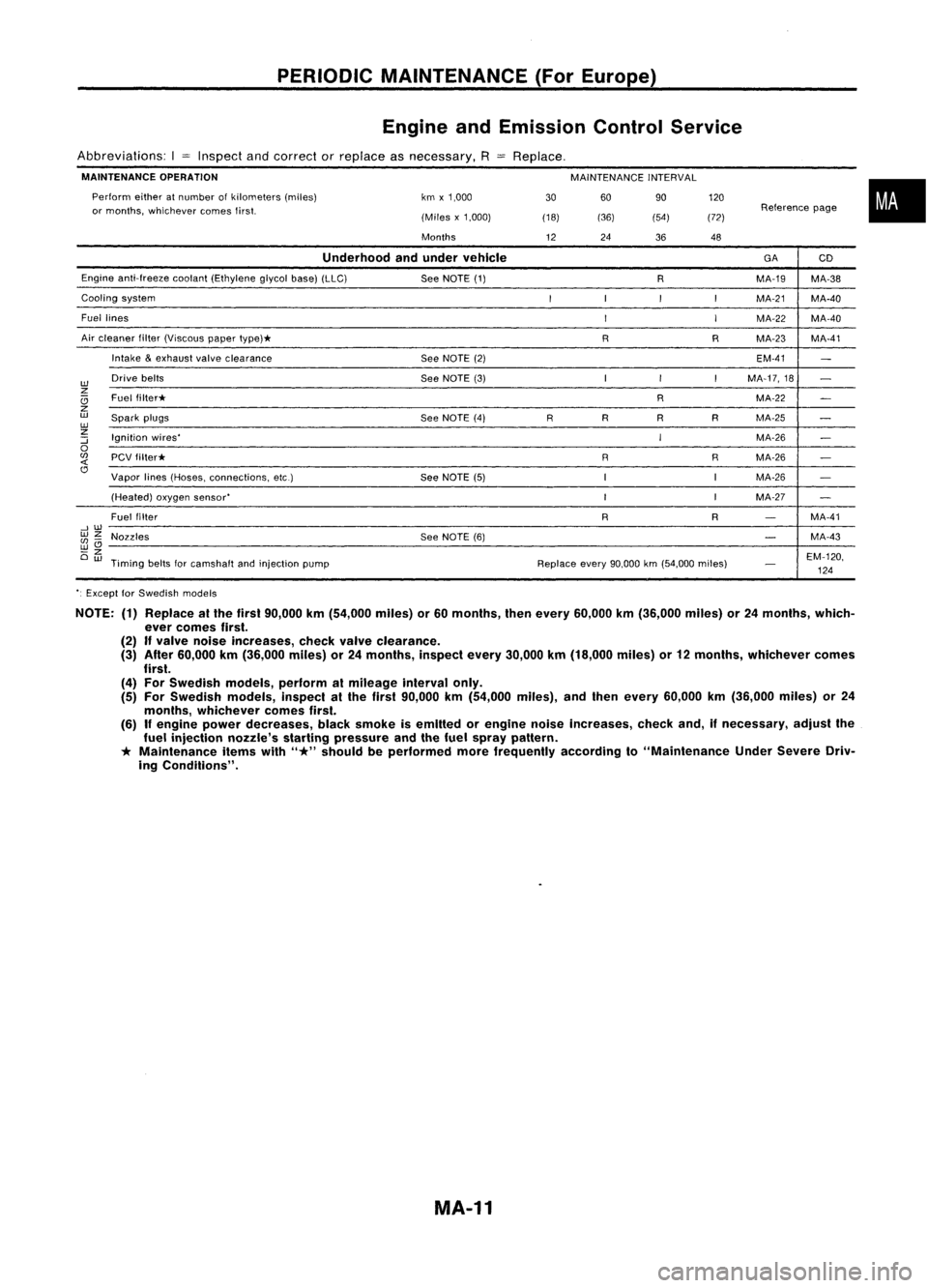
PERIODICMAINTENANCE (ForEurope)
Engine andEmission ControlService
Abbreviations: I
=
Inspect andcorrect orreplace asnecessary,
R
MAINTENANCE OPERATION
MAINTENANCEINTERVAL
60 90
(36) (54)
Perform
eitheratnumber ofkilometers (miles)
or months, whichever comesfirst. km
x1,000
(Miles x1,000)
Months
Replace,
30
(18)
12 24
36120
(72) 48
Reference
page
•
Underhood andunder vehicle
GA
CD
Engine anti-freeze cootant(Ethylene glycolbase)(LLC)
SeeNOTE (1)
RMA-19
MA-38
Cooling system
I
I
I
I
MA-21 MA-40
Fuel lines
I
I
MA-22
MA-40
Air cleaner filter(Viscous papertype)*
RRMA-23 MA-41
Intake
&
exhaust valveclearance
SeeNOTE (2) EM-41
-
w
Drive
belts
SeeNOTE (3) I
I
I
MA-17,18
-
z
Ci
Fuel
filter* RMA-22
-
z
w
Spark plugs
SeeNOTE (4)
RR
RRMA-25
-
w
z
Ignition wires'
IMA-26
:::;
-
0
(fJ
PCVfilter* RRMA-26
-
<{
Cl
Vapor lines(Hoses, connections, etc.)
SeeNOTE (5) IIMA-26
-
(Heated) oxygensensor'
I
IMA-27
-
Fuel filter
RR
-
MA-41
--,w
wz
Nozzles SeeNOTE (6)
-
MA-43
(fJ-
wCl
-z
EM-120,
Ow
Timing beltsforcamshalt andinjection pump Replaceevery90,000 km(54,000 miles)
-
124
'. Except forSwedish models
NOTE: (1)Replace atthe first 90,000 km(54,000 miles)or60 months, thenevery 60,000 km(36,000 miles)or24 months, which-
ever comes first.
(2)
If
valve noise Increases, checkvalveclearance.
(3) After 60,000 km(36,000 miles)or24 months, inspectevery30,000 km(18,000 miles)or12 months, whichever comes
first.
(4) For Swedish models,performalmileage intervalonly.
(5) For Swedish models,inspectalthe first 90,000 km(54,000 miles),andthen every 60,000 km(36,000 miles)or24
months, whichever comesfirst.
(6)
If
engine powerdecreases, blacksmoke isemitted orengine noiseincreases, checkand,ifnecessary, adjustthe
fuel injection nozzle'sstartingpressure andthefuel spray pattern.
*
Maintenance itemswith
"*"
should beperformed morefrequently accordingto"Maintenance UnderSevere Driv-
ing Conditions".
MA-11
Page 1511 of 1701
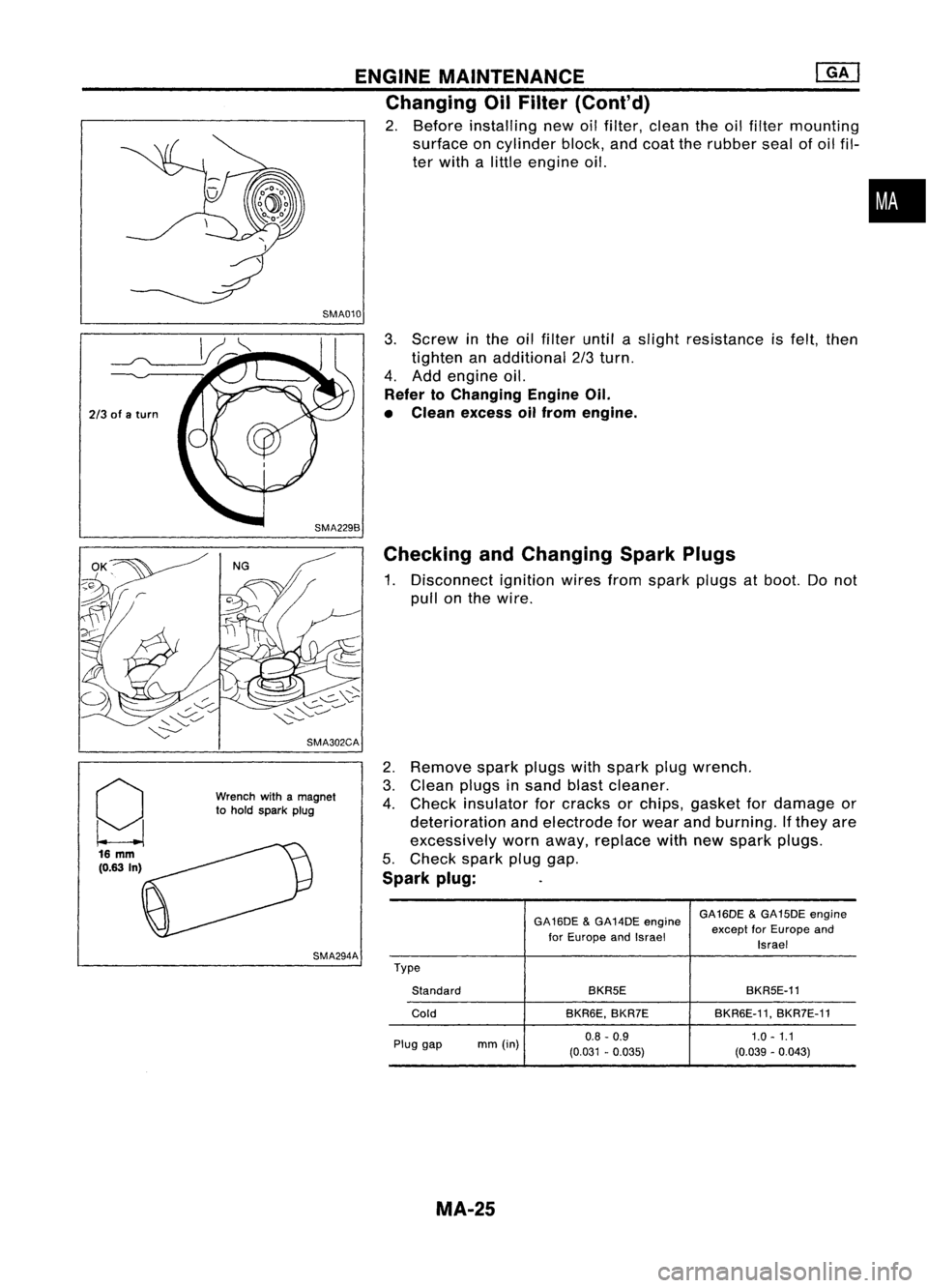
ENGINEMAINTENANCE ~
Changing OilFilter (Cont'd)
2. Before installing newoilfilter, clean theoilfilter mounting
surface oncylinder block,andcoat therubber sealofoil fil-
ter with alittle engine oil.
SMA010
•
2/3 ofaturn
g 16
mm
(0.63 In) SMA302CA
Wrench withamagnet
to hold spark plug
SMA294A
3.
Screw inthe oilfilter untilaslight resistance isfelt, then
tighten anadditional 2/3turn.
4. Add engine oil.
Refer toChanging EngineOil.
• Clean excess oilfrom engine.
Checking andChanging SparkPlugs
1. Disconnect ignitionwiresfromspark plugsatboot. Donot
pull onthe wire.
2. Remove sparkplugswithspark plugwrench.
3. Clean plugsinsand blastcleaner.
4. Check insulator forcracks orchips, gasket fordamage or
deterioration andelectrode forwear andburning. Ifthey are
excessively wornaway, replace withnewspark plugs.
5. Check sparkpluggap.
Spark plug:
GA16DE&GA14DE engine GA16DE
&GA15DE engine
for Europe andIsrael except
forEurope and
Israel
Type Standard BKR5E
BKR5E-11
Cold BKR6E,BKR7E BKR6E-11,
BKR7E-11
Plug gap mm(in) 0.8
-0.9 1.0-1.1
(0.031 -0.035) (0.039-0.043)
MA-25