steering NISSAN ALMERA N16 2001 Electronic Owners Manual
[x] Cancel search | Manufacturer: NISSAN, Model Year: 2001, Model line: ALMERA N16, Model: NISSAN ALMERA N16 2001Pages: 2493, PDF Size: 66.97 MB
Page 1816 of 2493
SST884C
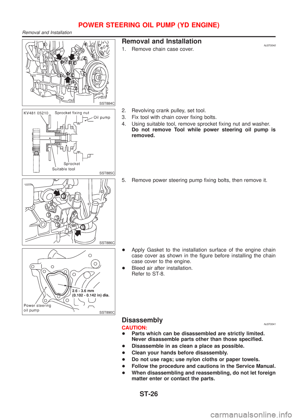
Removal and InstallationNJST00401. Remove chain case cover.
SST885C
2. Revolving crank pulley, set tool.
3. Fix tool with chain cover fixing bolts.
4. Using suitable tool, remove sprocket fixing nut and washer.
Do not remove Tool while power steering oil pump is
removed.
SST886C
5. Remove power steering pump fixing bolts, then remove it.
SST890C
+Apply Gasket to the installation surface of the engine chain
case cover as shown in the figure before installing the chain
case cover to the engine.
+Bleed air after installation.
Refer to ST-8.
DisassemblyNJST0041CAUTION:
+Parts which can be disassembled are strictly limited.
Never disassemble parts other than those specified.
+Disassemble in as clean a place as possible.
+Clean your hands before disassembly.
+Do not use rags; use nylon cloths or paper towels.
+Follow the procedure and cautions in the Service Manual.
+When disassembling and reassembling, do not let foreign
matter enter or contact the parts.
POWER STEERING OIL PUMP (YD ENGINE)
Removal and Installation
ST-26
Page 1817 of 2493

SST887C
+Remove rear bracket and rear body.
+Remove side plate seal, cam ring vane, rotor side and plate.
SST036A
+Remove inlet connector and outlet connector with spring.
Be careful not to drop the flow control valve.
Do not disassemble the flow control valve.
SST888C
+Remove oil seal
SST889C
+Remove snap ring, then draw drive shaft.
Be careful not to drop drive shaft.
InspectionNJST0042+If pulley is cracked or deformed, replace it.
+If an oil leak is found around pulley shaft oil seal, replace the
seal.
+If serration on pulley or pulley shaft is deformed or worn,
replace it.
POWER STEERING OIL PUMP (YD ENGINE)
Disassembly (Cont'd)
ST-27
Page 1818 of 2493
SST038A
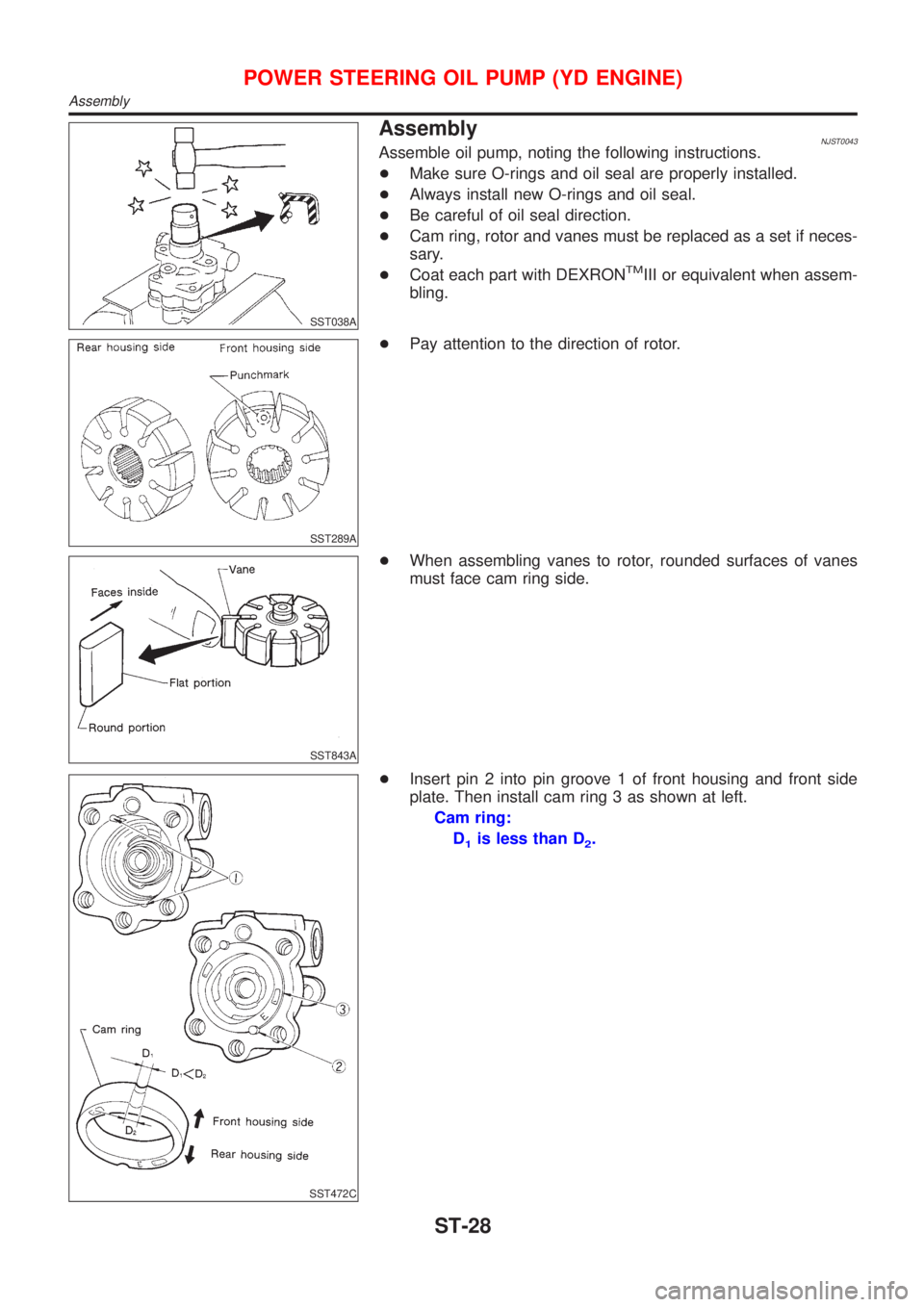
AssemblyNJST0043Assemble oil pump, noting the following instructions.
+Make sure O-rings and oil seal are properly installed.
+Always install new O-rings and oil seal.
+Be careful of oil seal direction.
+Cam ring, rotor and vanes must be replaced as a set if neces-
sary.
+Coat each part with DEXRON
TMIII or equivalent when assem-
bling.
SST289A
+Pay attention to the direction of rotor.
SST843A
+When assembling vanes to rotor, rounded surfaces of vanes
must face cam ring side.
SST472C
+Insert pin 2 into pin groove 1 of front housing and front side
plate. Then install cam ring 3 as shown at left.
Cam ring:
D
1is less than D2.
POWER STEERING OIL PUMP (YD ENGINE)
Assembly
ST-28
Page 1819 of 2493
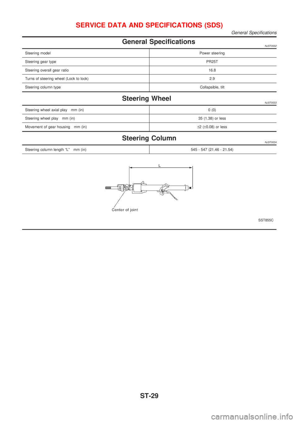
General SpecificationsNJST0032
Steering modelPower steering
Steering gear typePR25T
Steering overall gear ratio16.8
Turns of steering wheel (Lock to lock)2.9
Steering column typeCollapsible, tilt
Steering WheelNJST0033
Steering wheel axial play mm (in)0 (0)
Steering wheel play mm (in)35 (1.38) or less
Movement of gear housing mm (in)±2(±0.08) or less
Steering ColumnNJST0034
Steering column length ªLº mm (in) 545 - 547 (21.46 - 21.54)
SST855C
SERVICE DATA AND SPECIFICATIONS (SDS)
General Specifications
ST-29
Page 1820 of 2493
Steering Gear and LinkageNJST0035
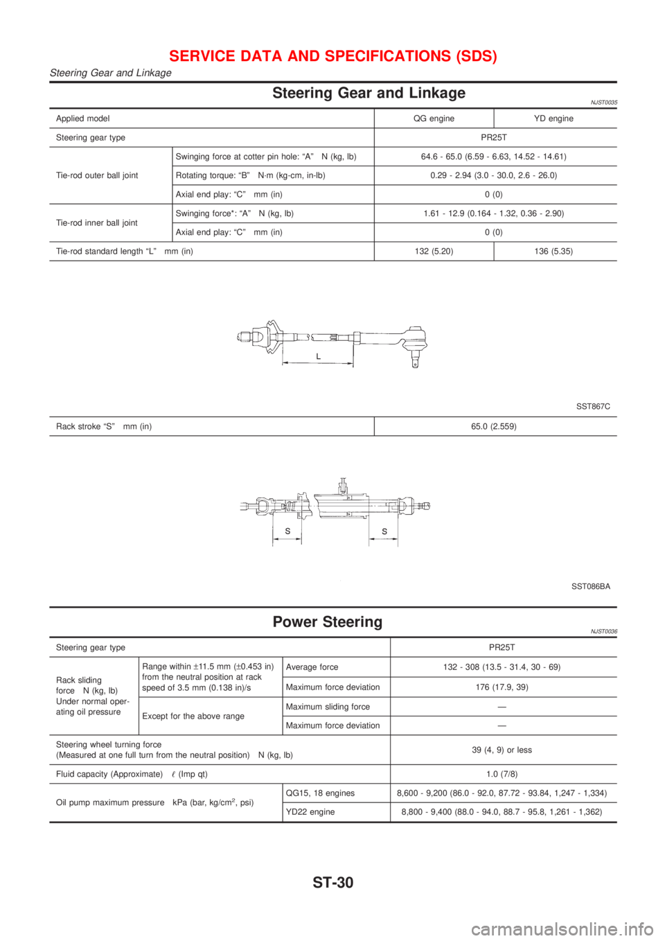
Applied modelQG engine YD engine
Steering gear typePR25T
Tie-rod outer ball jointSwinging force at cotter pin hole: ªAº N (kg, lb) 64.6 - 65.0 (6.59 - 6.63, 14.52 - 14.61)
Rotating torque: ªBº N´m (kg-cm, in-lb) 0.29 - 2.94 (3.0 - 30.0, 2.6 - 26.0)
Axial end play: ªCº mm (in) 0 (0)
Tie-rod inner ball jointSwinging force*: ªAº N (kg, lb) 1.61 - 12.9 (0.164 - 1.32, 0.36 - 2.90)
Axial end play: ªCº mm (in) 0 (0)
Tie-rod standard length ªLº mm (in) 132 (5.20) 136 (5.35)
SST867C
Rack stroke ªSº mm (in)65.0 (2.559)
SST086BA
Power SteeringNJST0036
Steering gear typePR25T
Rack sliding
force N (kg, lb)
Under normal oper-
ating oil pressureRange within±11.5 mm (±0.453 in)
from the neutral position at rack
speed of 3.5 mm (0.138 in)/sAverage force 132 - 308 (13.5 - 31.4, 30 - 69)
Maximum force deviation 176 (17.9, 39)
Except for the above rangeMaximum sliding force Ð
Maximum force deviation Ð
Steering wheel turning force
(Measured at one full turn from the neutral position) N (kg, lb)39 (4, 9) or less
Fluid capacity (Approximate)!(Imp qt)1.0 (7/8)
Oil pump maximum pressure kPa (bar, kg/cm
2, psi)QG15, 18 engines 8,600 - 9,200 (86.0 - 92.0, 87.72 - 93.84, 1,247 - 1,334)
YD22 engine 8,800 - 9,400 (88.0 - 94.0, 88.7 - 95.8, 1,261 - 1,362)
SERVICE DATA AND SPECIFICATIONS (SDS)
Steering Gear and Linkage
ST-30
Page 1821 of 2493
RESTRAINT SYSTEM
SECTION
RS
CONTENTS
SEAT BELTS...................................................................3
Precautions ..................................................................3
SUPPLEMENTAL RESTRAINT SYSTEM (SRS)
²AIR BAG²AND²SEAT BELT PRE-TENSIONER²
........3
PRECAUTION FOR SEAT BELT SERVICE..................3
Maintenance ................................................................4
Front Seat Belt.............................................................5
REMOVAL AND INSTALLATION/4-DOOR SEDAN.......5
REMOVAL AND INSTALLATION/5-DOOR
HATCHBACK
.............................................................7
REMOVAL AND INSTALLATION/3-DOOR
HATCHBACK
.............................................................9
Rear Seat Belt ........................................................... 11
REMOVAL AND INSTALLATION/4-DOOR SEDAN
WITH 2-POINT TYPE REAR CENTER SEAT BELT
.... 11
REMOVAL AND INSTALLATION/4-DOOR SEDAN
WITH 3-POINT TYPE REAR CENTER SEAT BELT
....13
REMOVAL AND INSTALLATION/HATCHBACK
WITH 3-POINT TYPE REAR CENTER SEAT
.............15
ISO Fix Child Restraint Anchor .................................18
REMOVAL AND INSTALLATION...............................18
Tether Anchor Plate ...................................................19
REMOVAL AND INSTALLATION...............................19
SUPPLEMENTAL RESTRAINT SYSTEM (SRS).........20
Precautions ................................................................20
SUPPLEMENTAL RESTRAINT SYSTEM (SRS)
²AIR BAG²AND²SEAT BELT PRE-TENSIONER²
......20
PRECAUTIONS FOR SRS²AIR BAG²AND²SEAT
BELT PRE-TENSIONER²SERVICE
...........................20
WIRING DIAGRAMS AND TROUBLE DIAGNOSIS.....20
Preparation ................................................................21
SPECIAL SERVICE TOOLS......................................21
COMMERCIAL SERVICE TOOL................................22
SRS Configuration .....................................................22
Seat Belt Pre-tensioner with Load Limiter.................23
Built-in Type Side Air Bag..........................................23
SRS Component Parts Location ...............................24
Maintenance Items ....................................................25
Diagnosis Sensor Unit ...............................................26
REMOVAL AND INSTALLATION...............................26
Front Seat Belt Pre-tensioner ....................................27
REMOVAL AND INSTALLATION...............................27
Side Air Bag (Satellite) Sensor ..................................27
REMOVAL AND INSTALLATION...............................27
Driver Air Bag Module and Spiral Cable ...................29
REMOVAL AND INSTALLATION/WITH 4-SPOKE
STEERING WHEEL
.................................................29
REMOVAL...............................................................29
INSTALLATION........................................................31
Front Passenger Air Bag Module ..............................32
REMOVAL...............................................................32
INSTALLATION........................................................33
Front Side Air Bag Module ........................................33
REMOVAL...............................................................33
INSTALLATION........................................................34
Disposal of Air Bag Module and Seat Belt Pre-
tensioner ....................................................................35
CHECKING DEPLOYMENT TOOL.............................35
DEPLOYMENT PROCEDURES FOR AIR BAG
MODULE (OUTSIDE OF VEHICLE)
...........................36
DEPLOYMENT PROCEDURES FOR SEAT BELT
PRE-TENSIONER (OUTSIDE OF VEHICLE)
..............39
DEPLOYMENT OF AIR BAG MODULE AND SEAT
BELT PRE-TENSIONER WHILE MOUNTED IN
VEHICLE
.................................................................39
DISPOSING OF AIR BAG MODULE AND SEAT
BELT PRE-TENSIONER
...........................................40
Trouble Diagnoses Introduction.................................41
DIAGNOSIS FUNCTION...........................................41
DIAGNOSIS MODE FOR CONSULT-II.......................41
HOW TO CHANGE SELF-DIAGNOSIS MODE
WITH CONSULT-II
...................................................42
HOW TO CHANGE SELF-DIAGNOSIS MODE
WITHOUT CONSULT-II
............................................42
HOW TO ERASE SELF-DIAGNOSIS RESULTS.........43
How to Perform Trouble Diagnoses for Quick
and Accurate Repair ..................................................44
INFORMATION FROM CUSTOMER..........................44
PRELIMINARY CHECK............................................44
WORK FLOW..........................................................45
Wiring Diagram - SRS -.............................................46
SEDAN MODELS.....................................................47
Page 1845 of 2493
SRS797-A
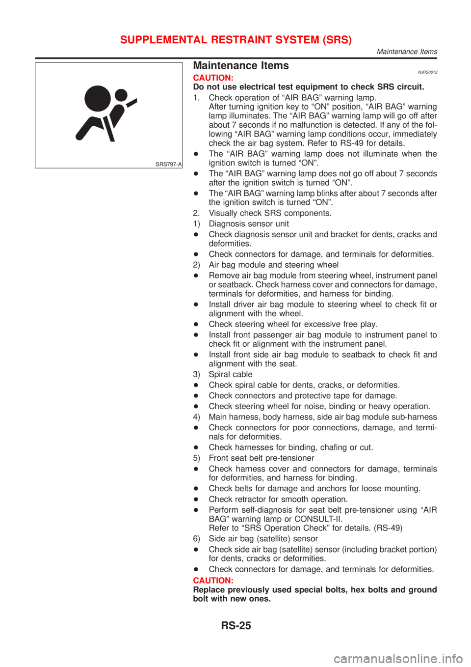
Maintenance ItemsNJRS0012CAUTION:
Do not use electrical test equipment to check SRS circuit.
1. Check operation of ªAIR BAGº warning lamp.
After turning ignition key to ªONº position, ªAIR BAGº warning
lamp illuminates. The ªAIR BAGº warning lamp will go off after
about 7 seconds if no malfunction is detected. If any of the fol-
lowing ªAIR BAGº warning lamp conditions occur, immediately
check the air bag system. Refer to RS-49 for details.
+The ªAIR BAGº warning lamp does not illuminate when the
ignition switch is turned ªONº.
+The ªAIR BAGº warning lamp does not go off about 7 seconds
after the ignition switch is turned ªONº.
+The ªAIR BAGº warning lamp blinks after about 7 seconds after
the ignition switch is turned ªONº.
2. Visually check SRS components.
1) Diagnosis sensor unit
+Check diagnosis sensor unit and bracket for dents, cracks and
deformities.
+Check connectors for damage, and terminals for deformities.
2) Air bag module and steering wheel
+Remove air bag module from steering wheel, instrument panel
or seatback. Check harness cover and connectors for damage,
terminals for deformities, and harness for binding.
+Install driver air bag module to steering wheel to check fit or
alignment with the wheel.
+Check steering wheel for excessive free play.
+Install front passenger air bag module to instrument panel to
check fit or alignment with the instrument panel.
+Install front side air bag module to seatback to check fit and
alignment with the seat.
3) Spiral cable
+Check spiral cable for dents, cracks, or deformities.
+Check connectors and protective tape for damage.
+Check steering wheel for noise, binding or heavy operation.
4) Main harness, body harness, side air bag module sub-harness
+Check connectors for poor connections, damage, and termi-
nals for deformities.
+Check harnesses for binding, chafing or cut.
5) Front seat belt pre-tensioner
+Check harness cover and connectors for damage, terminals
for deformities, and harness for binding.
+Check belts for damage and anchors for loose mounting.
+Check retractor for smooth operation.
+Perform self-diagnosis for seat belt pre-tensioner using ªAIR
BAGº warning lamp or CONSULT-II.
Refer to ªSRS Operation Checkº for details. (RS-49)
6) Side air bag (satellite) sensor
+Check side air bag (satellite) sensor (including bracket portion)
for dents, cracks or deformities.
+Check connectors for damage, and terminals for deformities.
CAUTION:
Replace previously used special bolts, hex bolts and ground
bolt with new ones.
SUPPLEMENTAL RESTRAINT SYSTEM (SRS)
Maintenance Items
RS-25
Page 1849 of 2493
Driver Air Bag Module and Spiral Cable
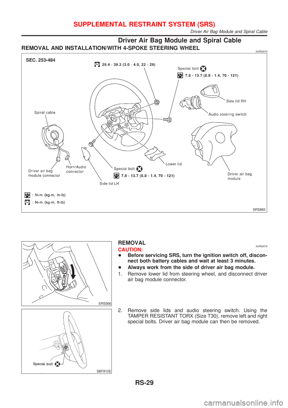
REMOVAL AND INSTALLATION/WITH 4-SPOKE STEERING WHEELNJRS0015
SRS865
SRS566
REMOVALNJRS0016CAUTION:
+Before servicing SRS, turn the ignition switch off, discon-
nect both battery cables and wait at least 3 minutes.
+Always work from the side of driver air bag module.
1. Remove lower lid from steering wheel, and disconnect driver
air bag module connector.
SBF812E
2. Remove side lids and audio steering switch. Using the
TAMPER RESISTANT TORX (Size T30), remove left and right
special bolts. Driver air bag module can then be removed.
SUPPLEMENTAL RESTRAINT SYSTEM (SRS)
Driver Air Bag Module and Spiral Cable
RS-29
Page 1850 of 2493
SRS443
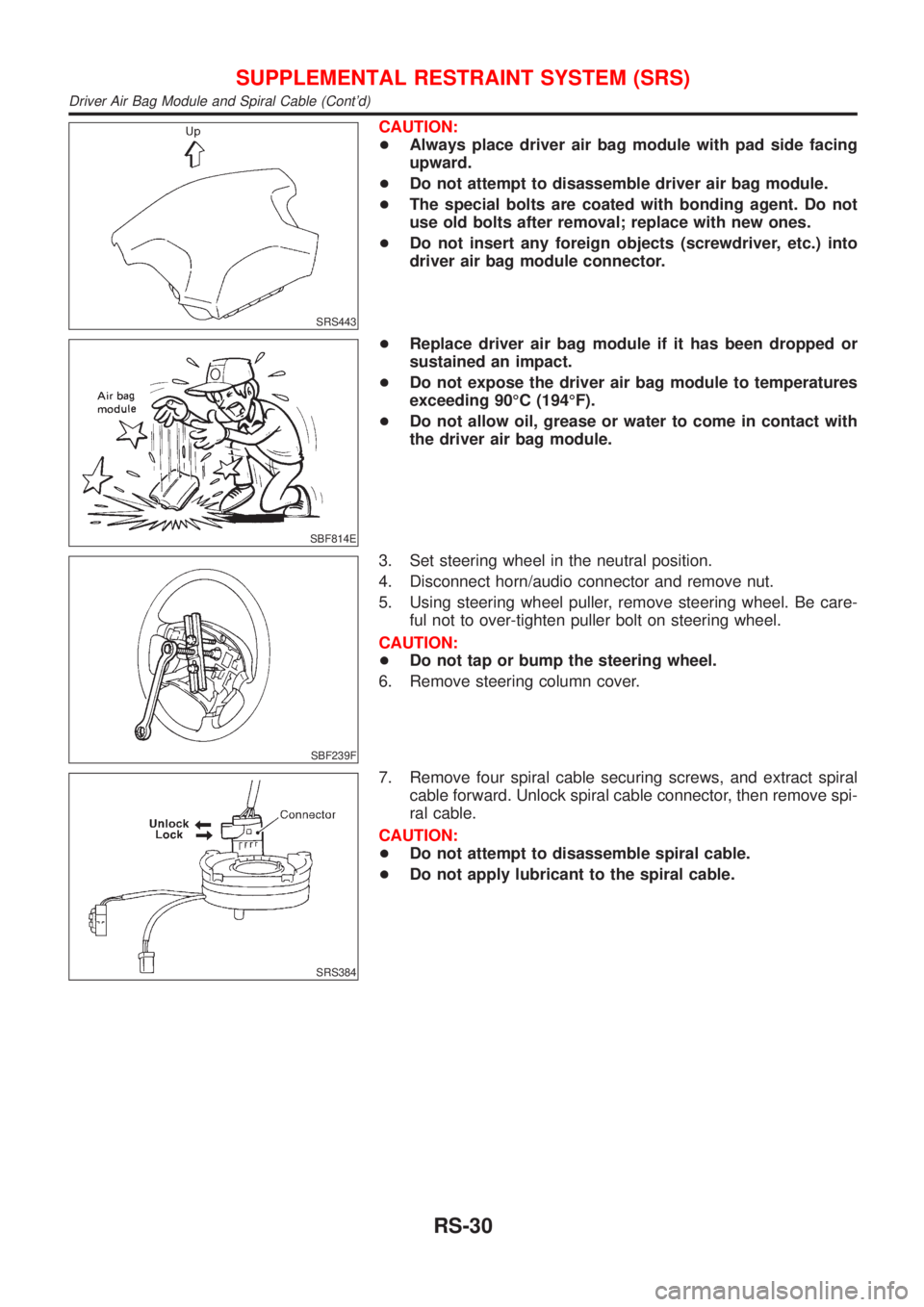
CAUTION:
+Always place driver air bag module with pad side facing
upward.
+Do not attempt to disassemble driver air bag module.
+The special bolts are coated with bonding agent. Do not
use old bolts after removal; replace with new ones.
+Do not insert any foreign objects (screwdriver, etc.) into
driver air bag module connector.
SBF814E
+Replace driver air bag module if it has been dropped or
sustained an impact.
+Do not expose the driver air bag module to temperatures
exceeding 90ÉC (194ÉF).
+Do not allow oil, grease or water to come in contact with
the driver air bag module.
SBF239F
3. Set steering wheel in the neutral position.
4. Disconnect horn/audio connector and remove nut.
5. Using steering wheel puller, remove steering wheel. Be care-
ful not to over-tighten puller bolt on steering wheel.
CAUTION:
+Do not tap or bump the steering wheel.
6. Remove steering column cover.
SRS384
7. Remove four spiral cable securing screws, and extract spiral
cable forward. Unlock spiral cable connector, then remove spi-
ral cable.
CAUTION:
+Do not attempt to disassemble spiral cable.
+Do not apply lubricant to the spiral cable.
SUPPLEMENTAL RESTRAINT SYSTEM (SRS)
Driver Air Bag Module and Spiral Cable (Cont'd)
RS-30
Page 1851 of 2493
NRS121
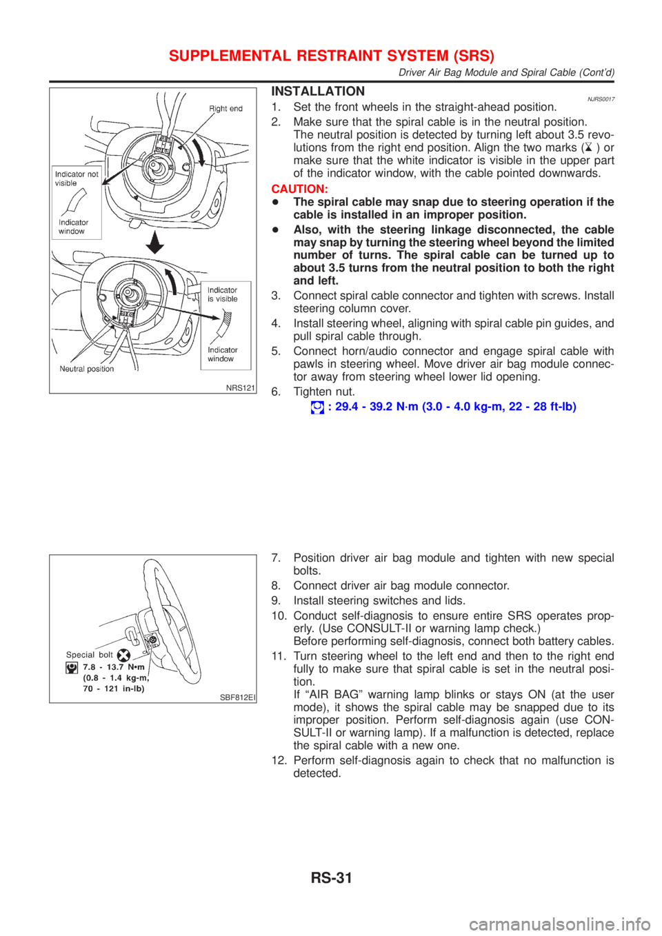
INSTALLATIONNJRS00171. Set the front wheels in the straight-ahead position.
2. Make sure that the spiral cable is in the neutral position.
The neutral position is detected by turning left about 3.5 revo-
lutions from the right end position. Align the two marks (
)or
make sure that the white indicator is visible in the upper part
of the indicator window, with the cable pointed downwards.
CAUTION:
+The spiral cable may snap due to steering operation if the
cable is installed in an improper position.
+Also, with the steering linkage disconnected, the cable
may snap by turning the steering wheel beyond the limited
number of turns. The spiral cable can be turned up to
about 3.5 turns from the neutral position to both the right
and left.
3. Connect spiral cable connector and tighten with screws. Install
steering column cover.
4. Install steering wheel, aligning with spiral cable pin guides, and
pull spiral cable through.
5. Connect horn/audio connector and engage spiral cable with
pawls in steering wheel. Move driver air bag module connec-
tor away from steering wheel lower lid opening.
6. Tighten nut.
: 29.4 - 39.2 N´m (3.0 - 4.0 kg-m, 22 - 28 ft-lb)
SBF812EI
7. Position driver air bag module and tighten with new special
bolts.
8. Connect driver air bag module connector.
9. Install steering switches and lids.
10. Conduct self-diagnosis to ensure entire SRS operates prop-
erly. (Use CONSULT-II or warning lamp check.)
Before performing self-diagnosis, connect both battery cables.
11. Turn steering wheel to the left end and then to the right end
fully to make sure that spiral cable is set in the neutral posi-
tion.
If ªAIR BAGº warning lamp blinks or stays ON (at the user
mode), it shows the spiral cable may be snapped due to its
improper position. Perform self-diagnosis again (use CON-
SULT-II or warning lamp). If a malfunction is detected, replace
the spiral cable with a new one.
12. Perform self-diagnosis again to check that no malfunction is
detected.
SUPPLEMENTAL RESTRAINT SYSTEM (SRS)
Driver Air Bag Module and Spiral Cable (Cont'd)
RS-31