headlamp NISSAN ALMERA N16 2001 Electronic User Guide
[x] Cancel search | Manufacturer: NISSAN, Model Year: 2001, Model line: ALMERA N16, Model: NISSAN ALMERA N16 2001Pages: 2493, PDF Size: 66.97 MB
Page 832 of 2493
Basic InspectionNJEC0632Precaution:
Perform Basic Inspection without electrical or mechanical
loads applied;
+Headlamp switch is OFF,
+On vehicles equipped with daytime light systems, set
lighting switch to the 1st position to light only small
lamps.
+Air conditioner switch is OFF,
+Rear defogger switch is OFF,
+Steering wheel is in the straight-ahead position, etc.
1 INSPECTION START
1. Check service records for any recent repairs that may indicate a related problem.
2. Check the current need for scheduled maintenance, especially for fuel filter and air cleaner filter. Refer to MA-4, ªPeri-
odic Maintenanceº.
3. Open engine hood and check the following:
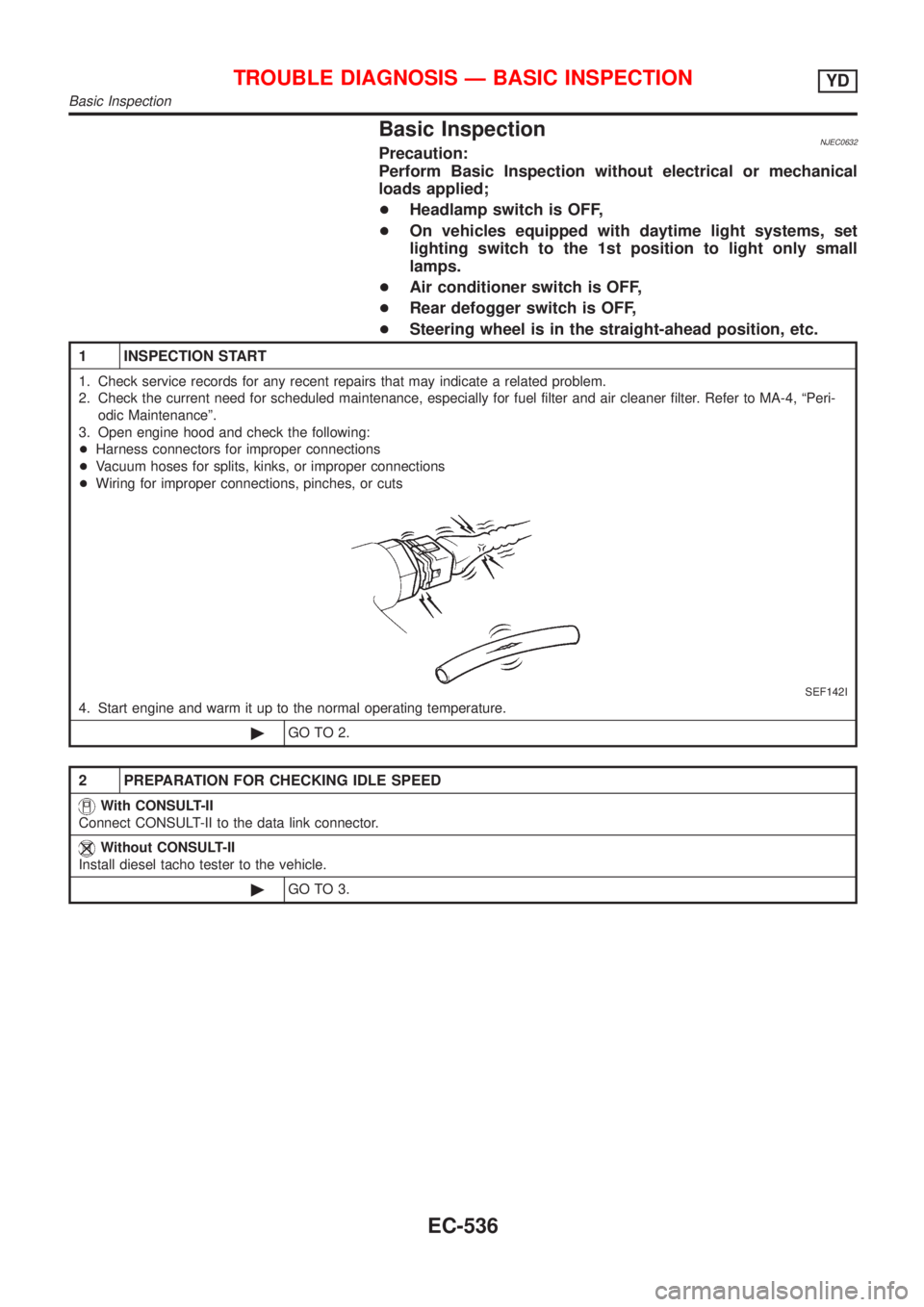
+Harness connectors for improper connections
+Vacuum hoses for splits, kinks, or improper connections
+Wiring for improper connections, pinches, or cuts
SEF142I
4. Start engine and warm it up to the normal operating temperature.
©GO TO 2.
2 PREPARATION FOR CHECKING IDLE SPEED
With CONSULT-II
Connect CONSULT-II to the data link connector.
Without CONSULT-II
Install diesel tacho tester to the vehicle.
©GO TO 3.
TROUBLE DIAGNOSIS Ð BASIC INSPECTIONYD
Basic Inspection
EC-536
Page 1781 of 2493
5. Pedal Vibration and Noise=NJBR0108
1 INSPECTION START
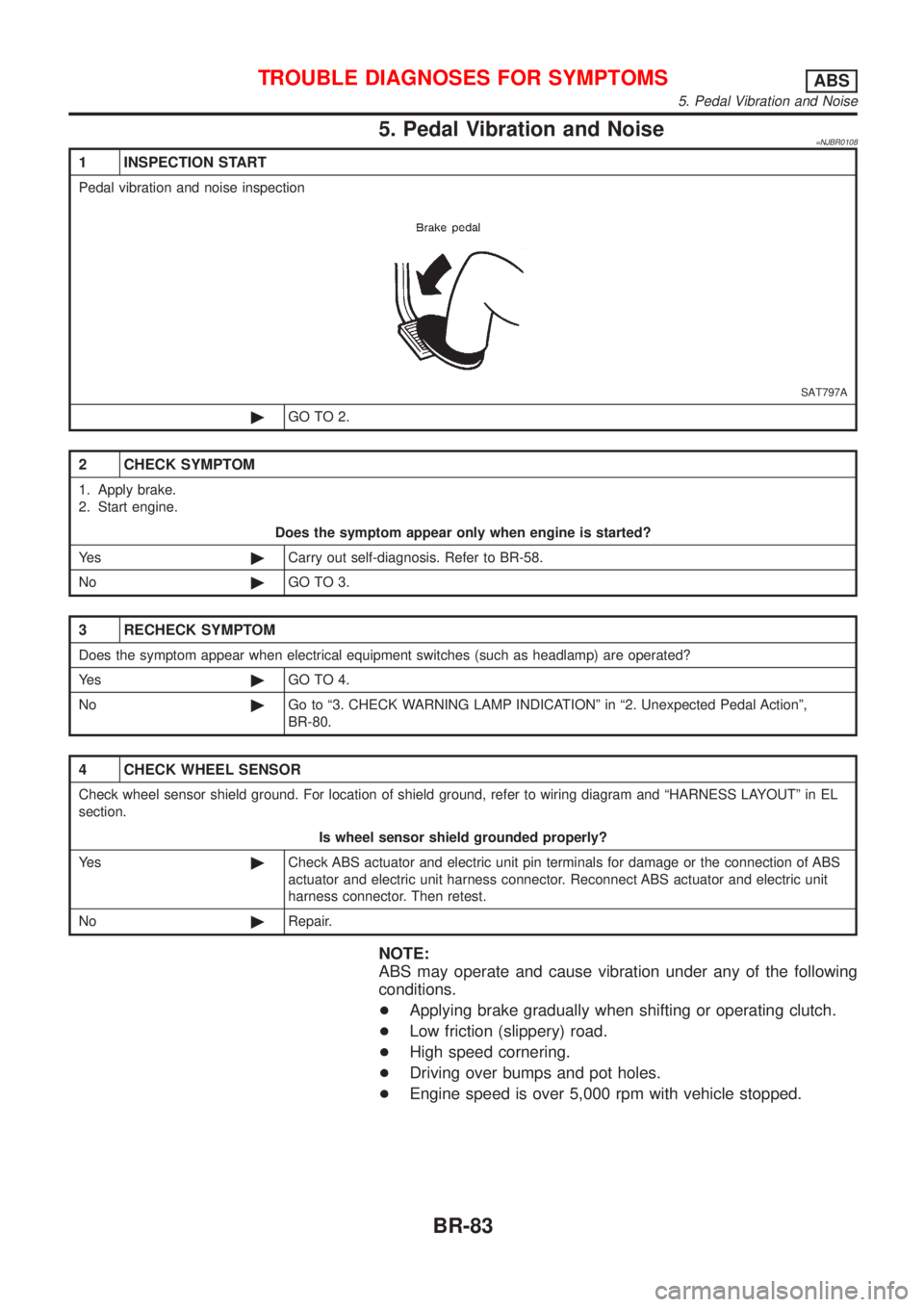
Pedal vibration and noise inspection
SAT797A
©GO TO 2.
2 CHECK SYMPTOM
1. Apply brake.
2. Start engine.
Does the symptom appear only when engine is started?
Ye s©Carry out self-diagnosis. Refer to BR-58.
No©GO TO 3.
3 RECHECK SYMPTOM
Does the symptom appear when electrical equipment switches (such as headlamp) are operated?
Ye s©GO TO 4.
No©Go to ª3. CHECK WARNING LAMP INDICATIONº in ª2. Unexpected Pedal Actionº,
BR-80.
4 CHECK WHEEL SENSOR
Check wheel sensor shield ground. For location of shield ground, refer to wiring diagram and ªHARNESS LAYOUTº in EL
section.
Is wheel sensor shield grounded properly?
Ye s©Check ABS actuator and electric unit pin terminals for damage or the connection of ABS
actuator and electric unit harness connector. Reconnect ABS actuator and electric unit
harness connector. Then retest.
No©Repair.
NOTE:
ABS may operate and cause vibration under any of the following
conditions.
+Applying brake gradually when shifting or operating clutch.
+Low friction (slippery) road.
+High speed cornering.
+Driving over bumps and pot holes.
+Engine speed is over 5,000 rpm with vehicle stopped.
TROUBLE DIAGNOSES FOR SYMPTOMSABS
5. Pedal Vibration and Noise
BR-83
Page 1901 of 2493
Removal and InstallationNJBT0004+When removing or installing hood, place a cloth or other padding on hood. This prevents vehicle body from
being scratched.
+Bumper fascia is made of plastic. Do not use excessive force and be sure to keep oil away from it.
+Hood adjustment: Adjust at hinge portion.
+Hood lock adjustment: After adjusting, check hood lock control operation. Apply a coat of grease to hood
locks engaging mechanism.
+Hood opener: Do not attempt to bend cable forcibly. Doing so increases effort required to unlock hood.
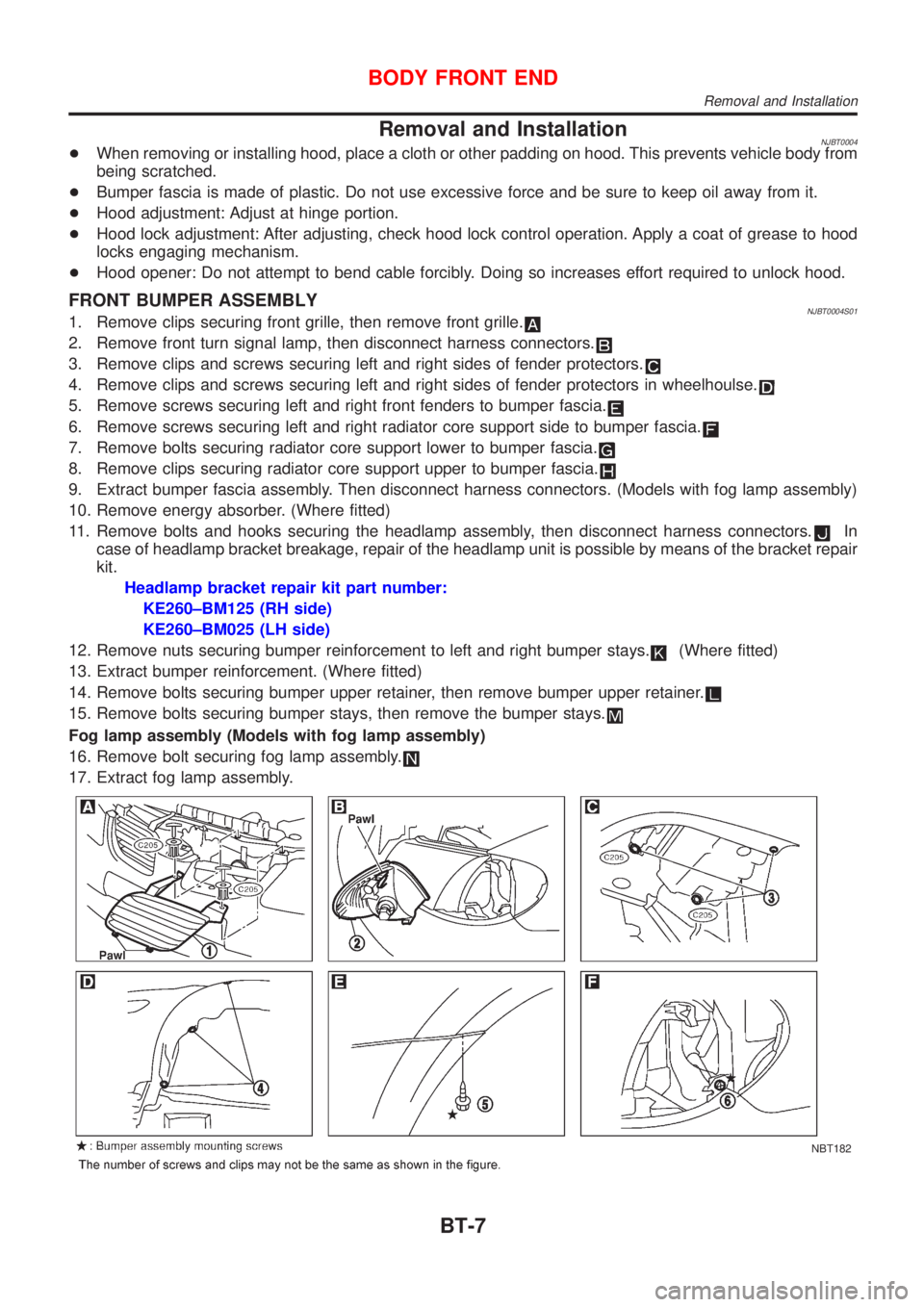
FRONT BUMPER ASSEMBLYNJBT0004S011. Remove clips securing front grille, then remove front grille.
2. Remove front turn signal lamp, then disconnect harness connectors.
3. Remove clips and screws securing left and right sides of fender protectors.
4. Remove clips and screws securing left and right sides of fender protectors in wheelhoulse.
5. Remove screws securing left and right front fenders to bumper fascia.
6. Remove screws securing left and right radiator core support side to bumper fascia.
7. Remove bolts securing radiator core support lower to bumper fascia.
8. Remove clips securing radiator core support upper to bumper fascia.
9. Extract bumper fascia assembly. Then disconnect harness connectors. (Models with fog lamp assembly)
10. Remove energy absorber. (Where fitted)
11. Remove bolts and hooks securing the headlamp assembly, then disconnect harness connectors.
In
case of headlamp bracket breakage, repair of the headlamp unit is possible by means of the bracket repair
kit.
Headlamp bracket repair kit part number:
KE260±BM125 (RH side)
KE260±BM025 (LH side)
12. Remove nuts securing bumper reinforcement to left and right bumper stays.
(Where fitted)
13. Extract bumper reinforcement. (Where fitted)
14. Remove bolts securing bumper upper retainer, then remove bumper upper retainer.
15. Remove bolts securing bumper stays, then remove the bumper stays.
Fog lamp assembly (Models with fog lamp assembly)
16. Remove bolt securing fog lamp assembly.
17. Extract fog lamp assembly.
NBT182
BODY FRONT END
Removal and Installation
BT-7
Page 2113 of 2493
ELECTRICAL SYSTEM
SECTION
EL
CONTENTS
PRECAUTIONS...............................................................4
Supplemental Restraint System (SRS)²AIR
BAG²and²SEAT BELT PRE-TENSIONER²...............4
Wiring Diagrams and Trouble Diagnosis .....................4
HARNESS CONNECTOR................................................5
Description ...................................................................5
STANDARDIZED RELAY................................................7
Description ...................................................................7
POWER SUPPLY ROUTING...........................................9
Schematic ..................................................................10
Wiring Diagram - POWER - ......................................12
Inspection...................................................................22
GROUND........................................................................23
Ground Distribution ....................................................23
COMBINATION SWITCH..............................................37
Check .........................................................................37
Replacement ..............................................................38
STEERING SWITCH......................................................39
Check .........................................................................39
HEADLAMP...................................................................40
Wiring Diagram - H/LAMP -.......................................40
Trouble Diagnoses.....................................................41
Bulb Replacement .....................................................42
Aiming Adjustment .....................................................42
HEADLAMP - DAYTIME LIGHT SYSTEM -.................44
System Description ....................................................44
Schematic ..................................................................45
Wiring Diagram - DTRL - ...........................................46
Trouble Diagnoses.....................................................49
Bulb Replacement .....................................................49
Aiming Adjustment .....................................................50
HEADLAMP - HEADLAMP AIMING CONTROL -........51
Wiring Diagram - H/AIM - ..........................................51
PARKING, LICENSE AND TAIL LAMPS.....................53
Wiring Diagram - TAIL/L - ..........................................53
STOP LAMP..................................................................56
Wiring Diagram - STOP/L - .......................................56
BACK-UP LAMP............................................................58
Wiring Diagram - BACK/L - .......................................58FRONT FOG LAMP.......................................................60
Wiring Diagram - F/FOG - .........................................60
Bulb Replacement .....................................................61
Aiming Adjustment .....................................................62
REAR FOG LAMP.........................................................63
Wiring Diagram - R/FOG -.........................................63
TURN SIGNAL AND HAZARD WARNING LAMPS.....65
System Description ....................................................65
Schematic ..................................................................66
Wiring Diagram - TURN - ..........................................67
Trouble Diagnoses.....................................................70
ILLUMINATION..............................................................71
Schematic ..................................................................71
Wiring Diagram - ILL - ...............................................72
INTERIOR ROOM LAMP...............................................76
System Description/ With Interior Room Lamp
Timer ..........................................................................76
Wiring Diagram - ROOM/L -/ With Interior Room
Lamp Timer ................................................................78
Trouble Diagnoses/ With Interior Room Lamp
Timer ..........................................................................80
Wiring Diagram - ROOM/L -/ Without Timer .............86
SPOT AND TRUNK ROOM LAMPS.............................87
Wiring Diagram - INT/L - ...........................................87
METERS AND GAUGES...............................................89
Component Parts and Harness Connector
Location .....................................................................89
System Description ....................................................89
Combination Meter ....................................................91
Schematic ..................................................................92
Construction ...............................................................93
Wiring Diagram - METER - .......................................94
Combination Meter Self-Diagnosis ............................96
Trouble Diagnoses.....................................................99
Electrical Components Inspection ...........................106
WARNING LAMPS......................................................107
Schematic ................................................................107
Wiring Diagram - WARN - .......................................108
Electrical Components Inspection ........................... 112
Page 2114 of 2493
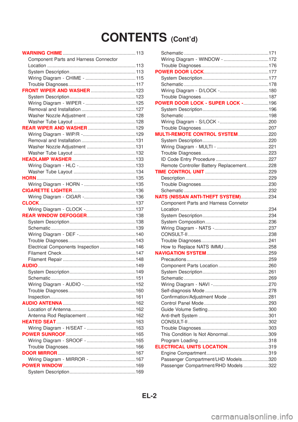
WARNING CHIME....................................................... 113
Component Parts and Harness Connector
Location ................................................................... 113
System Description .................................................. 113
Wiring Diagram - CHIME - ...................................... 115
Trouble Diagnoses................................................... 117
FRONT WIPER AND WASHER..................................123
System Description ..................................................123
Wiring Diagram - WIPER - ......................................125
Removal and Installation .........................................127
Washer Nozzle Adjustment .....................................128
Washer Tube Layout ...............................................128
REAR WIPER AND WASHER....................................129
Wiring Diagram - WIP/R -........................................129
Removal and Installation .........................................131
Washer Nozzle Adjustment .....................................131
Washer Tube Layout ...............................................132
HEADLAMP WASHER................................................133
Wiring Diagram - HLC - ...........................................133
Washer Tube Layout ...............................................134
HORN...........................................................................135
Wiring Diagram - HORN - .......................................135
CIGARETTE LIGHTER................................................136
Wiring Diagram - CIGAR -.......................................136
CLOCK.........................................................................137
Wiring Diagram - CLOCK -......................................137
REAR WINDOW DEFOGGER.....................................138
System Description ..................................................138
Schematic ................................................................139
Wiring Diagram - DEF - ...........................................140
Trouble Diagnoses...................................................143
Electrical Components Inspection ...........................146
Filament Check ........................................................147
Filament Repair .......................................................148
AUDIO..........................................................................149
System Description ..................................................149
Schematic ................................................................151
Wiring Diagram - AUDIO - .......................................152
Trouble Diagnoses...................................................160
Inspection.................................................................161
AUDIO ANTENNA.......................................................162
Location of Antenna .................................................162
Antenna Rod Replacement .....................................162
HEATED SEAT............................................................163
Wiring Diagram - H/SEAT - .....................................163
POWER SUNROOF.....................................................165
Wiring Diagram - SROOF - .....................................165
Trouble Diagnoses...................................................166
DOOR MIRROR...........................................................167
Wiring Diagram - MIRROR - ...................................167
POWER WINDOW.......................................................169
System Description ..................................................169Schematic ................................................................171
Wiring Diagram - WINDOW - ..................................172
Trouble Diagnoses...................................................176
POWER DOOR LOCK.................................................177
System Description ..................................................177
Schematic ................................................................178
Wiring Diagram - D/LOCK -.....................................180
Trouble Diagnoses...................................................187
POWER DOOR LOCK - SUPER LOCK -...................196
System Description ..................................................196
Schematic ................................................................198
Wiring Diagram - S/LOCK - .....................................200
Trouble Diagnoses...................................................207
MULTI-REMOTE CONTROL SYSTEM.......................220
System Description ..................................................220
Wiring Diagram - MULTI - .......................................221
Trouble Diagnoses...................................................223
ID Code Entry Procedure ........................................227
Remote Controller Battery Replacement.................228
TIME CONTROL UNIT................................................229
Description ...............................................................229
Trouble Diagnoses...................................................230
Schematic ................................................................232
NATS (NISSAN ANTI-THEFT SYSTEM).....................234
Component Parts and Harness Connetor
Location ...................................................................234
System Description ..................................................234
System Composition ................................................236
Wiring Diagram - NATS -.........................................237
CONSULT-II .............................................................238
Trouble Diagnoses...................................................241
How to Replace NATS IMMU ..................................258
NAVIGATION SYSTEM...............................................259
Precautions ..............................................................259
Component Parts Location ......................................260
System Description ..................................................261
Schematic ................................................................269
Wiring Diagram - NAVI - ..........................................270
Self-diagnosis Mode ................................................278
Confirmation/Adjustment Mode ...............................281
Control Panel Mode .................................................293
Guide Volume Setting ..............................................300
Anti-theft System .....................................................301
CONSULT-II .............................................................302
Trouble Diagnoses...................................................303
This Condition Is Not Abnormal...............................309
Program Loading .....................................................318
ELECTRICAL UNITS LOCATION...............................319
Engine Compartment ...............................................319
Passenger Compartment/LHD Models ....................320
Passenger Compartment/RHD Models ...................322
CONTENTS(Cont'd)
EL-2
Page 2115 of 2493
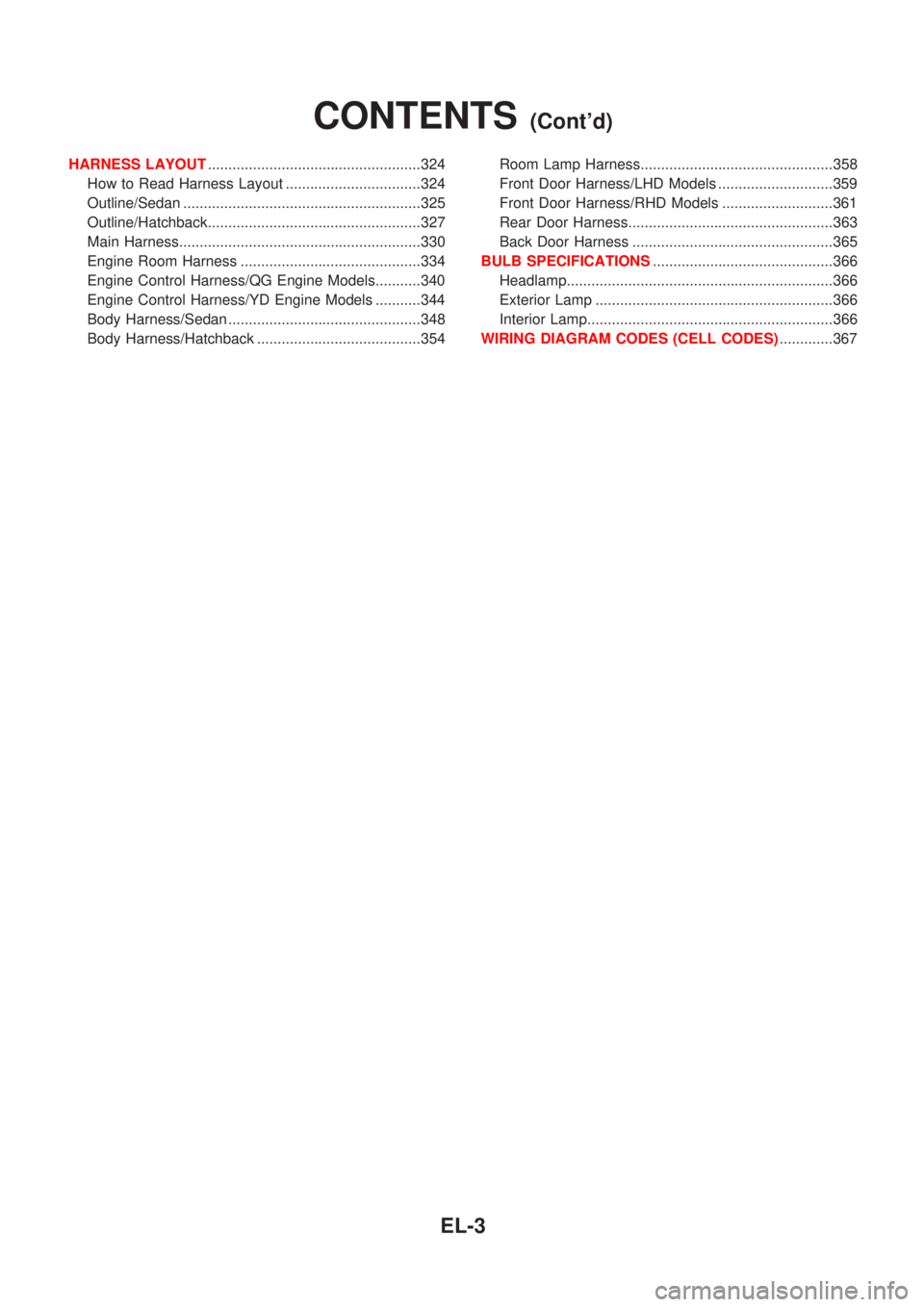
HARNESS LAYOUT....................................................324
How to Read Harness Layout .................................324
Outline/Sedan ..........................................................325
Outline/Hatchback....................................................327
Main Harness...........................................................330
Engine Room Harness ............................................334
Engine Control Harness/QG Engine Models...........340
Engine Control Harness/YD Engine Models ...........344
Body Harness/Sedan ...............................................348
Body Harness/Hatchback ........................................354Room Lamp Harness...............................................358
Front Door Harness/LHD Models ............................359
Front Door Harness/RHD Models ...........................361
Rear Door Harness..................................................363
Back Door Harness .................................................365
BULB SPECIFICATIONS............................................366
Headlamp.................................................................366
Exterior Lamp ..........................................................366
Interior Lamp............................................................366
WIRING DIAGRAM CODES (CELL CODES).............367
CONTENTS(Cont'd)
EL-3
Page 2152 of 2493
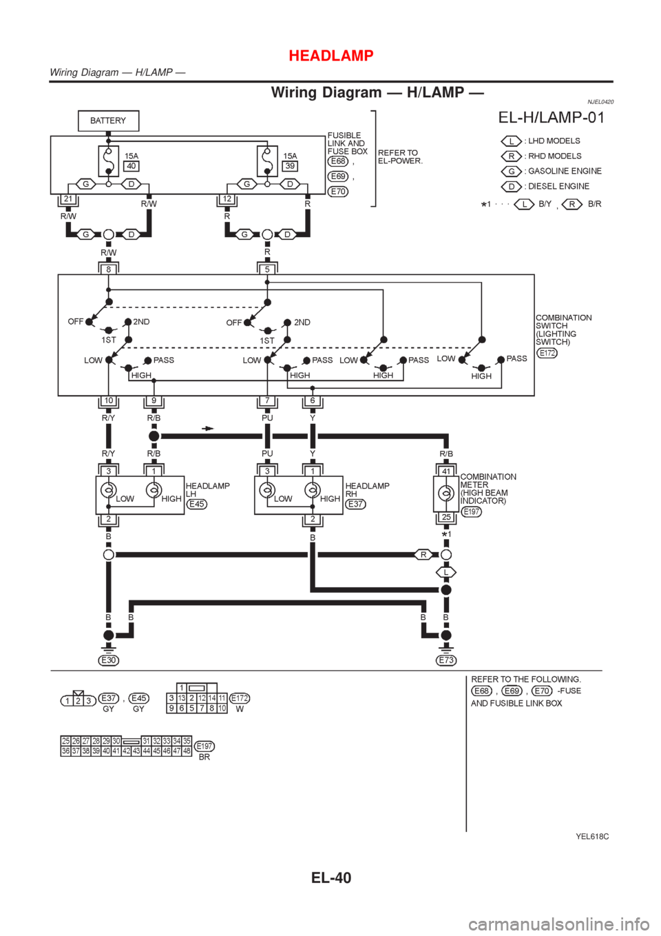
Wiring Diagram Ð H/LAMP ÐNJEL0420
YEL618C
HEADLAMP
Wiring Diagram Ð H/LAMP Ð
EL-40
Page 2153 of 2493
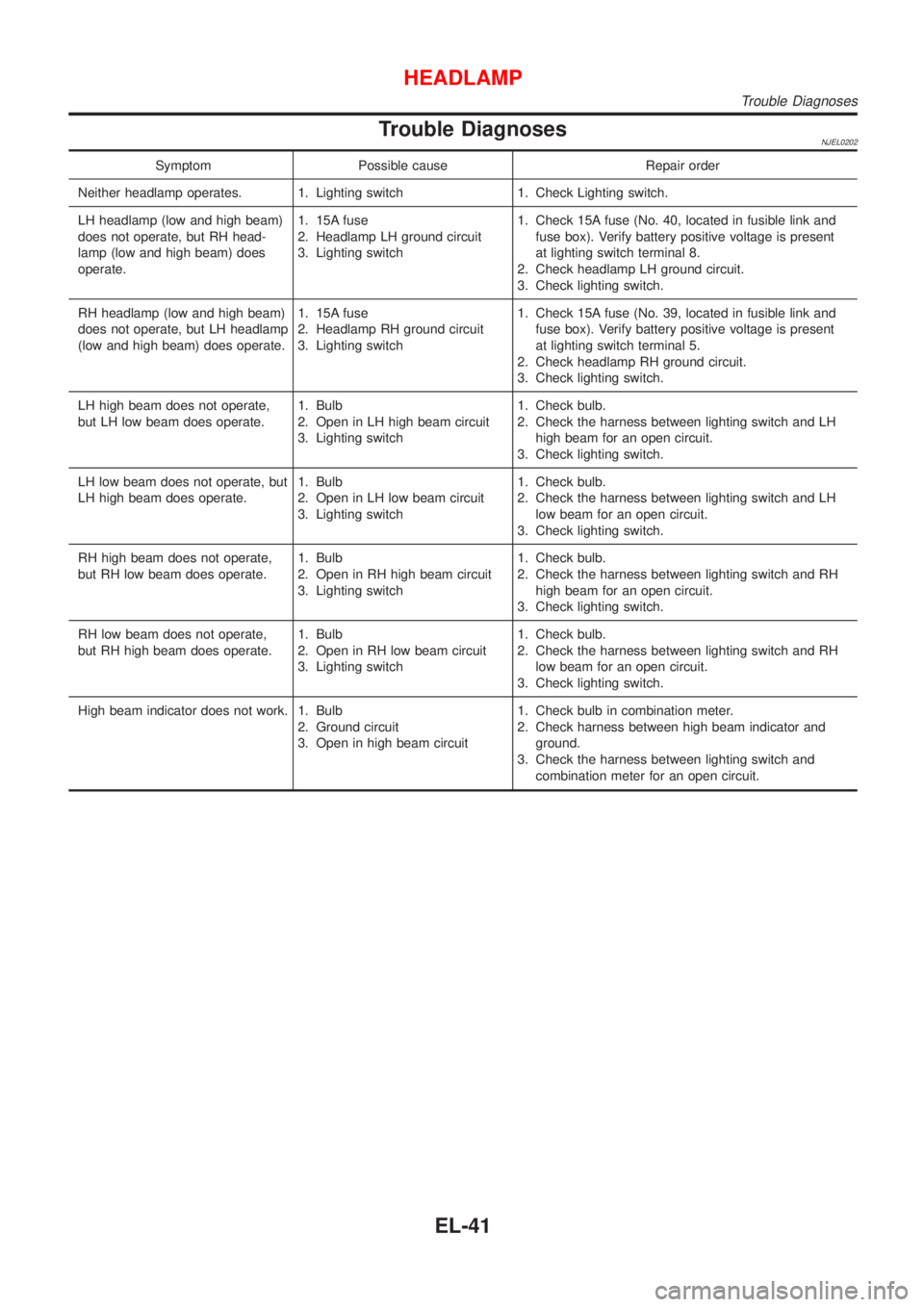
Trouble DiagnosesNJEL0202
Symptom Possible cause Repair order
Neither headlamp operates. 1. Lighting switch 1. Check Lighting switch.
LH headlamp (low and high beam)
does not operate, but RH head-
lamp (low and high beam) does
operate.1. 15A fuse
2. Headlamp LH ground circuit
3. Lighting switch1. Check 15A fuse (No. 40, located in fusible link and
fuse box). Verify battery positive voltage is present
at lighting switch terminal 8.
2. Check headlamp LH ground circuit.
3. Check lighting switch.
RH headlamp (low and high beam)
does not operate, but LH headlamp
(low and high beam) does operate.1. 15A fuse
2. Headlamp RH ground circuit
3. Lighting switch1. Check 15A fuse (No. 39, located in fusible link and
fuse box). Verify battery positive voltage is present
at lighting switch terminal 5.
2. Check headlamp RH ground circuit.
3. Check lighting switch.
LH high beam does not operate,
but LH low beam does operate.1. Bulb
2. Open in LH high beam circuit
3. Lighting switch1. Check bulb.
2. Check the harness between lighting switch and LH
high beam for an open circuit.
3. Check lighting switch.
LH low beam does not operate, but
LH high beam does operate.1. Bulb
2. Open in LH low beam circuit
3. Lighting switch1. Check bulb.
2. Check the harness between lighting switch and LH
low beam for an open circuit.
3. Check lighting switch.
RH high beam does not operate,
but RH low beam does operate.1. Bulb
2. Open in RH high beam circuit
3. Lighting switch1. Check bulb.
2. Check the harness between lighting switch and RH
high beam for an open circuit.
3. Check lighting switch.
RH low beam does not operate,
but RH high beam does operate.1. Bulb
2. Open in RH low beam circuit
3. Lighting switch1. Check bulb.
2. Check the harness between lighting switch and RH
low beam for an open circuit.
3. Check lighting switch.
High beam indicator does not work. 1. Bulb
2. Ground circuit
3. Open in high beam circuit1. Check bulb in combination meter.
2. Check harness between high beam indicator and
ground.
3. Check the harness between lighting switch and
combination meter for an open circuit.
HEADLAMP
Trouble Diagnoses
EL-41
Page 2154 of 2493

SEL921W
Bulb ReplacementNJEL0015The headlamp is a semi-sealed beam type which uses a replace-
able halogen bulb. The bulb can be replaced from the engine com-
partment side without removing the headlamp body.
+Grasp only the plastic base when handling the bulb. Never
touch the glass envelope.
1. Disconnect the battery cable.
2. Pull off the rubber cap.
3. Disconnect the harness connector from the back side of the
bulb.
4. Remove the bulb retaining ring.
5. Remove the headlamp bulb carefully. Do not shake or rotate
the bulb when removing it.
6. Install in the reverse order of removal.
CAUTION:
Do not leave headlamp reflector without bulb for a long period
of time. Dust, moisture, smoke, etc. entering headlamp body
may affect the performance of the headlamp. Remove head-
lamp bulb from the headlamp reflector just before a replace-
ment bulb is installed.
Aiming AdjustmentNJEL0016For details, refer to the regulations in your own country.
Before performing aiming adjustment, check the following.
1) Keep all tires inflated to correct pressures.
2) Place vehicle on flat surface.
3) See that there is no-load in vehicle (coolant, engine oil filled up
to correct level and full fuel tank) other than the driver (or
equivalent weight placed in driver's position).
SEL984W
CAUTION:
Be sure aiming switch is set to ª0º when performing aiming
adjustment on vehicles equipped with headlamp aiming con-
trol.
HEADLAMP
Bulb Replacement
EL-42
Page 2155 of 2493
SEL978W
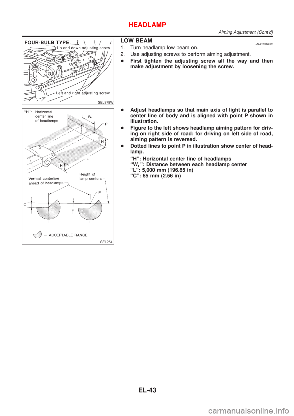
LOW BEAM=NJEL0016S021. Turn headlamp low beam on.
2. Use adjusting screws to perform aiming adjustment.
+First tighten the adjusting screw all the way and then
make adjustment by loosening the screw.
SEL254I
+Adjust headlamps so that main axis of light is parallel to
center line of body and is aligned with point P shown in
illustration.
+Figure to the left shows headlamp aiming pattern for driv-
ing on right side of road; for driving on left side of road,
aiming pattern is reversed.
+Dotted lines to point P in illustration show center of head-
lamp.
ªHº: Horizontal center line of headlamps
ªW
Lº: Distance between each headlamp center
ªLº: 5,000 mm (196.85 in)
ªCº: 65 mm (2.56 in)
HEADLAMP
Aiming Adjustment (Cont'd)
EL-43