change time NISSAN ALMERA N16 2001 Electronic Owner's Manual
[x] Cancel search | Manufacturer: NISSAN, Model Year: 2001, Model line: ALMERA N16, Model: NISSAN ALMERA N16 2001Pages: 2493, PDF Size: 66.97 MB
Page 492 of 2493
SEF010V
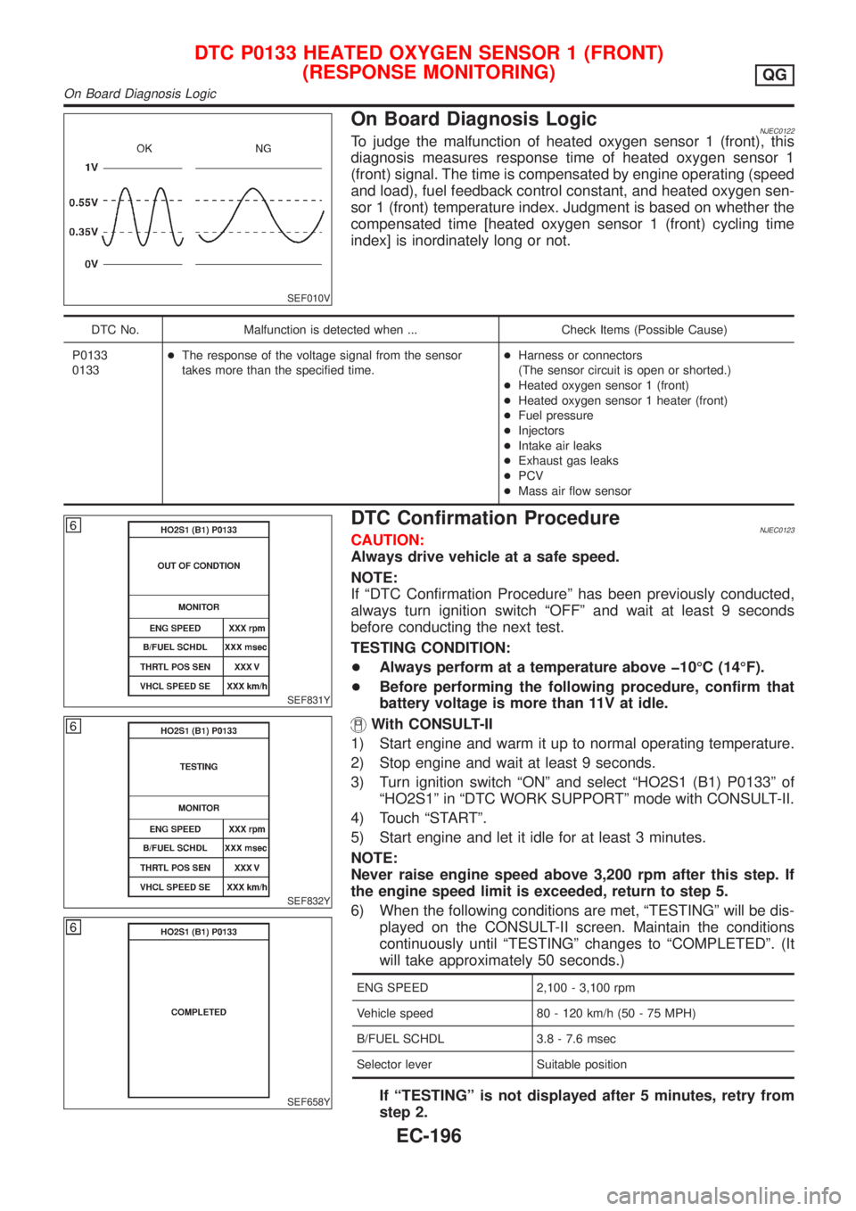
On Board Diagnosis LogicNJEC0122To judge the malfunction of heated oxygen sensor 1 (front), this
diagnosis measures response time of heated oxygen sensor 1
(front) signal. The time is compensated by engine operating (speed
and load), fuel feedback control constant, and heated oxygen sen-
sor 1 (front) temperature index. Judgment is based on whether the
compensated time [heated oxygen sensor 1 (front) cycling time
index] is inordinately long or not.
DTC No. Malfunction is detected when ... Check Items (Possible Cause)
P0133
0133+The response of the voltage signal from the sensor
takes more than the specified time.+Harness or connectors
(The sensor circuit is open or shorted.)
+Heated oxygen sensor 1 (front)
+Heated oxygen sensor 1 heater (front)
+Fuel pressure
+Injectors
+Intake air leaks
+Exhaust gas leaks
+PCV
+Mass air flow sensor
SEF831Y
SEF832Y
SEF658Y
DTC Confirmation ProcedureNJEC0123CAUTION:
Always drive vehicle at a safe speed.
NOTE:
If ªDTC Confirmation Procedureº has been previously conducted,
always turn ignition switch ªOFFº and wait at least 9 seconds
before conducting the next test.
TESTING CONDITION:
+Always perform at a temperature above þ10ÉC (14ÉF).
+Before performing the following procedure, confirm that
battery voltage is more than 11V at idle.
With CONSULT-II
1) Start engine and warm it up to normal operating temperature.
2) Stop engine and wait at least 9 seconds.
3) Turn ignition switch ªONº and select ªHO2S1 (B1) P0133º of
ªHO2S1º in ªDTC WORK SUPPORTº mode with CONSULT-II.
4) Touch ªSTARTº.
5) Start engine and let it idle for at least 3 minutes.
NOTE:
Never raise engine speed above 3,200 rpm after this step. If
the engine speed limit is exceeded, return to step 5.
6) When the following conditions are met, ªTESTINGº will be dis-
played on the CONSULT-II screen. Maintain the conditions
continuously until ªTESTINGº changes to ªCOMPLETEDº. (It
will take approximately 50 seconds.)
ENG SPEED 2,100 - 3,100 rpm
Vehicle speed 80 - 120 km/h (50 - 75 MPH)
B/FUEL SCHDL 3.8 - 7.6 msec
Selector lever Suitable position
If ªTESTINGº is not displayed after 5 minutes, retry from
step 2.
DTC P0133 HEATED OXYGEN SENSOR 1 (FRONT)
(RESPONSE MONITORING)
QG
On Board Diagnosis Logic
EC-196
Page 497 of 2493
8 CHECK HEATED OXYGEN SENSOR 1 (FRONT)
Refer to ªComponent Inspectionº, EC-201.
OK or NG
OK©GO TO 9.
NG©Replace heated oxygen sensor 1 (front).
9 CHECK MASS AIR FLOW SENSOR
Refer to ªComponent Inspectionº, EC-157.
OK or NG
OK©GO TO 10.
NG©Replace mass air flow sensor.
10 CHECK PCV VALVE
Refer to ªPositive Crankcase Ventilationº, EC-37.
OK or NG
OK©GO TO 11.
NG©Repair or replace PCV valve.
11 CHECK INTERMITTENT INCIDENT
Perform ªTROUBLE DIAGNOSIS FOR INTERMITTENT INCIDENTº, EC-144.
©INSPECTION END
SEF646Y
SEF647Y
Component InspectionNJEC0127HEATED OXYGEN SENSOR 1 (FRONT)NJEC0127S02With CONSULT-II
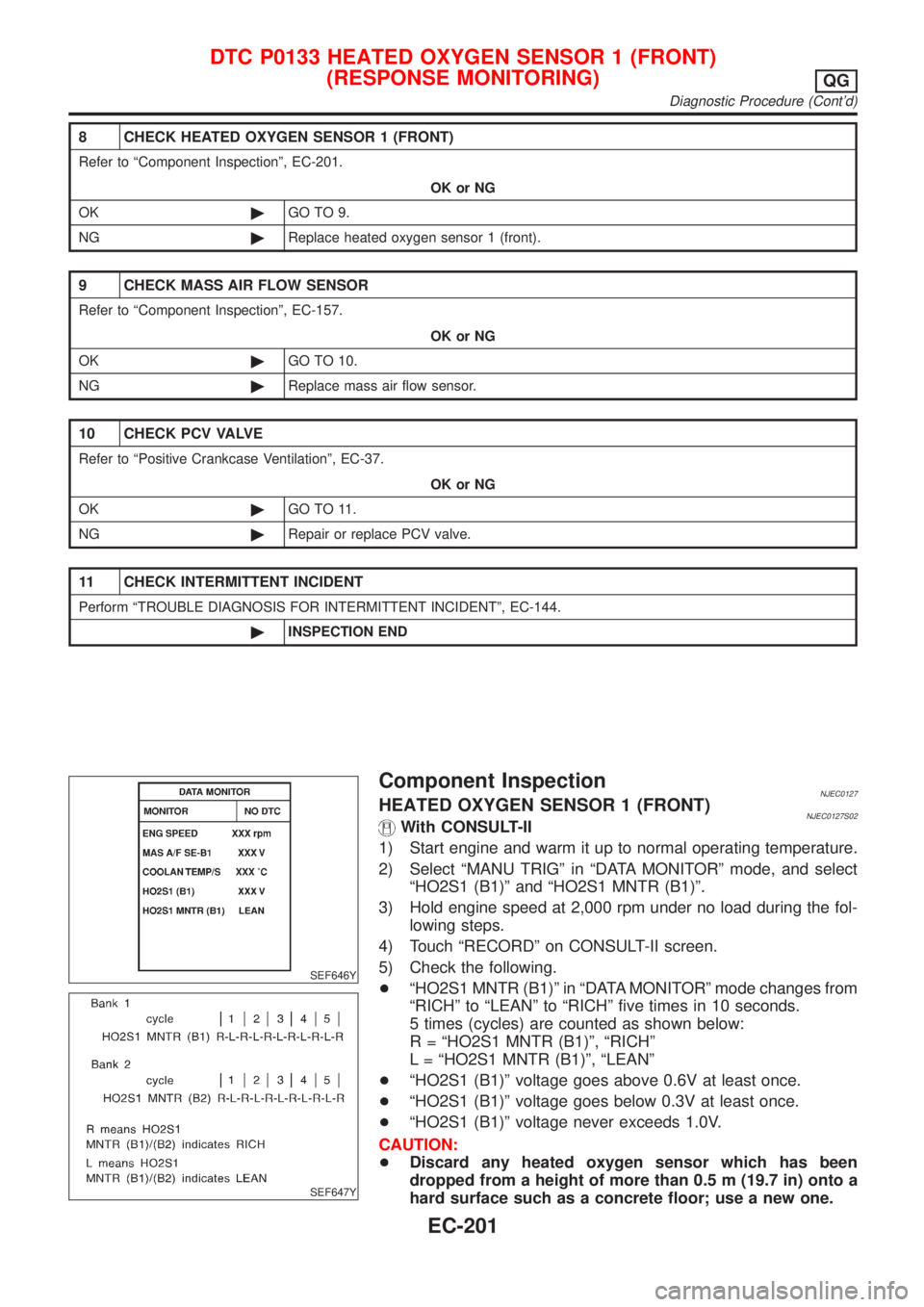
1) Start engine and warm it up to normal operating temperature.
2) Select ªMANU TRIGº in ªDATA MONITORº mode, and select
ªHO2S1 (B1)º and ªHO2S1 MNTR (B1)º.
3) Hold engine speed at 2,000 rpm under no load during the fol-
lowing steps.
4) Touch ªRECORDº on CONSULT-II screen.
5) Check the following.
+ªHO2S1 MNTR (B1)º in ªDATA MONITORº mode changes from
ªRICHº to ªLEANº to ªRICHº five times in 10 seconds.
5 times (cycles) are counted as shown below:
R = ªHO2S1 MNTR (B1)º, ªRICHº
L = ªHO2S1 MNTR (B1)º, ªLEANº
+ªHO2S1 (B1)º voltage goes above 0.6V at least once.
+ªHO2S1 (B1)º voltage goes below 0.3V at least once.
+ªHO2S1 (B1)º voltage never exceeds 1.0V.
CAUTION:
+Discard any heated oxygen sensor which has been
dropped from a height of more than 0.5 m (19.7 in) onto a
hard surface such as a concrete floor; use a new one.
DTC P0133 HEATED OXYGEN SENSOR 1 (FRONT)
(RESPONSE MONITORING)
QG
Diagnostic Procedure (Cont'd)
EC-201
Page 499 of 2493
SEF463R
SEF288D
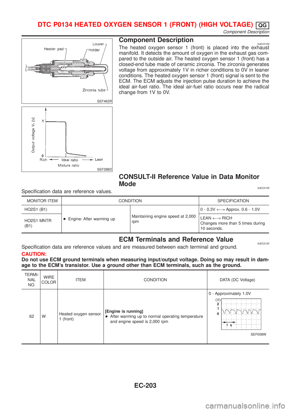
Component DescriptionNJEC0128The heated oxygen sensor 1 (front) is placed into the exhaust
manifold. It detects the amount of oxygen in the exhaust gas com-
pared to the outside air. The heated oxygen sensor 1 (front) has a
closed-end tube made of ceramic zirconia. The zirconia generates
voltage from approximately 1V in richer conditions to 0V in leaner
conditions. The heated oxygen sensor 1 (front) signal is sent to the
ECM. The ECM adjusts the injection pulse duration to achieve the
ideal air-fuel ratio. The ideal air-fuel ratio occurs near the radical
change from 1V to 0V.
CONSULT-II Reference Value in Data Monitor
Mode
NJEC0129Specification data are reference values.
MONITOR ITEM CONDITION SPECIFICATION
HO2S1 (B1)
+Engine: After warming upMaintaining engine speed at 2,000
rpm0 - 0.3V¨Approx. 0.6 - 1.0V
HO2S1 MNTR
(B1)LEAN¨RICH
Changes more than 5 times during
10 seconds.
ECM Terminals and Reference ValueNJEC0130Specification data are reference values and are measured between each terminal and ground.
CAUTION:
Do not use ECM ground terminals when measuring input/output voltage. Doing so may result in dam-
age to the ECM's transistor. Use a ground other than ECM terminals, such as the ground.
TERMI-
NAL
NO.WIRE
COLORITEM CONDITION DATA (DC Voltage)
62 WHeated oxygen sensor
1 (front)[Engine is running]
+After warming up to normal operating temperature
and engine speed is 2,000 rpm0 - Approximately 1.0V
SEF008W
DTC P0134 HEATED OXYGEN SENSOR 1 (FRONT) (HIGH VOLTAGE)QG
Component Description
EC-203
Page 503 of 2493
SEF646Y
SEF647Y
Component InspectionNJEC0135HEATED OXYGEN SENSOR 1 (FRONT)NJEC0135S01With CONSULT-II
1) Start engine and warm it up to normal operating temperature.
2) Select ªMANU TRIGº in ªDATA MONITORº mode, and select
ªHO2S1 (B1)º and ªHO2S1 MNTR (B1)º.
3) Hold engine speed at 2,000 rpm under no load during the fol-
lowing steps.
4) Touch ªRECORDº on CONSULT-II screen.
5) Check the following.
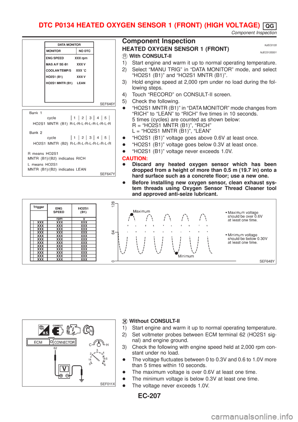
+ªHO2S1 MNTR (B1)º in ªDATA MONITORº mode changes from
ªRICHº to ªLEANº to ªRICHº five times in 10 seconds.
5 times (cycles) are counted as shown below:
R = ªHO2S1 MNTR (B1)º, ªRICHº
L = ªHO2S1 MNTR (B1)º, ªLEANº
+ªHO2S1 (B1)º voltage goes above 0.6V at least once.
+ªHO2S1 (B1)º voltage goes below 0.3V at least once.
+ªHO2S1 (B1)º voltage never exceeds 1.0V.
CAUTION:
+Discard any heated oxygen sensor which has been
dropped from a height of more than 0.5 m (19.7 in) onto a
hard surface such as a concrete floor; use a new one.
+Before installing new oxygen sensor, clean exhaust sys-
tem threads using Oxygen Sensor Thread Cleaner tool
and approved anti-seize lubricant.
SEF648Y
SEF011X
Without CONSULT-II
1) Start engine and warm it up to normal operating temperature.
2) Set voltmeter probes between ECM terminal 62 (HO2S1 sig-
nal) and engine ground.
3) Check the following with engine speed held at 2,000 rpm con-
stant under no load.
+The voltage fluctuates between 0 to 0.3V and 0.6 to 1.0V more
than 5 times within 10 seconds.
+The maximum voltage is over 0.6V at least one time.
+The minimum voltage is below 0.3V at least one time.
+The voltage never exceeds 1.0V.
DTC P0134 HEATED OXYGEN SENSOR 1 (FRONT) (HIGH VOLTAGE)QG
Component Inspection
EC-207
Page 511 of 2493
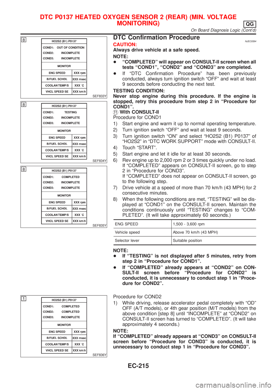
SEF833Y
SEF834Y
SEF835Y
DTC Confirmation ProcedureNJEC0594CAUTION:
Always drive vehicle at a safe speed.
NOTE:
+ªCOMPLETEDº will appear on CONSULT-II screen when all
tests ªCOND1º, ªCOND2º and ªCOND3º are completed.
+If ªDTC Confirmation Procedureº has been previously
conducted, always turn ignition switch ªOFFº and wait at least
9 seconds before conducting the next test.
TESTING CONDITION:
Never stop engine during this procedure. If the engine is
stopped, retry this procedure from step 2 in ªProcedure for
COND1º.
With CONSULT-II
Procedure for COND1
1) Start engine and warm it up to normal operating temperature.
2) Turn ignition switch ªOFFº and wait at least 9 seconds.
3) Turn ignition switch ªONº and select ªHO2S2 (B1) P0137º of
ªHO2S2º in ªDTC WORK SUPPORTº mode with CONSULT-II.
4) Touch ªSTARTº.
5) Start engine and let it idle for at least 30 seconds.
6) Rev engine up to 2,000 rpm 2 or 3 times quickly under no load.
If ªCOMPLETEDº appears on CONSULT-II screen, go to step
2 in ªProcedure for COND3º.
If ªCOMPLETEDº does not appear on CONSULT-II screen, go
to the following step.
7) Drive vehicle at a speed of more than 70 km/h (43 MPH) for 2
consecutive minutes.
8) When the following conditions are met, ªTESTINGº will be dis-
played at ªCOND1º on the CONSULT-II screen. Maintain the
conditions continuously until ªTESTINGº changes to ªCOM-
PLETEDº. (It will take approximately 60 seconds.)
ENG SPEED 1,500 - 3,600 rpm
Vehicle speed Above 70 km/h (43 MPH)
Selector lever Suitable position
NOTE:
+If ªTESTINGº is not displayed after 5 minutes, retry from
step 2 in ªProcedure for COND1º.
+If ªCOMPLETEDº already appears at ªCOND2º on CON-
SULT-II screen before ªProcedure for COND2º is
conducted, it is unnecessary to conduct step 1 in ªProce-
dure for COND2º.
SEF836Y
Procedure for COND2
1) While driving, release accelerator pedal completely with ªODº
OFF (A/T models), or 4th gear position (M/T models) from the
above condition [step 8] until ªINCOMPLETEº at ªCOND2º on
CONSULT-II screen has turned to ªCOMPLETEDº. (It will take
approximately 4 seconds.)
NOTE:
If ªCOMPLETEDº already appears at ªCOND3º on CONSULT-II
screen before ªProcedure for COND3º is conducted, it is
unnecessary to conduct step 1 in ªProcedure for COND3º.
DTC P0137 HEATED OXYGEN SENSOR 2 (REAR) (MIN. VOLTAGE
MONITORING)
QG
On Board Diagnosis Logic (Cont'd)
EC-215
Page 519 of 2493
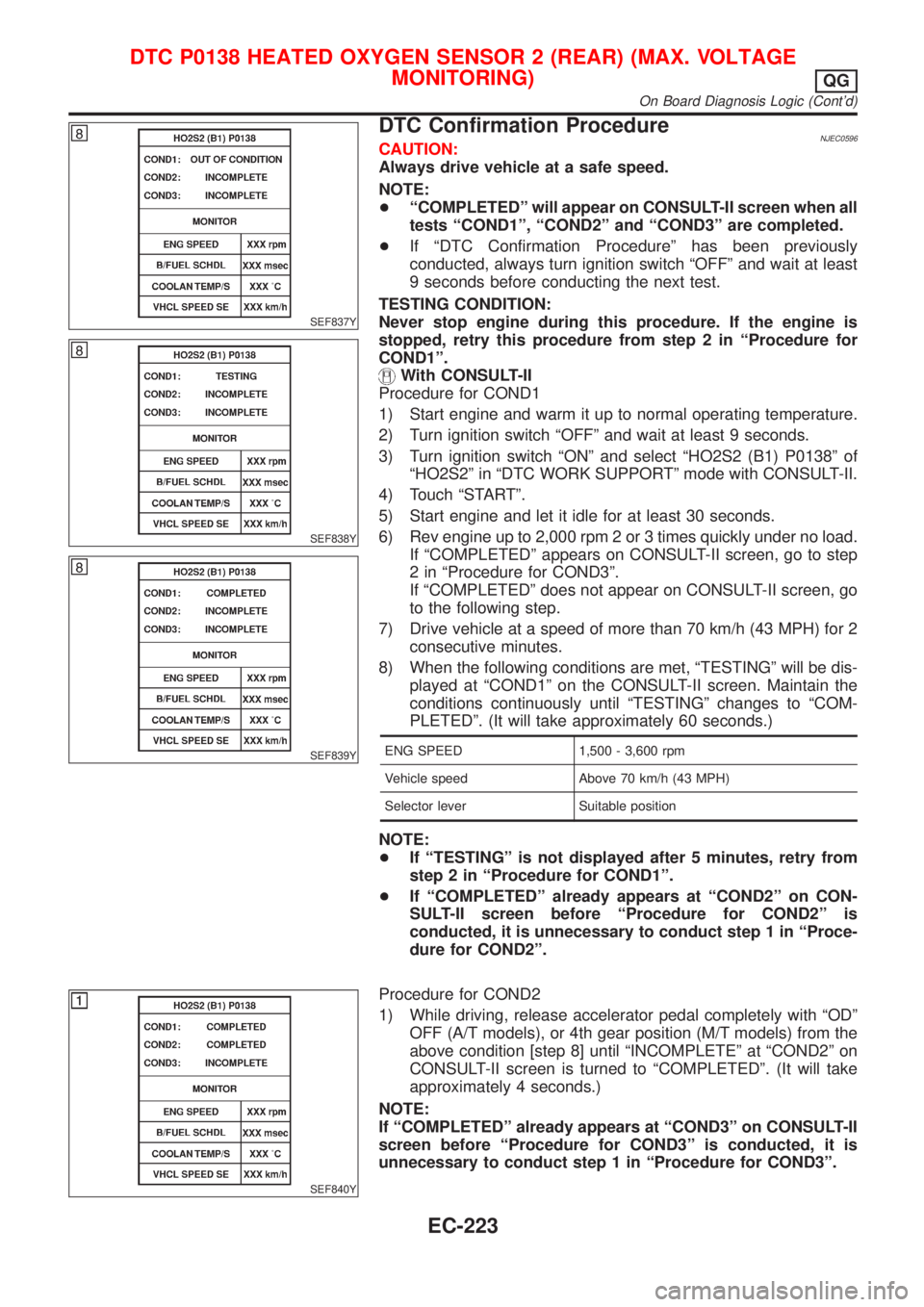
SEF837Y
SEF838Y
SEF839Y
DTC Confirmation ProcedureNJEC0596CAUTION:
Always drive vehicle at a safe speed.
NOTE:
+ªCOMPLETEDº will appear on CONSULT-II screen when all
tests ªCOND1º, ªCOND2º and ªCOND3º are completed.
+If ªDTC Confirmation Procedureº has been previously
conducted, always turn ignition switch ªOFFº and wait at least
9 seconds before conducting the next test.
TESTING CONDITION:
Never stop engine during this procedure. If the engine is
stopped, retry this procedure from step 2 in ªProcedure for
COND1º.
With CONSULT-II
Procedure for COND1
1) Start engine and warm it up to normal operating temperature.
2) Turn ignition switch ªOFFº and wait at least 9 seconds.
3) Turn ignition switch ªONº and select ªHO2S2 (B1) P0138º of
ªHO2S2º in ªDTC WORK SUPPORTº mode with CONSULT-II.
4) Touch ªSTARTº.
5) Start engine and let it idle for at least 30 seconds.
6) Rev engine up to 2,000 rpm 2 or 3 times quickly under no load.
If ªCOMPLETEDº appears on CONSULT-II screen, go to step
2 in ªProcedure for COND3º.
If ªCOMPLETEDº does not appear on CONSULT-II screen, go
to the following step.
7) Drive vehicle at a speed of more than 70 km/h (43 MPH) for 2
consecutive minutes.
8) When the following conditions are met, ªTESTINGº will be dis-
played at ªCOND1º on the CONSULT-II screen. Maintain the
conditions continuously until ªTESTINGº changes to ªCOM-
PLETEDº. (It will take approximately 60 seconds.)
ENG SPEED 1,500 - 3,600 rpm
Vehicle speed Above 70 km/h (43 MPH)
Selector lever Suitable position
NOTE:
+If ªTESTINGº is not displayed after 5 minutes, retry from
step 2 in ªProcedure for COND1º.
+If ªCOMPLETEDº already appears at ªCOND2º on CON-
SULT-II screen before ªProcedure for COND2º is
conducted, it is unnecessary to conduct step 1 in ªProce-
dure for COND2º.
SEF840Y
Procedure for COND2
1) While driving, release accelerator pedal completely with ªODº
OFF (A/T models), or 4th gear position (M/T models) from the
above condition [step 8] until ªINCOMPLETEº at ªCOND2º on
CONSULT-II screen is turned to ªCOMPLETEDº. (It will take
approximately 4 seconds.)
NOTE:
If ªCOMPLETEDº already appears at ªCOND3º on CONSULT-II
screen before ªProcedure for COND3º is conducted, it is
unnecessary to conduct step 1 in ªProcedure for COND3º.
DTC P0138 HEATED OXYGEN SENSOR 2 (REAR) (MAX. VOLTAGE
MONITORING)
QG
On Board Diagnosis Logic (Cont'd)
EC-223
Page 526 of 2493
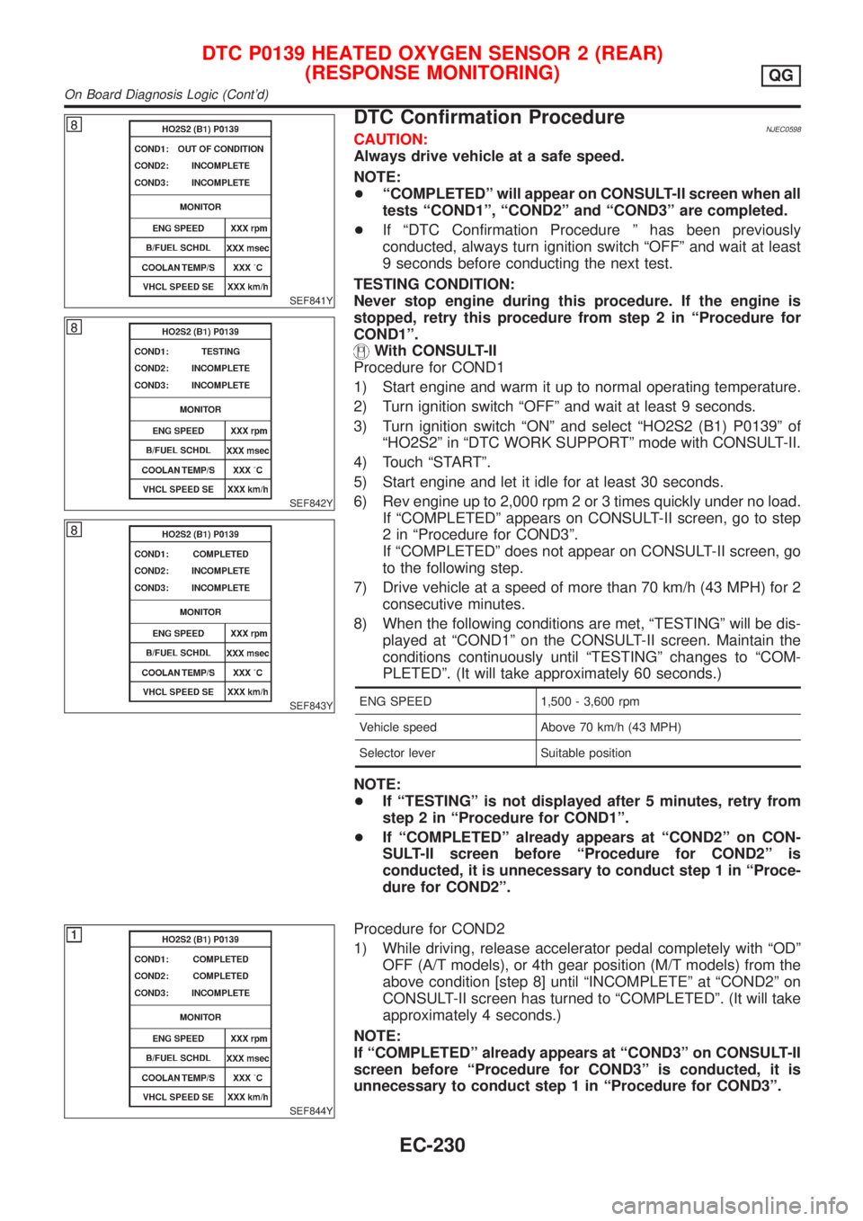
SEF841Y
SEF842Y
SEF843Y
DTC Confirmation ProcedureNJEC0598CAUTION:
Always drive vehicle at a safe speed.
NOTE:
+ªCOMPLETEDº will appear on CONSULT-II screen when all
tests ªCOND1º, ªCOND2º and ªCOND3º are completed.
+If ªDTC Confirmation Procedure º has been previously
conducted, always turn ignition switch ªOFFº and wait at least
9 seconds before conducting the next test.
TESTING CONDITION:
Never stop engine during this procedure. If the engine is
stopped, retry this procedure from step 2 in ªProcedure for
COND1º.
With CONSULT-II
Procedure for COND1
1) Start engine and warm it up to normal operating temperature.
2) Turn ignition switch ªOFFº and wait at least 9 seconds.
3) Turn ignition switch ªONº and select ªHO2S2 (B1) P0139º of
ªHO2S2º in ªDTC WORK SUPPORTº mode with CONSULT-II.
4) Touch ªSTARTº.
5) Start engine and let it idle for at least 30 seconds.
6) Rev engine up to 2,000 rpm 2 or 3 times quickly under no load.
If ªCOMPLETEDº appears on CONSULT-II screen, go to step
2 in ªProcedure for COND3º.
If ªCOMPLETEDº does not appear on CONSULT-II screen, go
to the following step.
7) Drive vehicle at a speed of more than 70 km/h (43 MPH) for 2
consecutive minutes.
8) When the following conditions are met, ªTESTINGº will be dis-
played at ªCOND1º on the CONSULT-II screen. Maintain the
conditions continuously until ªTESTINGº changes to ªCOM-
PLETEDº. (It will take approximately 60 seconds.)
ENG SPEED 1,500 - 3,600 rpm
Vehicle speed Above 70 km/h (43 MPH)
Selector lever Suitable position
NOTE:
+If ªTESTINGº is not displayed after 5 minutes, retry from
step 2 in ªProcedure for COND1º.
+If ªCOMPLETEDº already appears at ªCOND2º on CON-
SULT-II screen before ªProcedure for COND2º is
conducted, it is unnecessary to conduct step 1 in ªProce-
dure for COND2º.
SEF844Y
Procedure for COND2
1) While driving, release accelerator pedal completely with ªODº
OFF (A/T models), or 4th gear position (M/T models) from the
above condition [step 8] until ªINCOMPLETEº at ªCOND2º on
CONSULT-II screen has turned to ªCOMPLETEDº. (It will take
approximately 4 seconds.)
NOTE:
If ªCOMPLETEDº already appears at ªCOND3º on CONSULT-II
screen before ªProcedure for COND3º is conducted, it is
unnecessary to conduct step 1 in ªProcedure for COND3º.
DTC P0139 HEATED OXYGEN SENSOR 2 (REAR)
(RESPONSE MONITORING)
QG
On Board Diagnosis Logic (Cont'd)
EC-230
Page 527 of 2493
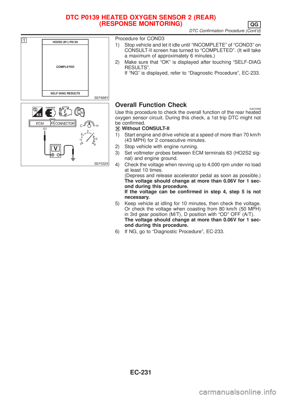
SEF668Y
Procedure for COND3
1) Stop vehicle and let it idle until ªINCOMPLETEº of ªCOND3º on
CONSULT-II screen has turned to ªCOMPLETEDº. (It will take
a maximum of approximately 6 minutes.)
2) Make sure that ªOKº is displayed after touching ªSELF-DIAG
RESULTSº.
If ªNGº is displayed, refer to ªDiagnostic Procedureº, EC-233.
SEF032X
Overall Function CheckNJEC0599Use this procedure to check the overall function of the rear heated
oxygen sensor circuit. During this check, a 1st trip DTC might not
be confirmed.
Without CONSULT-II
1) Start engine and drive vehicle at a speed of more than 70 km/h
(43 MPH) for 2 consecutive minutes.
2) Stop vehicle with engine running.
3) Set voltmeter probes between ECM terminals 63 (HO2S2 sig-
nal) and engine ground.
4) Check the voltage when revving up to 4,000 rpm under no load
at least 10 times.
(Depress and release accelerator pedal as soon as possible.)
The voltage should change at more than 0.06V for 1 sec-
ond during this procedure.
If the voltage can be confirmed in step 4, step 5 is not
necessary.
5) Keep vehicle at idling for 10 minutes, then check the voltage.
Or check the voltage when coasting from 80 km/h (50 MPH)
in 3rd gear position (M/T), D position with ªODº OFF (A/T).
The voltage should change at more than 0.06V for 1 sec-
ond during this procedure.
6) If NG, go to ªDiagnostic Procedureº, EC-233.
DTC P0139 HEATED OXYGEN SENSOR 2 (REAR)
(RESPONSE MONITORING)
QG
DTC Confirmation Procedure (Cont'd)
EC-231
Page 582 of 2493
SEF552W
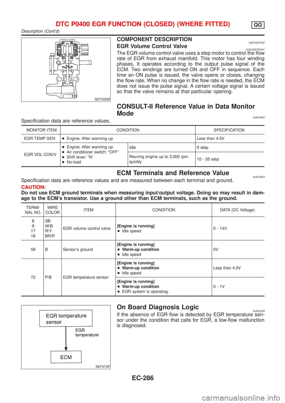
COMPONENT DESCRIPTIONNJEC0227S02EGR Volume Control ValveNJEC0227S0201The EGR volume control valve uses a step motor to control the flow
rate of EGR from exhaust manifold. This motor has four winding
phases. It operates according to the output pulse signal of the
ECM. Two windings are turned ON and OFF in sequence. Each
time an ON pulse is issued, the valve opens or closes, changing
the flow rate. When no change in the flow rate is needed, the ECM
does not issue the pulse signal. A certain voltage signal is issued
so that the valve remains at that particular opening.
CONSULT-II Reference Value in Data Monitor
Mode
NJEC0502Specification data are reference values.
MONITOR ITEM CONDITION SPECIFICATION
EGR TEMP SEN+Engine: After warming up Less than 4.5V
EGR VOL CON/V+Engine: After warming up
+Air conditioner switch: ªOFFº
+Shift lever: ªNº
+No-loadIdle 0 step
Revving engine up to 3,000 rpm
quickly10 - 55 step
ECM Terminals and Reference ValueNJEC0503Specification data are reference values and are measured between each terminal and ground.
CAUTION:
Do not use ECM ground terminals when measuring input/output voltage. Doing so may result in dam-
age to the ECM's transistor. Use a ground other than ECM terminals, such as the ground.
TERMI-
NAL NO.WIRE
COLORITEM CONDITION DATA (DC Voltage)
8
9
17
18SB
W/B
R/Y
BR/REGR volume control valve[Engine is running]
+Idle speed0 - 14V
58 B Sensor's ground[Engine is running]
+Warm-up condition
+Idle speed0V
72 P/B EGR temperature sensor[Engine is running]
+Warm-up condition
+Idle speedLess than 4.5V
[Engine is running]
+Warm-up condition
+EGR system is operating.0-1V
SEF073P
On Board Diagnosis LogicNJEC0228If the absence of EGR flow is detected by EGR temperature sen-
sor under the condition that calls for EGR, a low-flow malfunction
is diagnosed.
DTC P0400 EGR FUNCTION (CLOSED) (WHERE FITTED)QG
Description (Cont'd)
EC-286
Page 590 of 2493
SEF552W
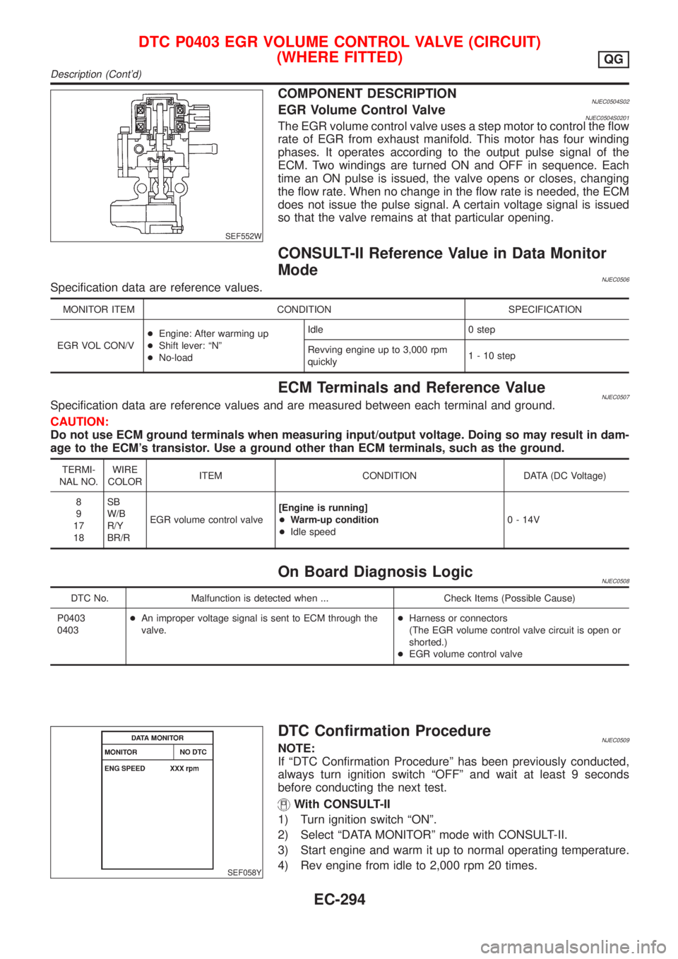
COMPONENT DESCRIPTIONNJEC0504S02EGR Volume Control ValveNJEC0504S0201The EGR volume control valve uses a step motor to control the flow
rate of EGR from exhaust manifold. This motor has four winding
phases. It operates according to the output pulse signal of the
ECM. Two windings are turned ON and OFF in sequence. Each
time an ON pulse is issued, the valve opens or closes, changing
the flow rate. When no change in the flow rate is needed, the ECM
does not issue the pulse signal. A certain voltage signal is issued
so that the valve remains at that particular opening.
CONSULT-II Reference Value in Data Monitor
Mode
NJEC0506Specification data are reference values.
MONITOR ITEM CONDITION SPECIFICATION
EGR VOL CON/V+Engine: After warming up
+Shift lever: ªNº
+No-loadIdle 0 step
Revving engine up to 3,000 rpm
quickly1 - 10 step
ECM Terminals and Reference ValueNJEC0507Specification data are reference values and are measured between each terminal and ground.
CAUTION:
Do not use ECM ground terminals when measuring input/output voltage. Doing so may result in dam-
age to the ECM's transistor. Use a ground other than ECM terminals, such as the ground.
TERMI-
NAL NO.WIRE
COLORITEM CONDITION DATA (DC Voltage)
8
9
17
18SB
W/B
R/Y
BR/REGR volume control valve[Engine is running]
+Warm-up condition
+Idle speed0 - 14V
On Board Diagnosis LogicNJEC0508
DTC No. Malfunction is detected when ... Check Items (Possible Cause)
P0403
0403+An improper voltage signal is sent to ECM through the
valve.+Harness or connectors
(The EGR volume control valve circuit is open or
shorted.)
+EGR volume control valve
SEF058Y
DTC Confirmation ProcedureNJEC0509NOTE:
If ªDTC Confirmation Procedureº has been previously conducted,
always turn ignition switch ªOFFº and wait at least 9 seconds
before conducting the next test.
With CONSULT-II
1) Turn ignition switch ªONº.
2) Select ªDATA MONITORº mode with CONSULT-II.
3) Start engine and warm it up to normal operating temperature.
4) Rev engine from idle to 2,000 rpm 20 times.
DTC P0403 EGR VOLUME CONTROL VALVE (CIRCUIT)
(WHERE FITTED)
QG
Description (Cont'd)
EC-294