change time NISSAN ALMERA N16 2001 Electronic Workshop Manual
[x] Cancel search | Manufacturer: NISSAN, Model Year: 2001, Model line: ALMERA N16, Model: NISSAN ALMERA N16 2001Pages: 2493, PDF Size: 66.97 MB
Page 1389 of 2493
Diagnostic trouble code Malfunction is detected when ... Check items (Possible cause)
: A/T 1ST GR FNCTN
A/T cannot be shifted to the 1st gear
position even if electrical circuit is good.+Shift solenoid valve A
+Shift solenoid valve B
+Each clutch
+Hydraulic control circuit
: P0731
SAT014K
SAT971J
SAT021J
DIAGNOSTIC TROUBLE CODE (DTC) CONFIRMATION
PROCEDURE
NJAT0279S03CAUTION:
+Always drive vehicle at a safe speed.
+Be careful not to rev engine into the red zone on the
tachometer.
NOTE:
If ªDIAGNOSTIC TROUBLE CODE CONFIRMATION PROCE-
DUREº has been previously conducted, always turn ignition
switch ªOFFº and wait at least 5 seconds before conducting
the next test.
TESTING CONDITION:
Always drive vehicle on a level road to improve the accuracy
of test.
After the repair, perform the following procedure to confirm the
malfunction is eliminated.
With CONSULT-II
1) Start engine and select ªDATA MONITORº mode for ªA/Tº with
CONSULT-II.
2) Make sure that output voltage of A/T fluid temperature sensor
is within the range below.
FLUID TEMP SEN: 0.4 - 1.5V
If out of range, drive the vehicle to decrease the voltage (warm
up the fluid) or stop engine to increase the voltage (cool down
the fluid).
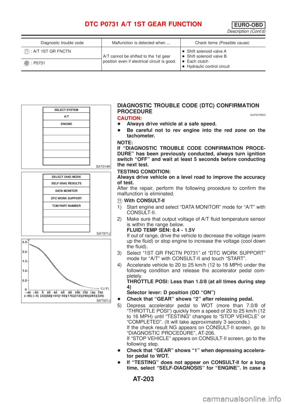
3) Select ª1ST GR FNCTN P0731º of ªDTC WORK SUPPORTº
mode for ªA/Tº with CONSULT-II and touch ªSTARTº.
4) Accelerate vehicle to 20 to 25 km/h (12 to 16 MPH) under the
following condition and release the accelerator pedal com-
pletely.
THROTTLE POSI: Less than 1.0/8 (at all times during step
4)
Selector lever: D position (OD ªONº)
+Check that ªGEARº shows ª2º after releasing pedal.
5) Depress accelerator pedal to WOT (more than 7.0/8 of
ªTHROTTLE POSIº) quickly from a speed of 20 to 25 km/h (12
to 16 MPH) until ªTESTINGº changes to ªSTOP VEHICLEº or
ªCOMPLETEDº. (It will take approximately 3 seconds.)
If the check result NG appears on CONSULT-II screen, go to
ªDIAGNOSTIC PROCEDUREº, AT-206.
If ªSTOP VEHICLEº appears on CONSULT-II screen, go to the
following step.
+Check that ªGEARº shows ª1º when depressing accelera-
tor pedal to WOT.
+If ªTESTINGº does not appear on CONSULT-II for a long
time, select ªSELF-DIAGNOSISº for ªENGINEº. In case a
DTC P0731 A/T 1ST GEAR FUNCTIONEURO-OBD
Description (Cont'd)
AT-203
Page 1396 of 2493
SAT014K
SAT971J
SAT021J
DIAGNOSTIC TROUBLE CODE (DTC) CONFIRMATION
PROCEDURE
NJAT0283S03CAUTION:
+Always drive vehicle at a safe speed.
+Be careful not to rev engine into the red zone on the
tachometer.
NOTE:
If ªDIAGNOSTIC TROUBLE CODE CONFIRMATION PROCE-
DUREº has been previously conducted, always turn ignition
switch ªOFFº and wait at least 5 seconds before conducting
the next test.
TESTING CONDITION:
Always drive vehicle on a level road to improve the accuracy
of test.
After the repair, perform the following procedure to confirm the
malfunction is eliminated.
With CONSULT-II
1) Start engine and select ªDATA MONITORº mode for ªA/Tº with
CONSULT-II.
2) Make sure that output voltage of A/T fluid temperature sensor
is within the range below.
FLUID TEMP SEN: 0.4 - 1.5V
If out of range, drive the vehicle to decrease the voltage (warm
up the fluid) or stop engine to increase the voltage (cool down
the fluid).
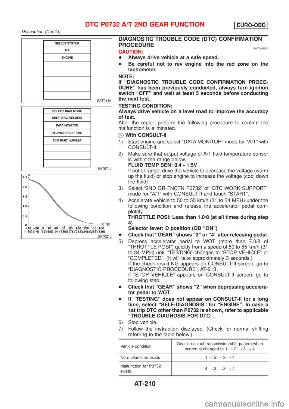
3) Select ª2ND GR FNCTN P0732º of ªDTC WORK SUPPORTº
mode for ªA/Tº with CONSULT-II and touch ªSTARTº.
4) Accelerate vehicle to 50 to 55 km/h (31 to 34 MPH) under the
following condition and release the accelerator pedal com-
pletely.
THROTTLE POSI: Less than 1.0/8 (at all times during step
4)
Selector lever: D position (OD ªONº)
+Check that ªGEARº shows ª3º or ª4º after releasing pedal.
5) Depress accelerator pedal to WOT (more than 7.0/8 of
ªTHROTTLE POSIº) quickly from a speed of 50 to 55 km/h (31
to 34 MPH) until ªTESTINGº changes to ªSTOP VEHICLEº or
ªCOMPLETEDº. (It will take approximately 3 seconds.)
If the check result NG appears on CONSULT-II screen, go to
ªDIAGNOSTIC PROCEDUREº, AT-213.
If ªSTOP VEHICLEº appears on CONSULT-II screen, go to
following step.
+Check that ªGEARº shows ª2º when depressing accelera-
tor pedal to WOT.
+If ªTESTINGº does not appear on CONSULT-II for a long
time, select ªSELF-DIAGNOSISº for ªENGINEº. In case a
1st trip DTC other than P0732 is shown, refer to applicable
ªTROUBLE DIAGNOSIS FOR DTCº.
6) Stop vehicle.
7) Follow the instruction displayed. (Check for normal shifting
referring to the table below.)
Vehicle conditionGear on actual transmission shift pattern when
screen is changed to 1®2®3®4
No malfunction exists 1®2®3®4
Malfunction for P0732
exists.4®3®3®4
DTC P0732 A/T 2ND GEAR FUNCTIONEURO-OBD
Description (Cont'd)
AT-210
Page 1402 of 2493
SAT014K
SAT971J
SAT021J
DIAGNOSTIC TROUBLE CODE (DTC) CONFIRMATION
PROCEDURE
NJAT0287S03CAUTION:
+Always drive vehicle at a safe speed.
+Be careful not to rev engine into the red zone on the
tachometer.
NOTE:
If ªDIAGNOSTIC TROUBLE CODE CONFIRMATION PROCE-
DUREº has been previously conducted, always turn ignition
switch ªOFFº and wait at least 5 seconds before conducting
the next test.
TESTING CONDITION:
Always drive vehicle on a level road to improve the accuracy
of test.
After the repair, perform the following procedure to confirm the
malfunction is eliminated.
With CONSULT-II
1) Start engine and select ªDATA MONITORº mode for ªA/Tº with
CONSULT-II.
2) Make sure that output voltage of A/T fluid temperature sensor
is within the range below.
FLUID TEMP SEN: 0.4 - 1.5V
If out of range, drive the vehicle to decrease the voltage (warm
up the fluid) or stop engine to increase the voltage (cool down
the fluid).
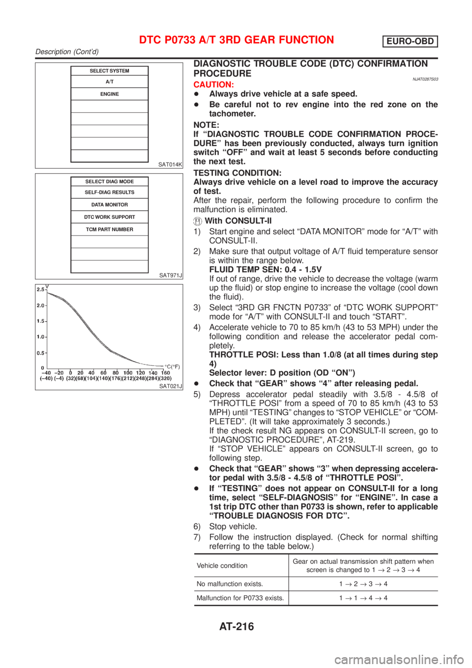
3) Select ª3RD GR FNCTN P0733º of ªDTC WORK SUPPORTº
mode for ªA/Tº with CONSULT-II and touch ªSTARTº.
4) Accelerate vehicle to 70 to 85 km/h (43 to 53 MPH) under the
following condition and release the accelerator pedal com-
pletely.
THROTTLE POSI: Less than 1.0/8 (at all times during step
4)
Selector lever: D position (OD ªONº)
+Check that ªGEARº shows ª4º after releasing pedal.
5) Depress accelerator pedal steadily with 3.5/8 - 4.5/8 of
ªTHROTTLE POSIº from a speed of 70 to 85 km/h (43 to 53
MPH) until ªTESTINGº changes to ªSTOP VEHICLEº or ªCOM-
PLETEDº. (It will take approximately 3 seconds.)
If the check result NG appears on CONSULT-II screen, go to
ªDIAGNOSTIC PROCEDUREº, AT-219.
If ªSTOP VEHICLEº appears on CONSULT-II screen, go to
following step.
+Check that ªGEARº shows ª3º when depressing accelera-
tor pedal with 3.5/8 - 4.5/8 of ªTHROTTLE POSIº.
+If ªTESTINGº does not appear on CONSULT-II for a long
time, select ªSELF-DIAGNOSISº for ªENGINEº. In case a
1st trip DTC other than P0733 is shown, refer to applicable
ªTROUBLE DIAGNOSIS FOR DTCº.
6) Stop vehicle.
7) Follow the instruction displayed. (Check for normal shifting
referring to the table below.)
Vehicle conditionGear on actual transmission shift pattern when
screen is changed to 1®2®3®4
No malfunction exists. 1®2®3®4
Malfunction for P0733 exists. 1®1®4®4
DTC P0733 A/T 3RD GEAR FUNCTIONEURO-OBD
Description (Cont'd)
AT-216
Page 1718 of 2493
SBR002A
SBR365AA
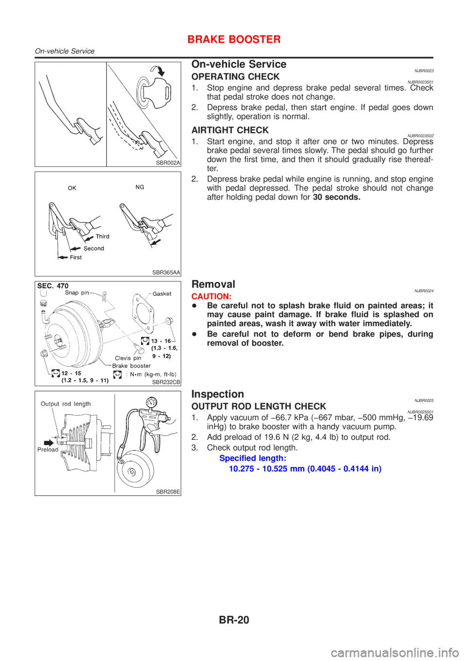
On-vehicle ServiceNJBR0023OPERATING CHECKNJBR0023S011. Stop engine and depress brake pedal several times. Check
that pedal stroke does not change.
2. Depress brake pedal, then start engine. If pedal goes down
slightly, operation is normal.
AIRTIGHT CHECKNJBR0023S021. Start engine, and stop it after one or two minutes. Depress
brake pedal several times slowly. The pedal should go further
down the first time, and then it should gradually rise thereaf-
ter.
2. Depress brake pedal while engine is running, and stop engine
with pedal depressed. The pedal stroke should not change
after holding pedal down for30 seconds.
SBR232CB
RemovalNJBR0024CAUTION:
+Be careful not to splash brake fluid on painted areas; it
may cause paint damage. If brake fluid is splashed on
painted areas, wash it away with water immediately.
+Be careful not to deform or bend brake pipes, during
removal of booster.
SBR208E
InspectionNJBR0025OUTPUT ROD LENGTH CHECKNJBR0025S011. Apply vacuum of þ66.7 kPa (þ667 mbar, þ500 mmHg, þ19.69
inHg) to brake booster with a handy vacuum pump.
2. Add preload of 19.6 N (2 kg, 4.4 lb) to output rod.
3. Check output rod length.
Specified length:
10.275 - 10.525 mm (0.4045 - 0.4144 in)
BRAKE BOOSTER
On-vehicle Service
BR-20
Page 1862 of 2493
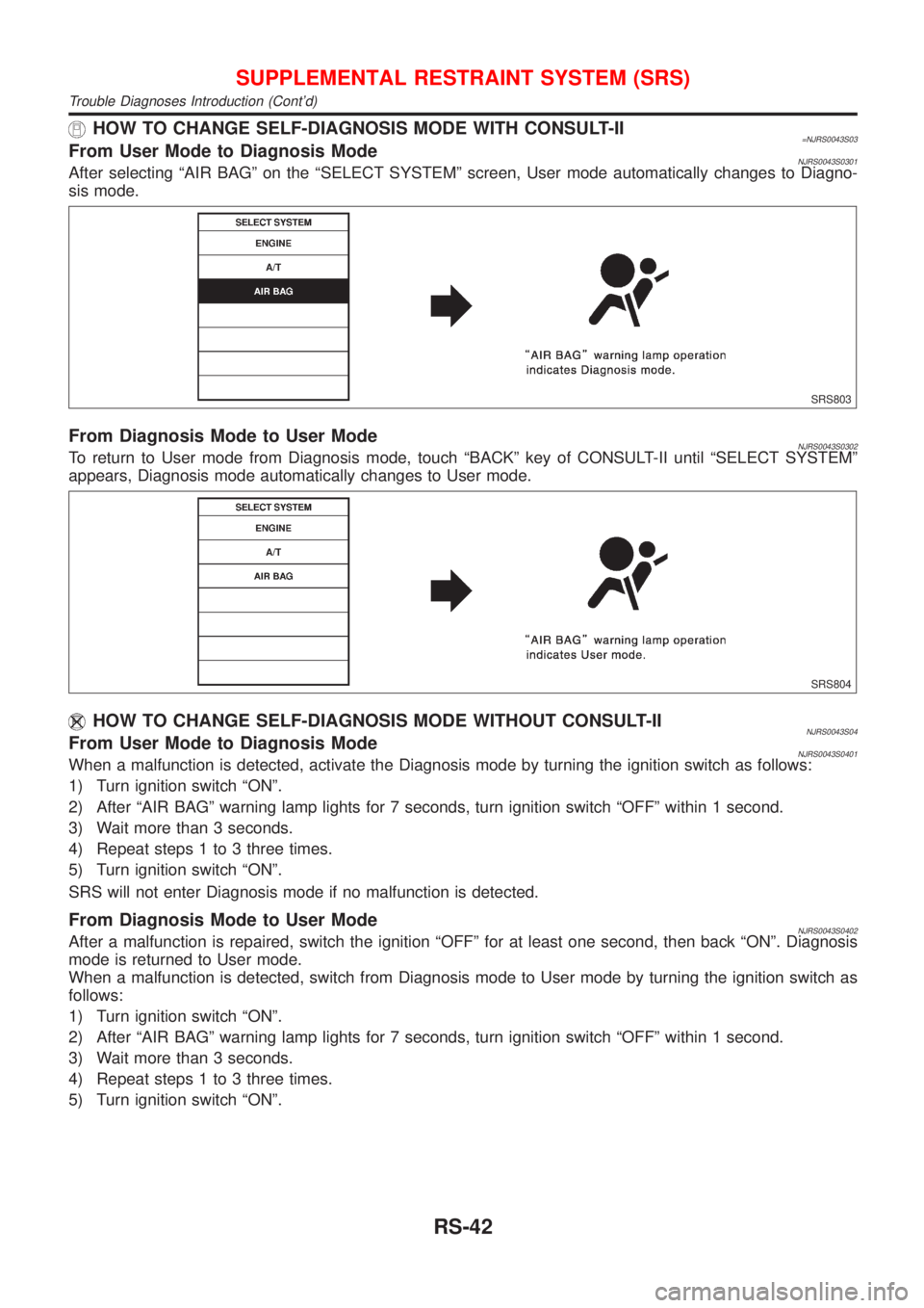
HOW TO CHANGE SELF-DIAGNOSIS MODE WITH CONSULT-II=NJRS0043S03From User Mode to Diagnosis ModeNJRS0043S0301After selecting ªAIR BAGº on the ªSELECT SYSTEMº screen, User mode automatically changes to Diagno-
sis mode.
SRS803
From Diagnosis Mode to User ModeNJRS0043S0302To return to User mode from Diagnosis mode, touch ªBACKº key of CONSULT-II until ªSELECT SYSTEMº
appears, Diagnosis mode automatically changes to User mode.
SRS804
HOW TO CHANGE SELF-DIAGNOSIS MODE WITHOUT CONSULT-IINJRS0043S04From User Mode to Diagnosis ModeNJRS0043S0401When a malfunction is detected, activate the Diagnosis mode by turning the ignition switch as follows:
1) Turn ignition switch ªONº.
2) After ªAIR BAGº warning lamp lights for 7 seconds, turn ignition switch ªOFFº within 1 second.
3) Wait more than 3 seconds.
4) Repeat steps 1 to 3 three times.
5) Turn ignition switch ªONº.
SRS will not enter Diagnosis mode if no malfunction is detected.
From Diagnosis Mode to User ModeNJRS0043S0402After a malfunction is repaired, switch the ignition ªOFFº for at least one second, then back ªONº. Diagnosis
mode is returned to User mode.
When a malfunction is detected, switch from Diagnosis mode to User mode by turning the ignition switch as
follows:
1) Turn ignition switch ªONº.
2) After ªAIR BAGº warning lamp lights for 7 seconds, turn ignition switch ªOFFº within 1 second.
3) Wait more than 3 seconds.
4) Repeat steps 1 to 3 three times.
5) Turn ignition switch ªONº.
SUPPLEMENTAL RESTRAINT SYSTEM (SRS)
Trouble Diagnoses Introduction (Cont'd)
RS-42
Page 1979 of 2493
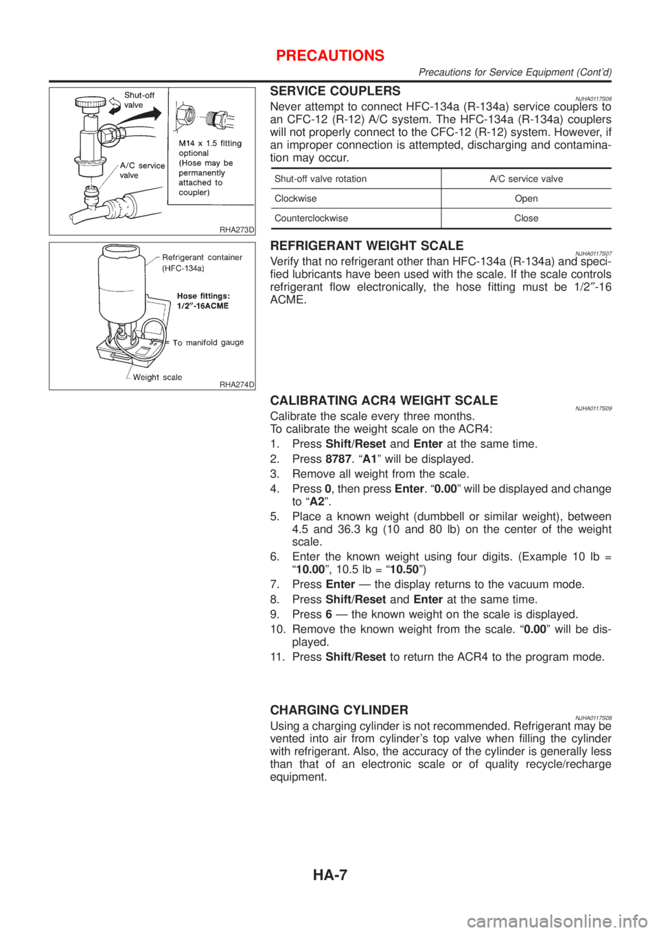
RHA273D
SERVICE COUPLERSNJHA0117S06Never attempt to connect HFC-134a (R-134a) service couplers to
an CFC-12 (R-12) A/C system. The HFC-134a (R-134a) couplers
will not properly connect to the CFC-12 (R-12) system. However, if
an improper connection is attempted, discharging and contamina-
tion may occur.
Shut-off valve rotation A/C service valve
Clockwise Open
Counterclockwise Close
RHA274D
REFRIGERANT WEIGHT SCALENJHA0117S07Verify that no refrigerant other than HFC-134a (R-134a) and speci-
fied lubricants have been used with the scale. If the scale controls
refrigerant flow electronically, the hose fitting must be 1/2²-16
ACME.
CALIBRATING ACR4 WEIGHT SCALENJHA0117S09Calibrate the scale every three months.
To calibrate the weight scale on the ACR4:
1. PressShift/ResetandEnterat the same time.
2. Press8787.ªA1º will be displayed.
3. Remove all weight from the scale.
4. Press0, then pressEnter.ª0.00º will be displayed and change
to ªA2º.
5. Place a known weight (dumbbell or similar weight), between
4.5 and 36.3 kg (10 and 80 lb) on the center of the weight
scale.
6. Enter the known weight using four digits. (Example 10 lb =
ª10.00º, 10.5 lb = ª10.50º)
7. PressEnterÐ the display returns to the vacuum mode.
8. PressShift/ResetandEnterat the same time.
9. Press6Ð the known weight on the scale is displayed.
10. Remove the known weight from the scale. ª0.00º will be dis-
played.
11. PressShift/Resetto return the ACR4 to the program mode.
CHARGING CYLINDERNJHA0117S08Using a charging cylinder is not recommended. Refrigerant may be
vented into air from cylinder's top valve when filling the cylinder
with refrigerant. Also, the accuracy of the cylinder is generally less
than that of an electronic scale or of quality recycle/recharge
equipment.
PRECAUTIONS
Precautions for Service Equipment (Cont'd)
HA-7
Page 2051 of 2493
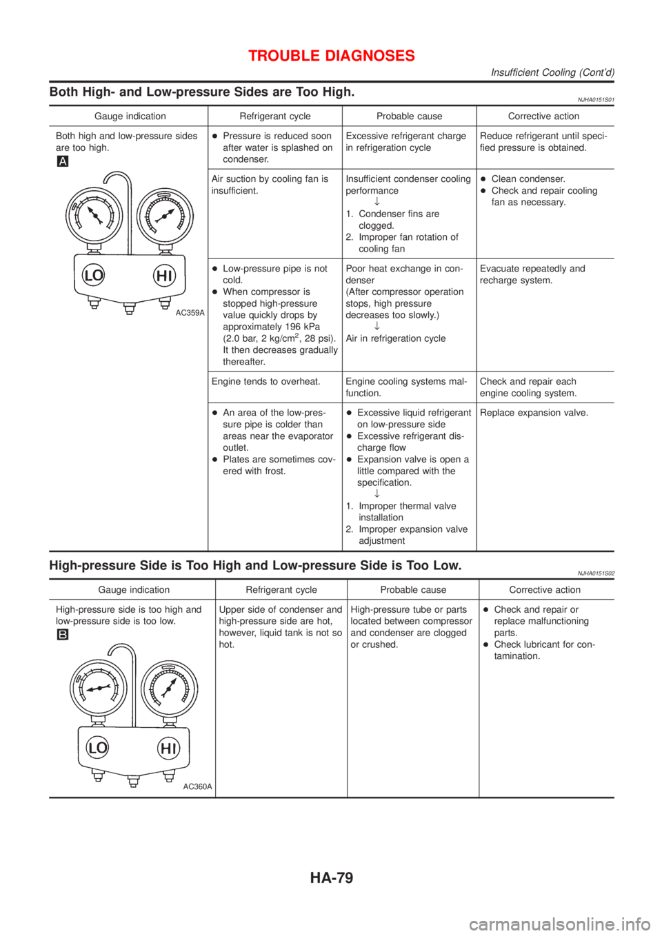
Both High- and Low-pressure Sides are Too High.NJHA0151S01
Gauge indication Refrigerant cycle Probable cause Corrective action
Both high and low-pressure sides
are too high.
AC359A
+Pressure is reduced soon
after water is splashed on
condenser.Excessive refrigerant charge
in refrigeration cycleReduce refrigerant until speci-
fied pressure is obtained.
Air suction by cooling fan is
insufficient.Insufficient condenser cooling
performance
¯
1. Condenser fins are
clogged.
2. Improper fan rotation of
cooling fan+Clean condenser.
+Check and repair cooling
fan as necessary.
+Low-pressure pipe is not
cold.
+When compressor is
stopped high-pressure
value quickly drops by
approximately 196 kPa
(2.0 bar, 2 kg/cm
2, 28 psi).
It then decreases gradually
thereafter.Poor heat exchange in con-
denser
(After compressor operation
stops, high pressure
decreases too slowly.)
¯
Air in refrigeration cycleEvacuate repeatedly and
recharge system.
Engine tends to overheat. Engine cooling systems mal-
function.Check and repair each
engine cooling system.
+An area of the low-pres-
sure pipe is colder than
areas near the evaporator
outlet.
+Plates are sometimes cov-
ered with frost.+Excessive liquid refrigerant
on low-pressure side
+Excessive refrigerant dis-
charge flow
+Expansion valve is open a
little compared with the
specification.
¯
1. Improper thermal valve
installation
2. Improper expansion valve
adjustmentReplace expansion valve.
High-pressure Side is Too High and Low-pressure Side is Too Low.NJHA0151S02
Gauge indication Refrigerant cycle Probable cause Corrective action
High-pressure side is too high and
low-pressure side is too low.
AC360A
Upper side of condenser and
high-pressure side are hot,
however, liquid tank is not so
hot.High-pressure tube or parts
located between compressor
and condenser are clogged
or crushed.+Check and repair or
replace malfunctioning
parts.
+Check lubricant for con-
tamination.
TROUBLE DIAGNOSES
Insufficient Cooling (Cont'd)
HA-79
Page 2201 of 2493
Component Parts and Harness Connector
Location
NJEL0441For details, refer to ªELECTRICAL UNIT LOCATIONº (EL-319) and
ªHARNESS LAYOUTº (EL-324).
System DescriptionNJEL0442UNIFIED CONTROL METERNJEL0442S01+Speedometer, odo/trip meter, tachometer, fuel gauge and water temperature gauge are controlled totally
by control unit built-in combination meter.
+Digital meter is adopted for odo/trip meter.*
*The record of the odo meter is kept even if the battery cable is disconnected. The record of the trip meter
is erased when the battery cable is disconnected.
+Odo/trip meter segment can be checked in diagnosis mode.
+Meter/gauge can be checked in diagnosis mode.
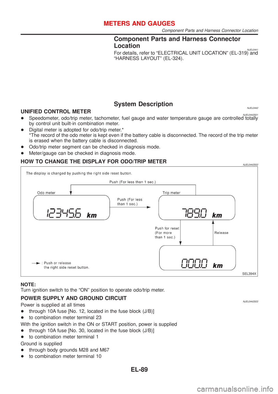
HOW TO CHANGE THE DISPLAY FOR ODO/TRIP METERNJEL0442S02
SEL394X
NOTE:
Turn ignition switch to the ªONº position to operate odo/trip meter.
POWER SUPPLY AND GROUND CIRCUITNJEL0442S03Power is supplied at all times
+through 10A fuse [No. 12, located in the fuse block (J/B)]
+to combination meter terminal 23
With the ignition switch in the ON or START position, power is supplied
+through 10A fuse [No. 30, located in the fuse block (J/B)]
+to combination meter terminal 1
Ground is supplied
+through body grounds M28 and M67
+to combination meter terminal 10
METERS AND GAUGES
Component Parts and Harness Connector Location
EL-89
Page 2261 of 2493
System Description=NJEL0497Refer to Owner's Manual for audio system operating instructions.
Power is supplied at all times
+through 15A fuse (No. 32, located in the fusible link and fuse block)
+to audio unit terminal 9
+to CD auto changer terminal 32.
With the ignition switch in the ACC or ON position, power is supplied
+through 10A fuse [No. 1, located in the fuse block (J/B)]
+to audio unit terminal 3,
+to CD auto changer terminal 36 and
Ground is supplied through the case of the audio unit.
Audio signals are supplied
+through audio unit terminals 7, 10, 11, 12, 13, 14, 15, 16
+to terminals 1 and 2 of front door speaker LH and RH,
+to terminals 1 and 2 of rear door speaker LH and RH and
+to terminals 1 and 2 of pillar tweeter LH and RH (with 6 speakers)
When the navigation system is triggered,
power is supplied
+through navi control unit terminal 46
+to speaker relay terminal 2
Ground is supplied
+through navi control unit terminal 44
+to speaker relay terminal 1
With power and ground supplied, the relay is energized, and then audio signal is interrupted to front door
speaker LH (LHD models) or RH (RHD models), and pillar tweeter LH (LHD models) or RH (RHD models)
For detailed, refer to ªNAVIGATION SYSTEMº.
NATS AUDIO LINKNJEL0497S01DescriptionNJEL0497S0101The link with the NATS IMMU implies that the audio unit can basically only be operated if connected to the
matching NATS IMMU to which the audio unit was initially fitted on the production line.
Since radio operation is impossible after the link with the NATS is disrupted theft of the audio unit is basically
useless since special equipment is required to reset the audio unit.
Initialization process for audio units that are linked to the NATS IMMU
New audio units will be delivered to the factories in the ªNEWº state, i.e. ready to be linked with the vehicle's
NATS. When the audio unit in ªNEWº state is first switched on at the factory, it will start up communication
with the vehicle's immobiliser control unit (IMMU) and send a code (the ªaudio unit Codeº) to the IMMU. The
IMMU will then store this code, which is unique to each audio unit, in its (permanent) memory.
Upon receipt of the code by the IMMU, the NATS will confirm correct receipt of the audio unit code to the audio
unit. Hereafter, the audio unit will operate as normal.
During the initialisation process, ªNEWº is displayed on the audio unit display. Normally though, communica-
tion between audio unit and IMMU takes such a short time (300 ms) that the audio unit seems to switch on
directly without showing ªNEWº on its display.
Normal operation
Each time the audio unit is switched on afterwards, the audio unit code will be verified between the audio unit
and the NATS before the audio unit becomes operational. During the code verification process, ªWAITº is
shown on the audio unit display. Again, the communication takes such a short time (300 ms) that the audio
unit seems to switch on directly without showing ªWAITº on its display.
When the radio is locked
In case of a audio unit being linked with the vehicle's NATS (immobilizer system), disconnection of the link
between the audio unit and the IMMU will cause the audio unit to switch into the lock (ªSECUREº) mode in
which the audio unit is fully inoperative. Hence, repair of the audio unit is basically impossible, unless the audio
unit is reset to the ªNEWº state for which special decoding equipment is required.
Clarion has provided their authorized service representatives with so called ªdecoder boxesº which can bring
the audio unit back to the ªNEWº state, enabling the audio unit to be switched on after which repair can be
AUDIO
System Description
EL-149
Page 2343 of 2493
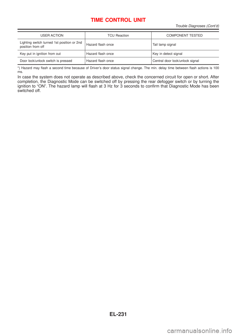
USER ACTION TCU Reaction COMPONENT TESTED
Lighting switch turned 1st position or 2nd
position from offHazard flash once Tail lamp signal
Key put in ignition from out Hazard flash once Key in detect signal
Door lock/unlock switch is pressed Hazard flash once Central door lock/unlock signal
*) Hazard may flash a second time because of Driver's door status signal change. The min. delay time between flash actions is 100
ms.
In case the system does not operate as described above, check the concerned circuit for open or short. After
completion, the Diagnostic Mode can be switched off by pressing the rear defogger switch or by turning the
ignition to ªONº. The hazard lamp will flash at 3 Hz for 3 seconds to confirm that Diagnostic Mode has been
switched off.
TIME CONTROL UNIT
Trouble Diagnoses (Cont'd)
EL-231