door lock NISSAN ALMERA N16 2001 Electronic Repair Manual
[x] Cancel search | Manufacturer: NISSAN, Model Year: 2001, Model line: ALMERA N16, Model: NISSAN ALMERA N16 2001Pages: 2493, PDF Size: 66.97 MB
Page 58 of 2493
NJMA0036
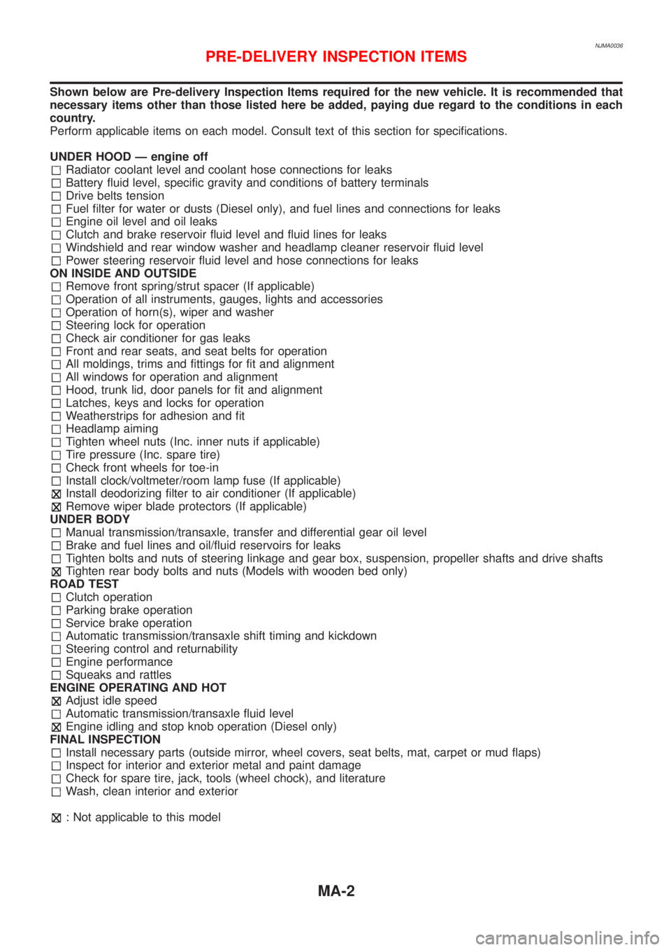
Shown below are Pre-delivery Inspection Items required for the new vehicle. It is recommended that
necessary items other than those listed here be added, paying due regard to the conditions in each
country.
Perform applicable items on each model. Consult text of this section for specifications.
UNDER HOOD Ð engine off
Radiator coolant level and coolant hose connections for leaks
Battery fluid level, specific gravity and conditions of battery terminals
Drive belts tension
Fuel filter for water or dusts (Diesel only), and fuel lines and connections for leaks
Engine oil level and oil leaks
Clutch and brake reservoir fluid level and fluid lines for leaks
Windshield and rear window washer and headlamp cleaner reservoir fluid level
Power steering reservoir fluid level and hose connections for leaks
ON INSIDE AND OUTSIDE
Remove front spring/strut spacer (If applicable)
Operation of all instruments, gauges, lights and accessories
Operation of horn(s), wiper and washer
Steering lock for operation
Check air conditioner for gas leaks
Front and rear seats, and seat belts for operation
All moldings, trims and fittings for fit and alignment
All windows for operation and alignment
Hood, trunk lid, door panels for fit and alignment
Latches, keys and locks for operation
Weatherstrips for adhesion and fit
Headlamp aiming
Tighten wheel nuts (Inc. inner nuts if applicable)
Tire pressure (Inc. spare tire)
Check front wheels for toe-in
Install clock/voltmeter/room lamp fuse (If applicable)
Install deodorizing filter to air conditioner (If applicable)
Remove wiper blade protectors (If applicable)
UNDER BODY
Manual transmission/transaxle, transfer and differential gear oil level
Brake and fuel lines and oil/fluid reservoirs for leaks
Tighten bolts and nuts of steering linkage and gear box, suspension, propeller shafts and drive shafts
Tighten rear body bolts and nuts (Models with wooden bed only)
ROAD TEST
Clutch operation
Parking brake operation
Service brake operation
Automatic transmission/transaxle shift timing and kickdown
Steering control and returnability
Engine performance
Squeaks and rattles
ENGINE OPERATING AND HOT
Adjust idle speed
Automatic transmission/transaxle fluid level
Engine idling and stop knob operation (Diesel only)
FINAL INSPECTION
Install necessary parts (outside mirror, wheel covers, seat belts, mat, carpet or mud flaps)
Inspect for interior and exterior metal and paint damage
Check for spare tire, jack, tools (wheel chock), and literature
Wash, clean interior and exterior
: Not applicable to this model
PRE-DELIVERY INSPECTION ITEMS
MA-2
Page 59 of 2493
NJMA0004
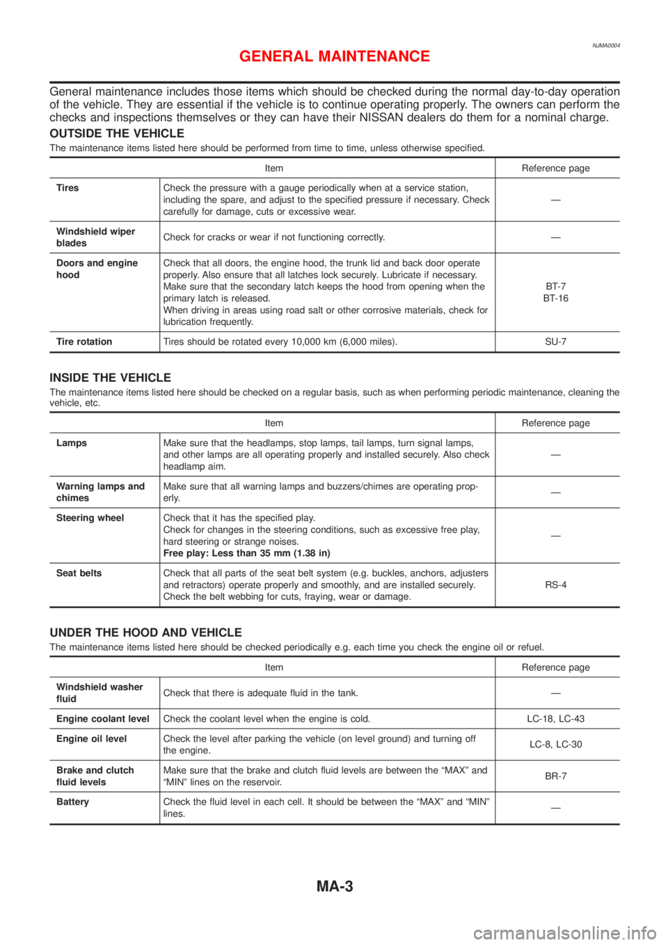
General maintenance includes those items which should be checked during the normal day-to-day operation
of the vehicle. They are essential if the vehicle is to continue operating properly. The owners can perform the
checks and inspections themselves or they can have their NISSAN dealers do them for a nominal charge.
OUTSIDE THE VEHICLE
The maintenance items listed here should be performed from time to time, unless otherwise specified.
Item Reference page
TiresCheck the pressure with a gauge periodically when at a service station,
including the spare, and adjust to the specified pressure if necessary. Check
carefully for damage, cuts or excessive wear.Ð
Windshield wiper
bladesCheck for cracks or wear if not functioning correctly. Ð
Doors and engine
hoodCheck that all doors, the engine hood, the trunk lid and back door operate
properly. Also ensure that all latches lock securely. Lubricate if necessary.
Make sure that the secondary latch keeps the hood from opening when the
primary latch is released.
When driving in areas using road salt or other corrosive materials, check for
lubrication frequently.BT-7
BT-16
Tire rotationTires should be rotated every 10,000 km (6,000 miles). SU-7
INSIDE THE VEHICLE
The maintenance items listed here should be checked on a regular basis, such as when performing periodic maintenance, cleaning the
vehicle, etc.
Item Reference page
LampsMake sure that the headlamps, stop lamps, tail lamps, turn signal lamps,
and other lamps are all operating properly and installed securely. Also check
headlamp aim.Ð
Warning lamps and
chimesMake sure that all warning lamps and buzzers/chimes are operating prop-
erly.Ð
Steering wheelCheck that it has the specified play.
Check for changes in the steering conditions, such as excessive free play,
hard steering or strange noises.
Free play: Less than 35 mm (1.38 in)Ð
Seat beltsCheck that all parts of the seat belt system (e.g. buckles, anchors, adjusters
and retractors) operate properly and smoothly, and are installed securely.
Check the belt webbing for cuts, fraying, wear or damage.RS-4
UNDER THE HOOD AND VEHICLE
The maintenance items listed here should be checked periodically e.g. each time you check the engine oil or refuel.
Item Reference page
Windshield washer
fluidCheck that there is adequate fluid in the tank. Ð
Engine coolant levelCheck the coolant level when the engine is cold. LC-18, LC-43
Engine oil levelCheck the level after parking the vehicle (on level ground) and turning off
the engine.LC-8, LC-30
Brake and clutch
fluid levelsMake sure that the brake and clutch fluid levels are between the ªMAXº and
ªMINº lines on the reservoir.BR-7
BatteryCheck the fluid level in each cell. It should be between the ªMAXº and ªMINº
lines.Ð
GENERAL MAINTENANCE
MA-3
Page 1855 of 2493
Disposal of Air Bag Module and Seat Belt Pre-
tensioner
NJRS0022+Before disposing of air bag module and seat belt pre-tensioner,
or vehicles equipped with such systems, deploy the systems.
If such systems have already been deployed due to an
accident, dispose of them as indicated in ªDISPOSING OF AIR
BAG MODULE AND SEAT BELT PRE-TENSIONERº (RS-40).
+When deploying the air bag module and seat belt pre-
tensioner, always use the Special Service Tool; Deployment
tool KV99106400.
+When deploying the air bag module and seat belt pre-
tensioner, stand at least 5 m (16 ft) away from the deployment
component.
+When deploying air bag module and seat belt pre-tensioner, a
fairly loud noise is made, followed by smoke being released.
The smoke is not poisonous, however, be careful not to inhale
smoke since it irritates the throat and can cause choking.
+Always activate one air bag module at a time.
+Due to heat, leave air bag module unattended for more than
30 minutes after deployment. Also leave seat belt pre-ten-
sioner unattended for move than 10 minutes after deployment.
+Be sure to wear gloves when handling a deployed air bag
module and seat belt pre-tensioner.
+Never apply water to the deployed air bag module and seat
belt pre-tensioner.
+Wash your hands clean after finishing work.
+Place the vehicle outdoors with an open space of at least 6 m
(20 ft) on all sides when deploying air bag module and seat belt
pre-tensioner while mounted in vehicle.
+Use a voltmeter to make sure the vehicle battery is fully
charged.
+Do not dispose of the air bag module and seat belt pre-ten-
sioner un-deployed.
SRS005-B
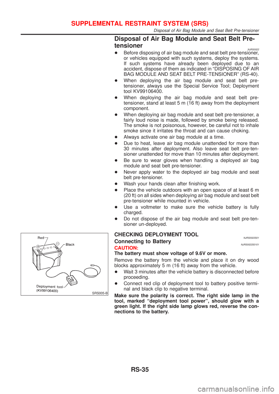
CHECKING DEPLOYMENT TOOLNJRS0022S01Connecting to BatteryNJRS0022S0101CAUTION:
The battery must show voltage of 9.6V or more.
Remove the battery from the vehicle and place it on dry wood
blocks approximately 5 m (16 ft) away from the vehicle.
+Wait 3 minutes after the vehicle battery is disconnected before
proceeding.
+Connect red clip of deployment tool to battery positive termi-
nal and black clip to negative terminal.
Make sure the polarity is correct. The right side lamp in the
tool, marked ªdeployment tool powerº, should glow with a
green light. If the right side lamp glows red, reverse the con-
nections to the battery.
SUPPLEMENTAL RESTRAINT SYSTEM (SRS)
Disposal of Air Bag Module and Seat Belt Pre-tensioner
RS-35
Page 1895 of 2493
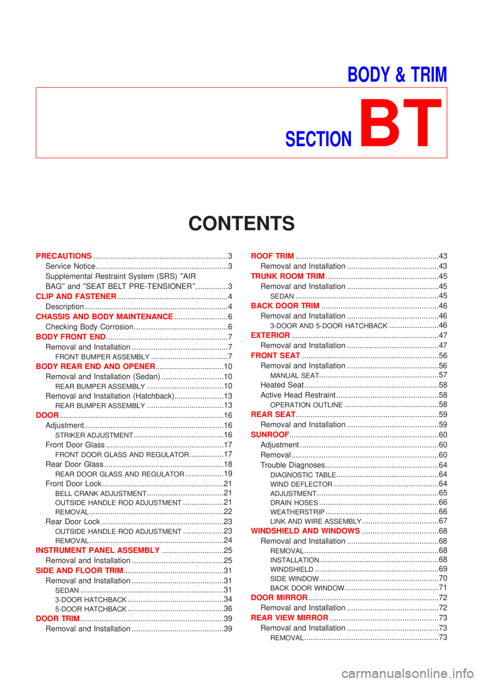
BODY & TRIM
SECTION
BT
CONTENTS
PRECAUTIONS...............................................................3
Service Notice..............................................................3
Supplemental Restraint System (SRS)²AIR
BAG²and²SEAT BELT PRE-TENSIONER²...............3
CLIP AND FASTENER....................................................4
Description ...................................................................4
CHASSIS AND BODY MAINTENANCE.........................6
Checking Body Corrosion ............................................6
BODY FRONT END.........................................................7
Removal and Installation .............................................7
FRONT BUMPER ASSEMBLY....................................7
BODY REAR END AND OPENER................................10
Removal and Installation (Sedan) .............................10
REAR BUMPER ASSEMBLY....................................10
Removal and Installation (Hatchback).......................13
REAR BUMPER ASSEMBLY....................................13
DOOR.............................................................................16
Adjustment .................................................................16
STRIKER ADJUSTMENT..........................................16
Front Door Glass .......................................................17
FRONT DOOR GLASS AND REGULATOR................17
Rear Door Glass ........................................................18
REAR DOOR GLASS AND REGULATOR..................19
Front Door Lock .........................................................21
BELL CRANK ADJUSTMENT....................................21
OUTSIDE HANDLE ROD ADJUSTMENT...................21
REMOVAL...............................................................22
Rear Door Lock .........................................................23
OUTSIDE HANDLE ROD ADJUSTMENT...................23
REMOVAL...............................................................24
INSTRUMENT PANEL ASSEMBLY.............................25
Removal and Installation ...........................................25
SIDE AND FLOOR TRIM...............................................31
Removal and Installation ...........................................31
SEDAN...................................................................31
3-DOOR HATCHBACK.............................................34
5-DOOR HATCHBACK.............................................36
DOOR TRIM...................................................................39
Removal and Installation ...........................................39ROOF TRIM...................................................................43
Removal and Installation ...........................................43
TRUNK ROOM TRIM.....................................................45
Removal and Installation ...........................................45
SEDAN...................................................................45
BACK DOOR TRIM.......................................................46
Removal and Installation ...........................................46
3-DOOR AND 5-DOOR HATCHBACK.......................46
EXTERIOR.....................................................................47
Removal and Installation ...........................................47
FRONT SEAT................................................................56
Removal and Installation ...........................................56
MANUAL SEAT........................................................57
Heated Seat ...............................................................58
Active Head Restraint ................................................58
OPERATION OUTLINE............................................58
REAR SEAT...................................................................59
Removal and Installation ...........................................59
SUNROOF......................................................................60
Adjustment .................................................................60
Removal .....................................................................60
Trouble Diagnoses.....................................................64
DIAGNOSTIC TABLE................................................64
WIND DEFLECTOR.................................................64
ADJUSTMENT.........................................................65
DRAIN HOSES........................................................66
WEATHERSTRIP.....................................................66
LINK AND WIRE ASSEMBLY....................................67
WINDSHIELD AND WINDOWS....................................68
Removal and Installation ...........................................68
REMOVAL...............................................................68
INSTALLATION........................................................68
WINDSHIELD..........................................................69
SIDE WINDOW........................................................70
BACK DOOR WINDOW............................................71
DOOR MIRROR.............................................................72
Removal and Installation ...........................................72
REAR VIEW MIRROR...................................................73
Removal and Installation ...........................................73
REMOVAL...............................................................73
Page 1907 of 2493
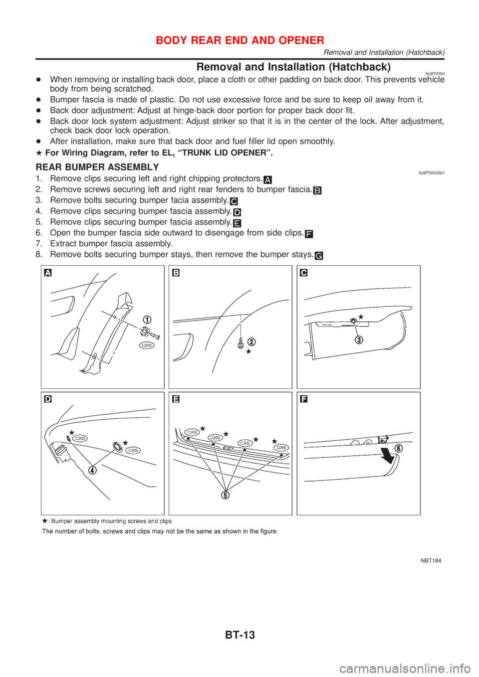
Removal and Installation (Hatchback)NJBT0034+When removing or installing back door, place a cloth or other padding on back door. This prevents vehicle
body from being scratched.
+Bumper fascia is made of plastic. Do not use excessive force and be sure to keep oil away from it.
+Back door adjustment: Adjust at hinge-back door portion for proper back door fit.
+Back door lock system adjustment: Adjust striker so that it is in the center of the lock. After adjustment,
check back door lock operation.
+After installation, make sure that back door and fuel filler lid open smoothly.
HFor Wiring Diagram, refer to EL, ªTRUNK LID OPENERº.
REAR BUMPER ASSEMBLYNJBT0034S011. Remove clips securing left and right chipping protectors.
2. Remove screws securing left and right rear fenders to bumper fascia.
3. Remove bolts securing bumper facia assembly.
4. Remove clips securing bumper fascia assembly.
5. Remove clips securing bumper fascia assembly.
6. Open the bumper fascia side outward to disengage from side clips.
7. Extract bumper fascia assembly.
8. Remove bolts securing bumper stays, then remove the bumper stays.
NBT184
BODY REAR END AND OPENER
Removal and Installation (Hatchback)
BT-13
Page 1910 of 2493
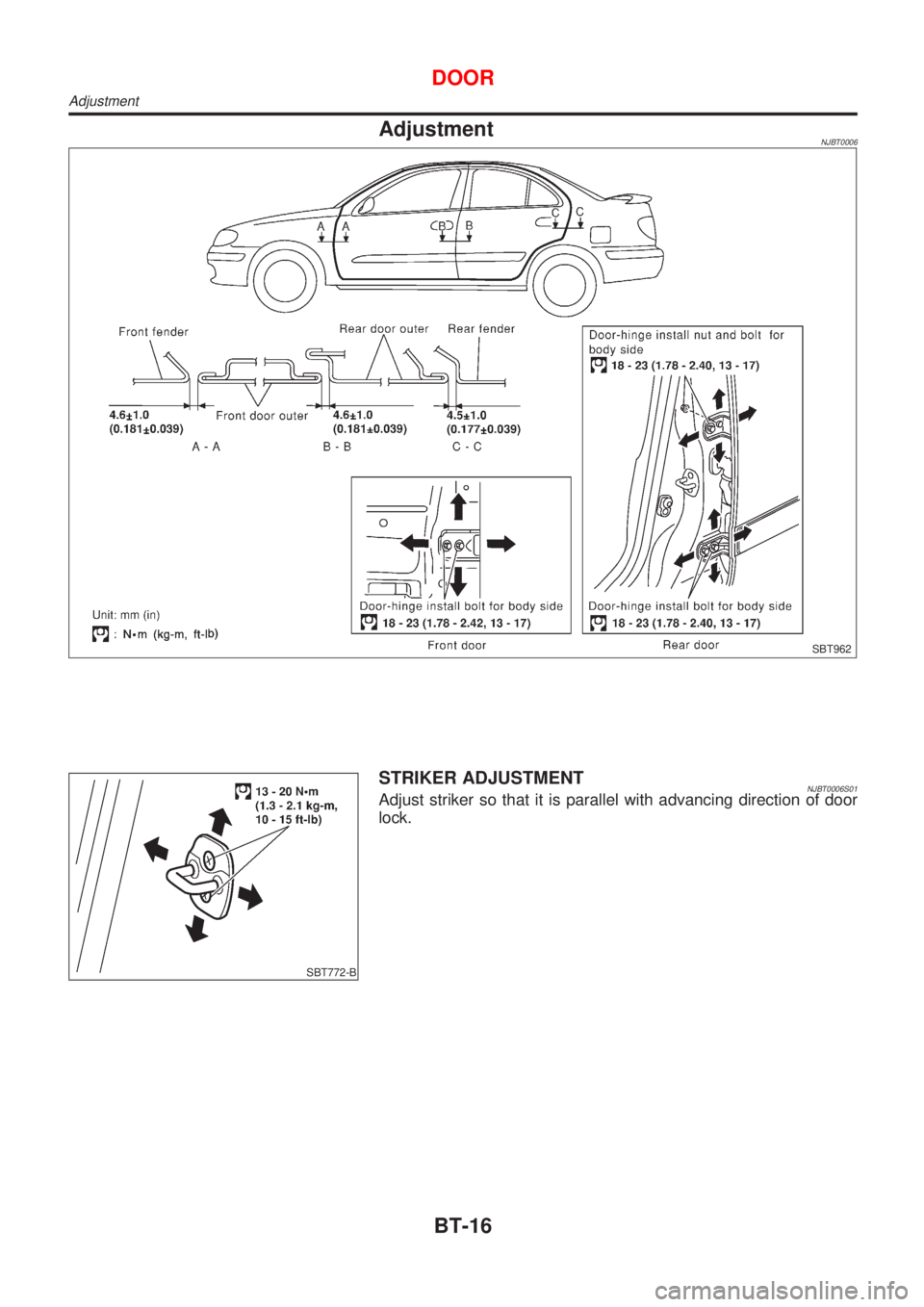
AdjustmentNJBT0006
SBT962
SBT772-B
STRIKER ADJUSTMENTNJBT0006S01Adjust striker so that it is parallel with advancing direction of door
lock.
DOOR
Adjustment
BT-16
Page 1915 of 2493
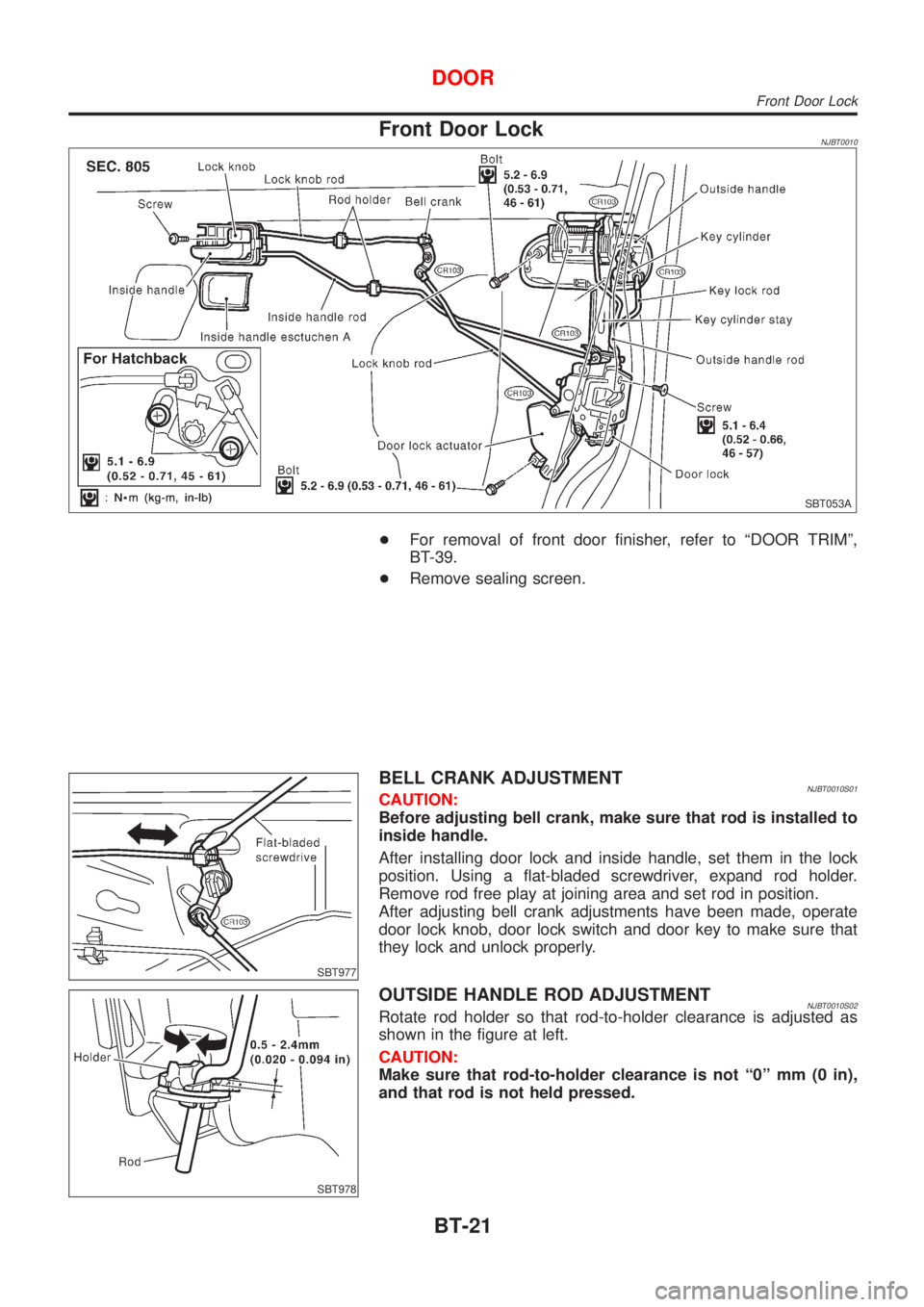
Front Door LockNJBT0010
SBT053A
+For removal of front door finisher, refer to ªDOOR TRIMº,
BT-39.
+Remove sealing screen.
SBT977
BELL CRANK ADJUSTMENTNJBT0010S01CAUTION:
Before adjusting bell crank, make sure that rod is installed to
inside handle.
After installing door lock and inside handle, set them in the lock
position. Using a flat-bladed screwdriver, expand rod holder.
Remove rod free play at joining area and set rod in position.
After adjusting bell crank adjustments have been made, operate
door lock knob, door lock switch and door key to make sure that
they lock and unlock properly.
SBT978
OUTSIDE HANDLE ROD ADJUSTMENTNJBT0010S02Rotate rod holder so that rod-to-holder clearance is adjusted as
shown in the figure at left.
CAUTION:
Make sure that rod-to-holder clearance is not ª0º mm (0 in),
and that rod is not held pressed.
DOOR
Front Door Lock
BT-21
Page 1916 of 2493
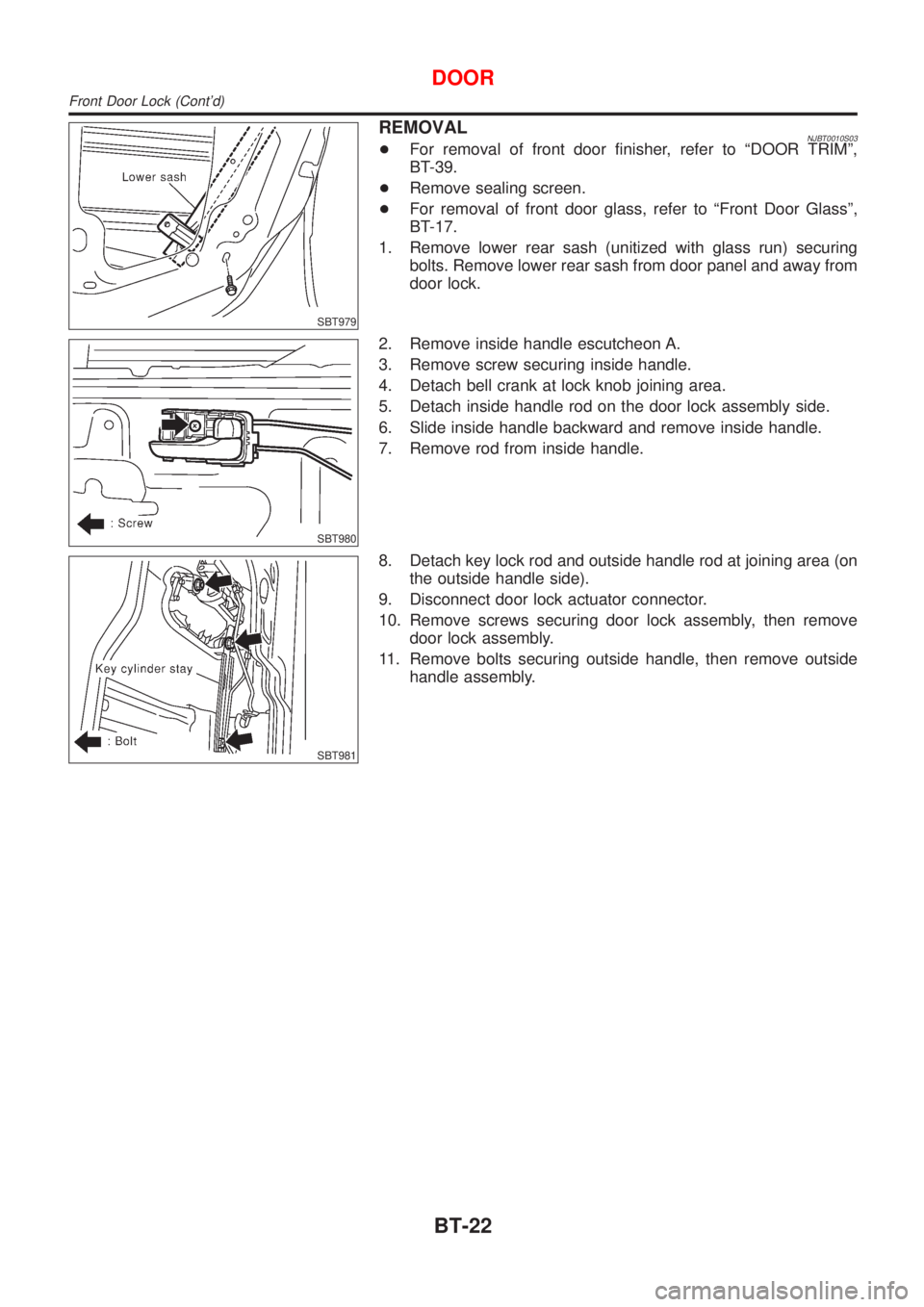
SBT979
REMOVALNJBT0010S03+For removal of front door finisher, refer to ªDOOR TRIMº,
BT-39.
+Remove sealing screen.
+For removal of front door glass, refer to ªFront Door Glassº,
BT-17.
1. Remove lower rear sash (unitized with glass run) securing
bolts. Remove lower rear sash from door panel and away from
door lock.
SBT980
2. Remove inside handle escutcheon A.
3. Remove screw securing inside handle.
4. Detach bell crank at lock knob joining area.
5. Detach inside handle rod on the door lock assembly side.
6. Slide inside handle backward and remove inside handle.
7. Remove rod from inside handle.
SBT981
8. Detach key lock rod and outside handle rod at joining area (on
the outside handle side).
9. Disconnect door lock actuator connector.
10. Remove screws securing door lock assembly, then remove
door lock assembly.
11. Remove bolts securing outside handle, then remove outside
handle assembly.
DOOR
Front Door Lock (Cont'd)
BT-22
Page 1917 of 2493
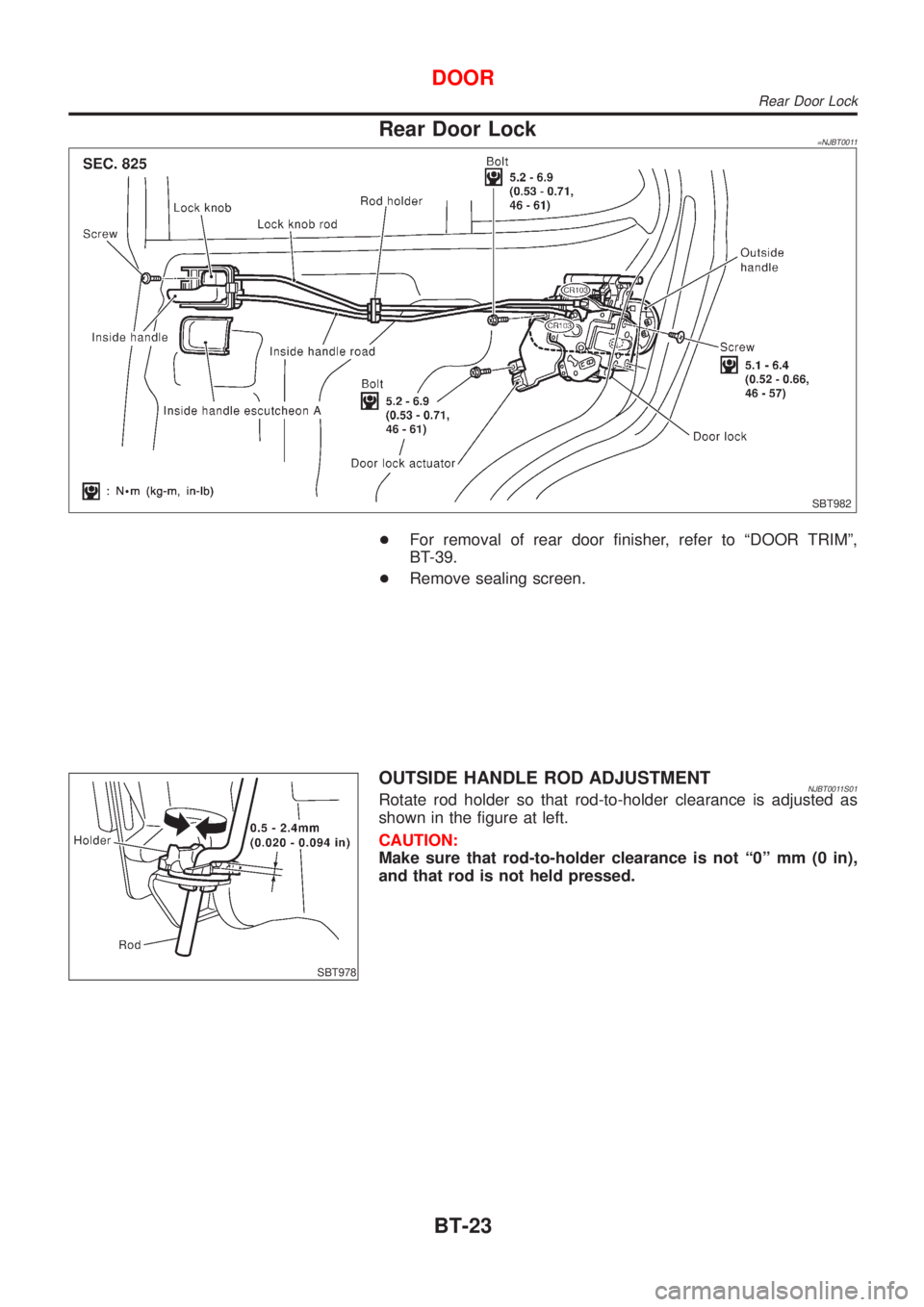
Rear Door Lock=NJBT0011
SBT982
+For removal of rear door finisher, refer to ªDOOR TRIMº,
BT-39.
+Remove sealing screen.
SBT978
OUTSIDE HANDLE ROD ADJUSTMENTNJBT0011S01Rotate rod holder so that rod-to-holder clearance is adjusted as
shown in the figure at left.
CAUTION:
Make sure that rod-to-holder clearance is not ª0º mm (0 in),
and that rod is not held pressed.
DOOR
Rear Door Lock
BT-23
Page 1918 of 2493
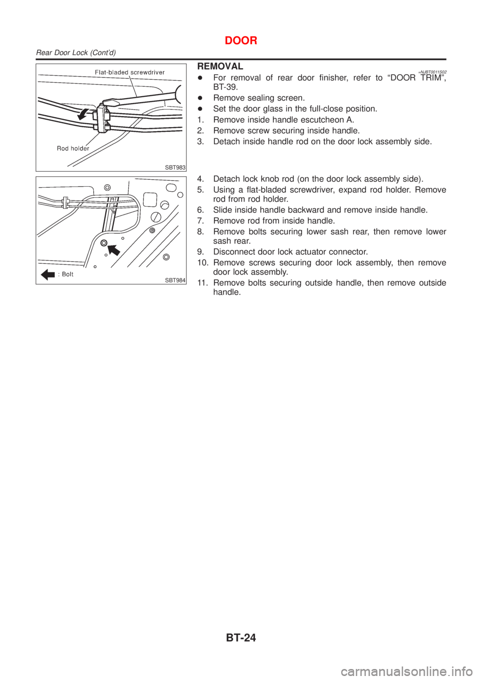
SBT983
REMOVAL=NJBT0011S02+For removal of rear door finisher, refer to ªDOOR TRIMº,
BT-39.
+Remove sealing screen.
+Set the door glass in the full-close position.
1. Remove inside handle escutcheon A.
2. Remove screw securing inside handle.
3. Detach inside handle rod on the door lock assembly side.
SBT984
4. Detach lock knob rod (on the door lock assembly side).
5. Using a flat-bladed screwdriver, expand rod holder. Remove
rod from rod holder.
6. Slide inside handle backward and remove inside handle.
7. Remove rod from inside handle.
8. Remove bolts securing lower sash rear, then remove lower
sash rear.
9. Disconnect door lock actuator connector.
10. Remove screws securing door lock assembly, then remove
door lock assembly.
11. Remove bolts securing outside handle, then remove outside
handle.
DOOR
Rear Door Lock (Cont'd)
BT-24