dtc 34 NISSAN ALMERA N16 2001 Electronic Repair Manual
[x] Cancel search | Manufacturer: NISSAN, Model Year: 2001, Model line: ALMERA N16, Model: NISSAN ALMERA N16 2001Pages: 2493, PDF Size: 66.97 MB
Page 19 of 2493
AGI070
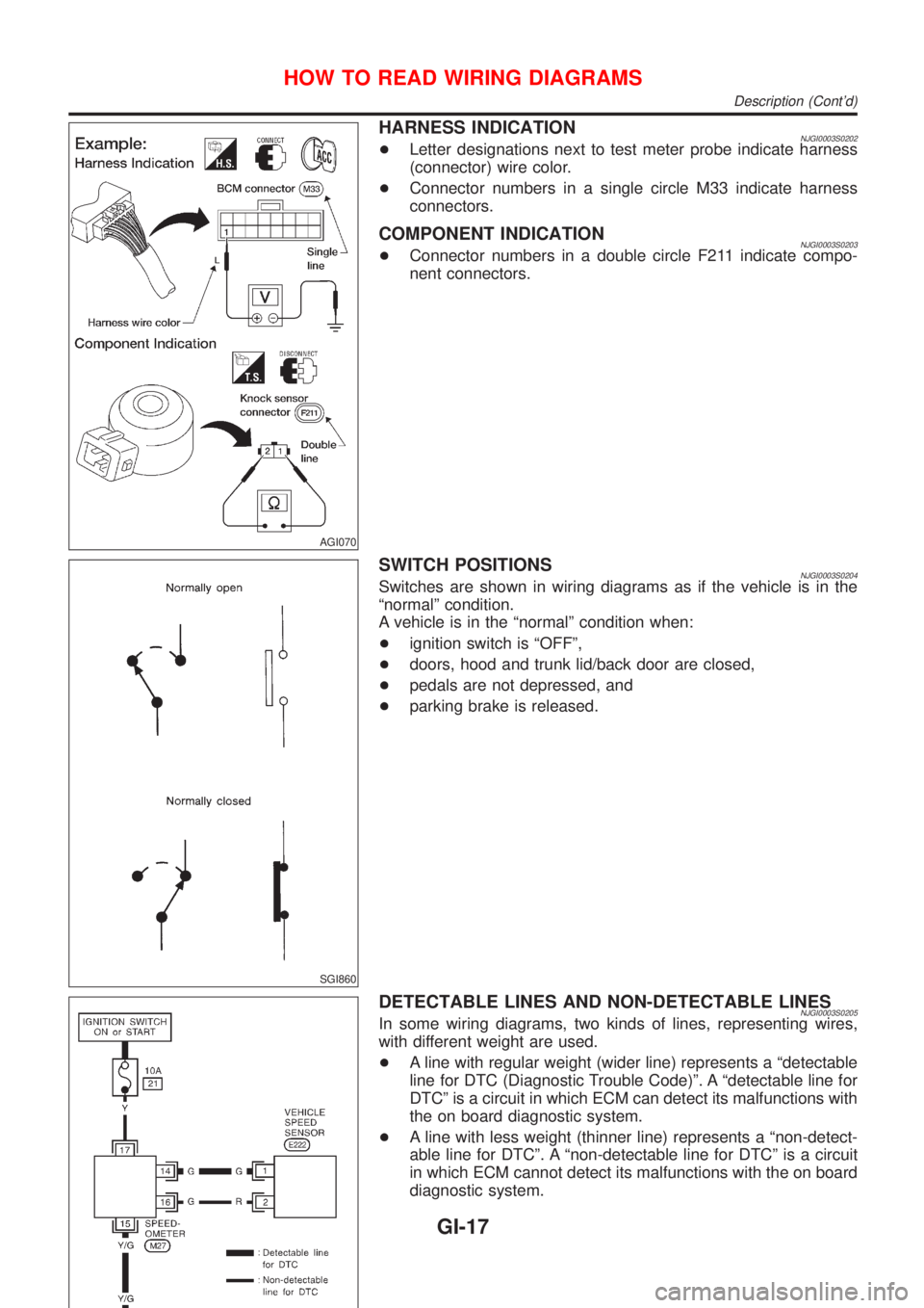
HARNESS INDICATIONNJGI0003S0202+Letter designations next to test meter probe indicate harness
(connector) wire color.
+Connector numbers in a single circle M33 indicate harness
connectors.
COMPONENT INDICATIONNJGI0003S0203+Connector numbers in a double circle F211 indicate compo-
nent connectors.
SGI860
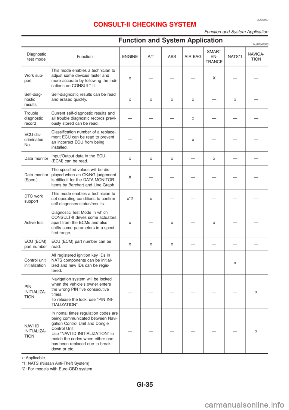
SWITCH POSITIONSNJGI0003S0204Switches are shown in wiring diagrams as if the vehicle is in the
ªnormalº condition.
A vehicle is in the ªnormalº condition when:
+ignition switch is ªOFFº,
+doors, hood and trunk lid/back door are closed,
+pedals are not depressed, and
+parking brake is released.
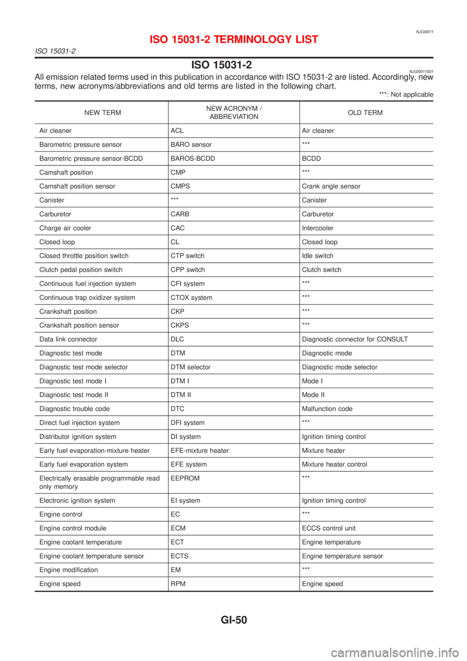
DETECTABLE LINES AND NON-DETECTABLE LINESNJGI0003S0205In some wiring diagrams, two kinds of lines, representing wires,
with different weight are used.
+A line with regular weight (wider line) represents a ªdetectable
line for DTC (Diagnostic Trouble Code)º. A ªdetectable line for
DTCº is a circuit in which ECM can detect its malfunctions with
the on board diagnostic system.
+A line with less weight (thinner line) represents a ªnon-detect-
able line for DTCº. A ªnon-detectable line for DTCº is a circuit
in which ECM cannot detect its malfunctions with the on board
diagnostic system.
HOW TO READ WIRING DIAGRAMS
Description (Cont'd)
GI-17
Page 37 of 2493
NJGI0007
Function and System ApplicationNJGI0007S05
Diagnostic
test modeFunction ENGINE A/T ABS AIR BAGSMART
EN-
TRANCENATS*1NAVIGA-
TION
Work sup-
portThis mode enables a technician to
adjust some devices faster and
more accurate by following the indi-
cations on CONSULT-II.x ÐÐÐXÐÐ
Self-diag-
nostic
resultsSelf-diagnostic results can be read
and erased quickly.x x x xÐxÐ
Trouble
diagnostic
recordCurrent self-diagnostic results and
all trouble diagnostic records previ-
ously stored can be read.ÐÐÐ x ÐÐÐ
ECU dis-
criminated
No.Classification number of a replace-
ment ECU can be read to prevent
an incorrect ECU from being
installed.ÐÐÐ x ÐÐÐ
Data monitorInput/Output data in the ECU
(ECM) can be read.x x xÐxÐÐ
Data monitor
(Spec.)The specified values will be dis-
played when an OK/NG judgement
is difficult for the DATA MONITOR
items by Barchart and Line Graph.X ÐÐÐÐÐÐ
DTC work
supportThis mode enables a technician to
set operating conditions to confirm
self-diagnoses status/results.x*2x ÐÐÐÐÐ
Active testDiagnostic Test Mode in which
CONSULT-II drives some actuators
apart from the ECMs and also
shifts some parameters in a speci-
fied range.xÐxÐxÐÐ
ECU (ECM)
part numberECU (ECM) part number can be
read.x x x ÐÐÐÐ
Control unit
initializationAll registered ignition key IDs in
NATS components can be initial-
ized and new IDs can be regis-
tered.ÐÐÐÐÐ x Ð
PIN
INITIALIZA-
TIONNavigation system will be locked
when the vehicle's owner enters
the wrong PIN five consecutive
times.
To release the lock, use ªPIN INI-
TIALIZATIONº.ÐÐÐÐÐÐ x
NAVI ID
INITIALIZA-
TIONIn nomal times regulation codes are
being communicated between Navi-
gation Control Unit and Dongle
Control Unit.
Use ªNAVI ID INITIALIZATIONº to
match the codes when either one
has been replaced due to break-
down or etc.ÐÐÐÐÐÐ x
x: Applicable
*1: NATS (Nissan Anti-Theft System)
*2: For models with Euro-OBD system
CONSULT-II CHECKING SYSTEM
Function and System Application
GI-35
Page 52 of 2493
NJGI0011
ISO 15031-2NJGI0011S01All emission related terms used in this publication in accordance with ISO 15031-2 are listed. Accordingly, new
terms, new acronyms/abbreviations and old terms are listed in the following chart.
***: Not applicable
NEW TERMNEW ACRONYM /
ABBREVIATIONOLD TERM
Air cleaner ACL Air cleaner
Barometric pressure sensor BARO sensor ***
Barometric pressure sensor-BCDD BAROS-BCDD BCDD
Camshaft position CMP ***
Camshaft position sensor CMPS Crank angle sensor
Canister *** Canister
Carburetor CARB Carburetor
Charge air cooler CAC Intercooler
Closed loop CL Closed loop
Closed throttle position switch CTP switch Idle switch
Clutch pedal position switch CPP switch Clutch switch
Continuous fuel injection system CFI system ***
Continuous trap oxidizer system CTOX system ***
Crankshaft position CKP ***
Crankshaft position sensor CKPS ***
Data link connector DLC Diagnostic connector for CONSULT
Diagnostic test mode DTM Diagnostic mode
Diagnostic test mode selector DTM selector Diagnostic mode selector
Diagnostic test mode I DTM I Mode I
Diagnostic test mode II DTM II Mode II
Diagnostic trouble code DTC Malfunction code
Direct fuel injection system DFI system ***
Distributor ignition system DI system Ignition timing control
Early fuel evaporation-mixture heater EFE-mixture heater Mixture heater
Early fuel evaporation system EFE system Mixture heater control
Electrically erasable programmable read
only memoryEEPROM ***
Electronic ignition system EI system Ignition timing control
Engine control EC ***
Engine control module ECM ECCS control unit
Engine coolant temperature ECT Engine temperature
Engine coolant temperature sensor ECTS Engine temperature sensor
Engine modification EM ***
Engine speed RPM Engine speed
ISO 15031-2 TERMINOLOGY LIST
ISO 15031-2
GI-50
Page 92 of 2493
NJEM0007
1. Warm up engine.
2. Turn ignition switch OFF.
3. Release fuel pressure.
Refer to EC-38, ªReleasing Fuel Pressureº.
4. Remove ignition coils.
5. Remove spark plugs.
+Clean area around plug with compressed air before removing
the spark plug.
SEM973E
AEM308
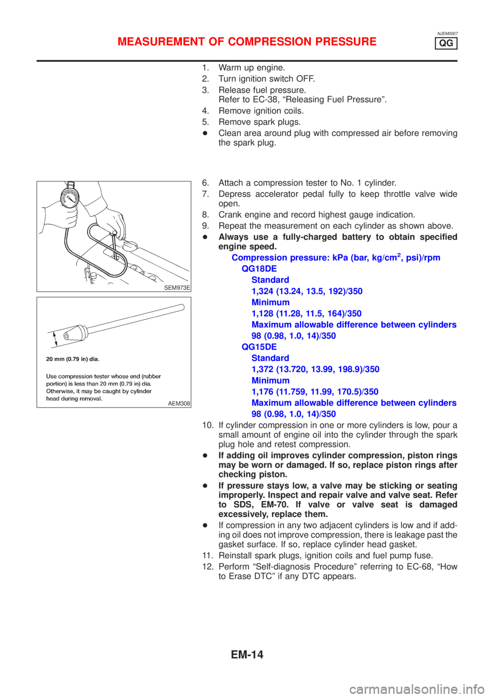
6. Attach a compression tester to No. 1 cylinder.
7. Depress accelerator pedal fully to keep throttle valve wide
open.
8. Crank engine and record highest gauge indication.
9. Repeat the measurement on each cylinder as shown above.
+Always use a fully-charged battery to obtain specified
engine speed.
Compression pressure: kPa (bar, kg/cm
2, psi)/rpm
QG18DE
Standard
1,324 (13.24, 13.5, 192)/350
Minimum
1,128 (11.28, 11.5, 164)/350
Maximum allowable difference between cylinders
98 (0.98, 1.0, 14)/350
QG15DE
Standard
1,372 (13.720, 13.99, 198.9)/350
Minimum
1,176 (11.759, 11.99, 170.5)/350
Maximum allowable difference between cylinders
98 (0.98, 1.0, 14)/350
10. If cylinder compression in one or more cylinders is low, pour a
small amount of engine oil into the cylinder through the spark
plug hole and retest compression.
+If adding oil improves cylinder compression, piston rings
may be worn or damaged. If so, replace piston rings after
checking piston.
+If pressure stays low, a valve may be sticking or seating
improperly. Inspect and repair valve and valve seat. Refer
to SDS, EM-70. If valve or valve seat is damaged
excessively, replace them.
+If compression in any two adjacent cylinders is low and if add-
ing oil does not improve compression, there is leakage past the
gasket surface. If so, replace cylinder head gasket.
11. Reinstall spark plugs, ignition coils and fuel pump fuse.
12. Perform ªSelf-diagnosis Procedureº referring to EC-68, ªHow
to Erase DTCº if any DTC appears.
MEASUREMENT OF COMPRESSION PRESSUREQG
EM-14
Page 297 of 2493
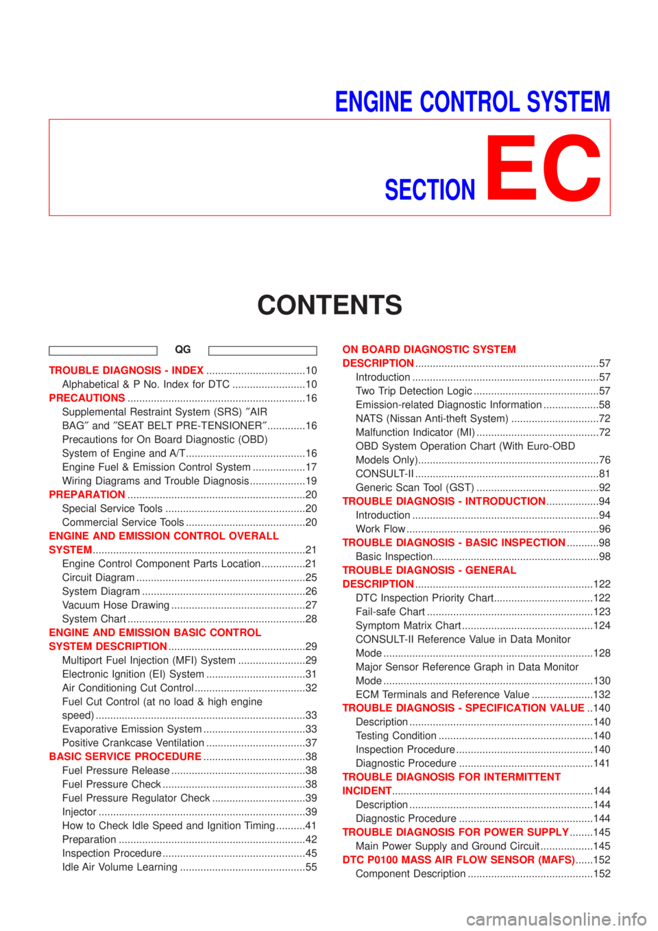
ENGINE CONTROL SYSTEM
SECTION
EC
CONTENTS
QG
TROUBLE DIAGNOSIS - INDEX..................................10
Alphabetical & P No. Index for DTC .........................10
PRECAUTIONS.............................................................16
Supplemental Restraint System (SRS)²AIR
BAG²and²SEAT BELT PRE-TENSIONER².............16
Precautions for On Board Diagnostic (OBD)
System of Engine and A/T.........................................16
Engine Fuel & Emission Control System ..................17
Wiring Diagrams and Trouble Diagnosis ...................19
PREPARATION.............................................................20
Special Service Tools ................................................20
Commercial Service Tools .........................................20
ENGINE AND EMISSION CONTROL OVERALL
SYSTEM.........................................................................21
Engine Control Component Parts Location ...............21
Circuit Diagram ..........................................................25
System Diagram ........................................................26
Vacuum Hose Drawing ..............................................27
System Chart .............................................................28
ENGINE AND EMISSION BASIC CONTROL
SYSTEM DESCRIPTION...............................................29
Multiport Fuel Injection (MFI) System .......................29
Electronic Ignition (EI) System ..................................31
Air Conditioning Cut Control ......................................32
Fuel Cut Control (at no load & high engine
speed) ........................................................................33
Evaporative Emission System ...................................33
Positive Crankcase Ventilation ..................................37
BASIC SERVICE PROCEDURE...................................38
Fuel Pressure Release ..............................................38
Fuel Pressure Check .................................................38
Fuel Pressure Regulator Check ................................39
Injector .......................................................................39
How to Check Idle Speed and Ignition Timing ..........41
Preparation ................................................................42
Inspection Procedure .................................................45
Idle Air Volume Learning ...........................................55ON BOARD DIAGNOSTIC SYSTEM
DESCRIPTION...............................................................57
Introduction ................................................................57
Two Trip Detection Logic ...........................................57
Emission-related Diagnostic Information ...................58
NATS (Nissan Anti-theft System) ..............................72
Malfunction Indicator (MI) ..........................................72
OBD System Operation Chart (With Euro-OBD
Models Only)..............................................................76
CONSULT-II ...............................................................81
Generic Scan Tool (GST) ..........................................92
TROUBLE DIAGNOSIS - INTRODUCTION..................94
Introduction ................................................................94
Work Flow ..................................................................96
TROUBLE DIAGNOSIS - BASIC INSPECTION...........98
Basic Inspection.........................................................98
TROUBLE DIAGNOSIS - GENERAL
DESCRIPTION.............................................................122
DTC Inspection Priority Chart..................................122
Fail-safe Chart .........................................................123
Symptom Matrix Chart .............................................124
CONSULT-II Reference Value in Data Monitor
Mode ........................................................................128
Major Sensor Reference Graph in Data Monitor
Mode ........................................................................130
ECM Terminals and Reference Value .....................132
TROUBLE DIAGNOSIS - SPECIFICATION VALUE..140
Description ...............................................................140
Testing Condition .....................................................140
Inspection Procedure ...............................................140
Diagnostic Procedure ..............................................141
TROUBLE DIAGNOSIS FOR INTERMITTENT
INCIDENT.....................................................................144
Description ...............................................................144
Diagnostic Procedure ..............................................144
TROUBLE DIAGNOSIS FOR POWER SUPPLY........145
Main Power Supply and Ground Circuit ..................145
DTC P0100 MASS AIR FLOW SENSOR (MAFS)......152
Component Description ...........................................152
Page 298 of 2493
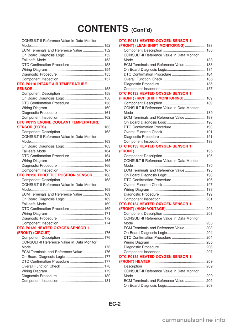
CONSULT-II Reference Value in Data Monitor
Mode ........................................................................152
ECM Terminals and Reference Value .....................152
On Board Diagnosis Logic.......................................152
Fail-safe Mode .........................................................153
DTC Confirmation Procedure ..................................153
Wiring Diagram ........................................................154
Diagnostic Procedure ..............................................155
Component Inspection .............................................157
DTC P0110 INTAKE AIR TEMPERATURE
SENSOR......................................................................158
Component Description ...........................................158
On Board Diagnosis Logic.......................................158
DTC Confirmation Procedure ..................................158
Wiring Diagram ........................................................160
Diagnostic Procedure ..............................................161
Component Inspection .............................................162
DTC P0115 ENGINE COOLANT TEMPERATURE
SENSOR (ECTS).........................................................163
Component Description ...........................................163
CONSULT-II Reference Value in Data Monitor
Mode ........................................................................163
On Board Diagnosis Logic.......................................163
Fail-safe Mode .........................................................164
DTC Confirmation Procedure ..................................164
Wiring Diagram ........................................................165
Diagnostic Procedure ..............................................166
Component Inspection .............................................167
DTC P0120 THROTTLE POSITION SENSOR...........168
Component Description ...........................................168
CONSULT-II Reference Value in Data Monitor
Mode ........................................................................168
ECM Terminals and Reference Value .....................169
On Board Diagnosis Logic.......................................169
Fail-safe Mode .........................................................169
DTC Confirmation Procedure ..................................169
Wiring Diagram ........................................................171
Diagnostic Procedure ..............................................172
Component Inspection .............................................174
DTC P0130 HEATED OXYGEN SENSOR 1
(FRONT) (CIRCUIT).....................................................176
Component Description ...........................................176
CONSULT-II Reference Value in Data Monitor
Mode ........................................................................176
ECM Terminals and Reference Value .....................176
On Board Diagnosis Logic.......................................177
DTC Confirmation Procedure ..................................177
Overall Function Check ...........................................178
Wiring Diagram ........................................................179
Diagnostic Procedure ..............................................180
Component Inspection .............................................181DTC P0131 HEATED OXYGEN SENSOR 1
(FRONT) (LEAN SHIFT MONITORING).....................183
Component Description ...........................................183
CONSULT-II Reference Value in Data Monitor
Mode ........................................................................183
ECM Terminals and Reference Value .....................183
On Board Diagnosis Logic.......................................184
DTC Confirmation Procedure ..................................184
Overall Function Check ...........................................185
Diagnostic Procedure ..............................................185
Component Inspection .............................................187
DTC P0132 HEATED OXYGEN SENSOR 1
(FRONT) (RICH SHIFT MONITORING)......................189
Component Description ...........................................189
CONSULT-II Reference Value in Data Monitor
Mode ........................................................................189
ECM Terminals and Reference Value .....................189
On Board Diagnosis Logic.......................................190
DTC Confirmation Procedure ..................................190
Overall Function Check ...........................................191
Diagnostic Procedure ..............................................191
Component Inspection .............................................193
DTC P0133 HEATED OXYGEN SENSOR 1
(FRONT).......................................................................195
Component Description ...........................................195
CONSULT-II Reference Value in Data Monitor
Mode ........................................................................195
ECM Terminals and Reference Value .....................195
On Board Diagnosis Logic.......................................196
DTC Confirmation Procedure ..................................196
Overall Function Check ...........................................197
Wiring Diagram ........................................................198
Diagnostic Procedure ..............................................199
Component Inspection .............................................201
DTC P0134 HEATED OXYGEN SENSOR 1
(FRONT) (HIGH VOLTAGE)........................................203
Component Description ...........................................203
CONSULT-II Reference Value in Data Monitor
Mode ........................................................................203
ECM Terminals and Reference Value .....................203
On Board Diagnosis Logic.......................................204
DTC Confirmation Procedure ..................................204
Wiring Diagram ........................................................205
Diagnostic Procedure ..............................................206
Component Inspection .............................................207
DTC P0135 HEATED OXYGEN SENSOR 1
(FRONT) HEATER.......................................................209
Description ...............................................................209
CONSULT-II Reference Value in Data Monitor
Mode ........................................................................209
ECM Terminals and Reference Value .....................209
On Board Diagnosis Logic.......................................209
CONTENTS(Cont'd)
EC-2
Page 299 of 2493
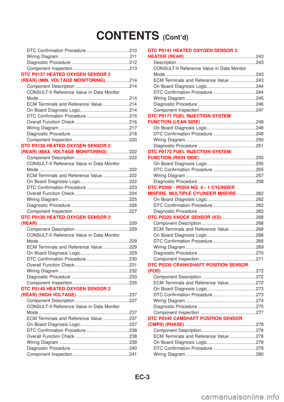
DTC Confirmation Procedure ..................................210
Wiring Diagram ........................................................ 211
Diagnostic Procedure ..............................................212
Component Inspection .............................................213
DTC P0137 HEATED OXYGEN SENSOR 2
(REAR) (MIN. VOLTAGE MONITORING)...................214
Component Description ...........................................214
CONSULT-II Reference Value in Data Monitor
Mode ........................................................................214
ECM Terminals and Reference Value .....................214
On Board Diagnosis Logic.......................................214
DTC Confirmation Procedure ..................................215
Overall Function Check ...........................................216
Wiring Diagram ........................................................217
Diagnostic Procedure ..............................................218
Component Inspection .............................................220
DTC P0138 HEATED OXYGEN SENSOR 2
(REAR) (MAX. VOLTAGE MONITORING).................222
Component Description ...........................................222
CONSULT-II Reference Value in Data Monitor
Mode ........................................................................222
ECM Terminals and Reference Value .....................222
On Board Diagnosis Logic.......................................222
DTC Confirmation Procedure ..................................223
Overall Function Check ...........................................224
Wiring Diagram ........................................................225
Diagnostic Procedure ..............................................226
Component Inspection .............................................227
DTC P0139 HEATED OXYGEN SENSOR 2
(REAR).........................................................................229
Component Description ...........................................229
CONSULT-II Reference Value in Data Monitor
Mode ........................................................................229
ECM Terminals and Reference Value .....................229
On Board Diagnosis Logic.......................................229
DTC Confirmation Procedure ..................................230
Overall Function Check ...........................................231
Wiring Diagram ........................................................232
Diagnostic Procedure ..............................................233
Component Inspection .............................................235
DTC P0140 HEATED OXYGEN SENSOR 2
(REAR) (HIGH VOLTAGE)..........................................237
Component Description ...........................................237
CONSULT-II Reference Value in Data Monitor
Mode ........................................................................237
ECM Terminals and Reference Value .....................237
On Board Diagnosis Logic.......................................237
DTC Confirmation Procedure ..................................238
Overall Function Check ...........................................238
Wiring Diagram ........................................................239
Diagnostic Procedure ..............................................240
Component Inspection .............................................241DTC P0141 HEATED OXYGEN SENSOR 2
HEATER (REAR).........................................................243
Description ...............................................................243
CONSULT-II Reference Value in Data Monitor
Mode ........................................................................243
ECM Terminals and Reference Value .....................243
On Board Diagnosis Logic.......................................244
DTC Confirmation Procedure ..................................244
Wiring Diagram ........................................................245
Diagnostic Procedure ..............................................246
Component Inspection .............................................247
DTC P0171 FUEL INJECTION SYSTEM
FUNCTION (LEAN SIDE)............................................248
On Board Diagnosis Logic.......................................248
DTC Confirmation Procedure ..................................248
Wiring Diagram ........................................................250
Diagnostic Procedure ..............................................251
DTC P0172 FUEL INJECTION SYSTEM
FUNCTION (RICH SIDE).............................................255
On Board Diagnosis Logic.......................................255
DTC Confirmation Procedure ..................................255
Wiring Diagram ........................................................257
Diagnostic Procedure ..............................................258
DTC P0300 - P0304 NO.4-1CYLINDER
MISFIRE, MULTIPLE CYLINDER MISFIRE...............262
On Board Diagnosis Logic.......................................262
DTC Confirmation Procedure ..................................262
Diagnostic Procedure ..............................................263
DTC P0325 KNOCK SENSOR (KS)...........................268
Component Description ...........................................268
ECM Terminals and Reference Value .....................268
On Board Diagnosis Logic.......................................268
DTC Confirmation Procedure ..................................268
Wiring Diagram ........................................................269
Diagnostic Procedure ..............................................270
Component Inspection .............................................271
DTC P0335 CRANKSHAFT POSITION SENSOR
(POS)............................................................................272
Component Description ...........................................272
ECM Terminals and Reference Value .....................272
On Board Diagnosis Logic.......................................273
DTC Confirmation Procedure ..................................273
Wiring Diagram ........................................................274
Diagnostic Procedure ..............................................275
Component Inspection .............................................277
DTC P0340 CAMSHAFT POSITION SENSOR
(CMPS) (PHASE).........................................................278
Component Description ...........................................278
ECM Terminals and Reference Value .....................278
On Board Diagnosis Logic.......................................279
DTC Confirmation Procedure ..................................279
Wiring Diagram ........................................................280
CONTENTS(Cont'd)
EC-3
Page 300 of 2493
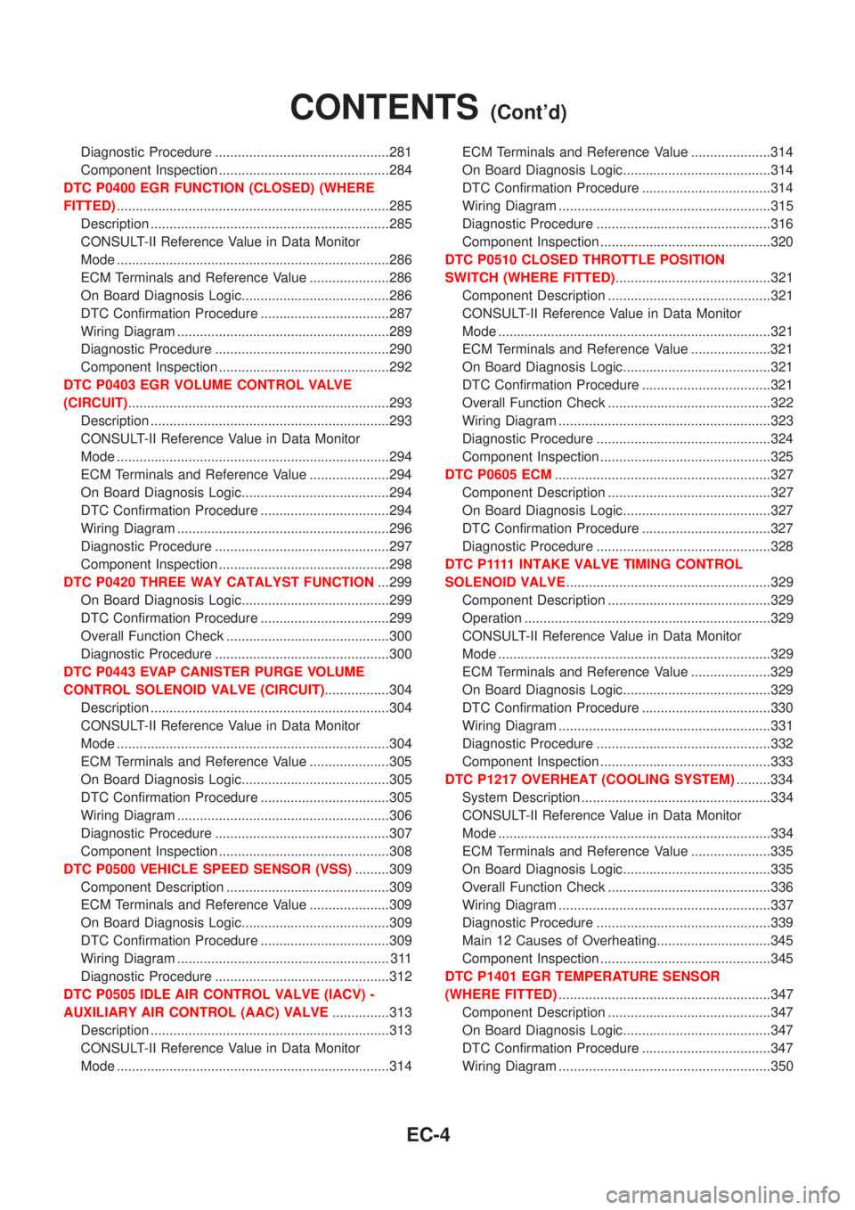
Diagnostic Procedure ..............................................281
Component Inspection .............................................284
DTC P0400 EGR FUNCTION (CLOSED) (WHERE
FITTED)........................................................................285
Description ...............................................................285
CONSULT-II Reference Value in Data Monitor
Mode ........................................................................286
ECM Terminals and Reference Value .....................286
On Board Diagnosis Logic.......................................286
DTC Confirmation Procedure ..................................287
Wiring Diagram ........................................................289
Diagnostic Procedure ..............................................290
Component Inspection .............................................292
DTC P0403 EGR VOLUME CONTROL VALVE
(CIRCUIT).....................................................................293
Description ...............................................................293
CONSULT-II Reference Value in Data Monitor
Mode ........................................................................294
ECM Terminals and Reference Value .....................294
On Board Diagnosis Logic.......................................294
DTC Confirmation Procedure ..................................294
Wiring Diagram ........................................................296
Diagnostic Procedure ..............................................297
Component Inspection .............................................298
DTC P0420 THREE WAY CATALYST FUNCTION...299
On Board Diagnosis Logic.......................................299
DTC Confirmation Procedure ..................................299
Overall Function Check ...........................................300
Diagnostic Procedure ..............................................300
DTC P0443 EVAP CANISTER PURGE VOLUME
CONTROL SOLENOID VALVE (CIRCUIT).................304
Description ...............................................................304
CONSULT-II Reference Value in Data Monitor
Mode ........................................................................304
ECM Terminals and Reference Value .....................305
On Board Diagnosis Logic.......................................305
DTC Confirmation Procedure ..................................305
Wiring Diagram ........................................................306
Diagnostic Procedure ..............................................307
Component Inspection .............................................308
DTC P0500 VEHICLE SPEED SENSOR (VSS).........309
Component Description ...........................................309
ECM Terminals and Reference Value .....................309
On Board Diagnosis Logic.......................................309
DTC Confirmation Procedure ..................................309
Wiring Diagram ........................................................ 311
Diagnostic Procedure ..............................................312
DTC P0505 IDLE AIR CONTROL VALVE (IACV) -
AUXILIARY AIR CONTROL (AAC) VALVE...............313
Description ...............................................................313
CONSULT-II Reference Value in Data Monitor
Mode ........................................................................314ECM Terminals and Reference Value .....................314
On Board Diagnosis Logic.......................................314
DTC Confirmation Procedure ..................................314
Wiring Diagram ........................................................315
Diagnostic Procedure ..............................................316
Component Inspection .............................................320
DTC P0510 CLOSED THROTTLE POSITION
SWITCH (WHERE FITTED).........................................321
Component Description ...........................................321
CONSULT-II Reference Value in Data Monitor
Mode ........................................................................321
ECM Terminals and Reference Value .....................321
On Board Diagnosis Logic.......................................321
DTC Confirmation Procedure ..................................321
Overall Function Check ...........................................322
Wiring Diagram ........................................................323
Diagnostic Procedure ..............................................324
Component Inspection .............................................325
DTC P0605 ECM.........................................................327
Component Description ...........................................327
On Board Diagnosis Logic.......................................327
DTC Confirmation Procedure ..................................327
Diagnostic Procedure ..............................................328
D T C P 1111INTAKE VALVE TIMING CONTROL
SOLENOID VALVE......................................................329
Component Description ...........................................329
Operation .................................................................329
CONSULT-II Reference Value in Data Monitor
Mode ........................................................................329
ECM Terminals and Reference Value .....................329
On Board Diagnosis Logic.......................................329
DTC Confirmation Procedure ..................................330
Wiring Diagram ........................................................331
Diagnostic Procedure ..............................................332
Component Inspection .............................................333
DTC P1217 OVERHEAT (COOLING SYSTEM).........334
System Description ..................................................334
CONSULT-II Reference Value in Data Monitor
Mode ........................................................................334
ECM Terminals and Reference Value .....................335
On Board Diagnosis Logic.......................................335
Overall Function Check ...........................................336
Wiring Diagram ........................................................337
Diagnostic Procedure ..............................................339
Main 12 Causes of Overheating..............................345
Component Inspection .............................................345
DTC P1401 EGR TEMPERATURE SENSOR
(WHERE FITTED)........................................................347
Component Description ...........................................347
On Board Diagnosis Logic.......................................347
DTC Confirmation Procedure ..................................347
Wiring Diagram ........................................................350
CONTENTS(Cont'd)
EC-4
Page 301 of 2493
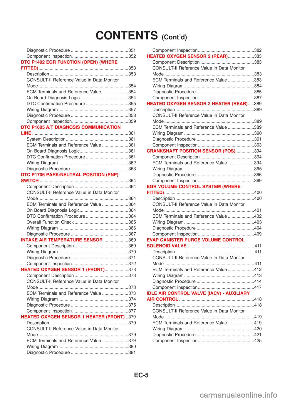
Diagnostic Procedure ..............................................351
Component Inspection .............................................352
DTC P1402 EGR FUNCTION (OPEN) (WHERE
FITTED)........................................................................353
Description ...............................................................353
CONSULT-II Reference Value in Data Monitor
Mode ........................................................................354
ECM Terminals and Reference Value .....................354
On Board Diagnosis Logic.......................................354
DTC Confirmation Procedure ..................................355
Wiring Diagram ........................................................357
Diagnostic Procedure ..............................................358
Component Inspection .............................................359
DTC P1605 A/T DIAGNOSIS COMMUNICATION
LINE.............................................................................361
System Description ..................................................361
ECM Terminals and Reference Value .....................361
On Board Diagnosis Logic.......................................361
DTC Confirmation Procedure ..................................361
Wiring Diagram ........................................................362
Diagnostic Procedure ..............................................363
DTC P1706 PARK/NEUTRAL POSITION (PNP)
SWITCH.......................................................................364
Component Description ...........................................364
CONSULT-II Reference Value in Data Monitor
Mode ........................................................................364
ECM Terminals and Reference Value .....................364
On Board Diagnosis Logic.......................................364
DTC Confirmation Procedure ..................................364
Overall Function Check ...........................................365
Wiring Diagram ........................................................366
Diagnostic Procedure ..............................................367
INTAKE AIR TEMPERATURE SENSOR....................369
Component Description ...........................................369
Wiring Diagram ........................................................370
Diagnostic Procedure ..............................................371
Component Inspection .............................................372
HEATED OXYGEN SENSOR 1 (FRONT)...................373
Component Description ...........................................373
CONSULT-II Reference Value in Data Monitor
Mode ........................................................................373
ECM Terminals and Reference Value .....................373
Wiring Diagram ........................................................374
Diagnostic Procedure ..............................................375
Component Inspection .............................................377
HEATED OXYGEN SENSOR 1 HEATER (FRONT)...379
Description ...............................................................379
CONSULT-II Reference Value in Data Monitor
Mode ........................................................................379
ECM Terminals and Reference Value .....................379
Wiring Diagram ........................................................380
Diagnostic Procedure ..............................................381Component Inspection .............................................382
HEATED OXYGEN SENSOR 2 (REAR).....................383
Component Description ...........................................383
CONSULT-II Reference Value in Data Monitor
Mode ........................................................................383
ECM Terminals and Reference Value .....................383
Wiring Diagram ........................................................384
Diagnostic Procedure ..............................................385
Component Inspection .............................................387
HEATED OXYGEN SENSOR 2 HEATER (REAR).....389
Description ...............................................................389
CONSULT-II Reference Value in Data Monitor
Mode ........................................................................389
ECM Terminals and Reference Value .....................389
Wiring Diagram ........................................................390
Diagnostic Procedure ..............................................391
Component Inspection .............................................393
CRANKSHAFT POSITION SENSOR (POS)...............394
Component Description ...........................................394
ECM Terminals and Reference Value .....................394
Wiring Diagram ........................................................395
Diagnostic Procedure ..............................................396
Component Inspection .............................................399
EGR VOLUME CONTROL SYSTEM (WHERE
FITTED)........................................................................400
Description ...............................................................400
CONSULT-II Reference Value in Data Monitor
Mode ........................................................................401
ECM Terminals and Reference Value .....................402
Wiring Diagram ........................................................403
Diagnostic Procedure ..............................................404
Component Inspection .............................................409
EVAP CANISTER PURGE VOLUME CONTROL
SOLENOID VALVE...................................................... 411
Description ............................................................... 411
CONSULT-II Reference Value in Data Monitor
Mode ........................................................................ 411
ECM Terminals and Reference Value .....................412
Wiring Diagram ........................................................413
Diagnostic Procedure ..............................................414
Component Inspection .............................................417
IDLE AIR CONTROL VALVE (IACV) - AUXILIARY
AIR CONTROL............................................................418
Description ...............................................................418
CONSULT-II Reference Value in Data Monitor
Mode ........................................................................419
ECM Terminals and Reference Value .....................419
Wiring Diagram ........................................................420
Diagnostic Procedure ..............................................421
Component Inspection .............................................425
CONTENTS(Cont'd)
EC-5
Page 303 of 2493
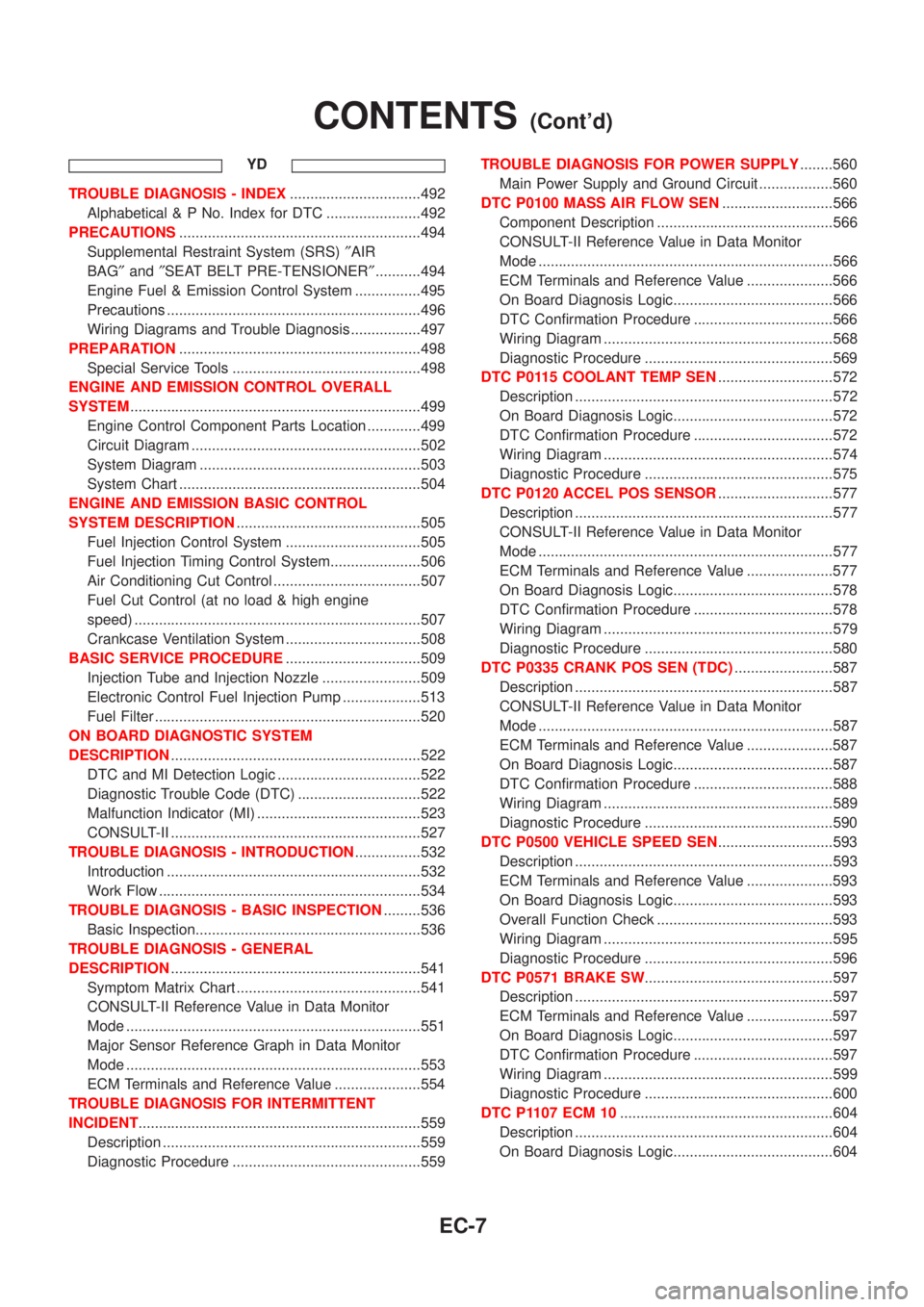
YD
TROUBLE DIAGNOSIS - INDEX................................492
Alphabetical & P No. Index for DTC .......................492
PRECAUTIONS...........................................................494
Supplemental Restraint System (SRS)²AIR
BAG²and²SEAT BELT PRE-TENSIONER²...........494
Engine Fuel & Emission Control System ................495
Precautions ..............................................................496
Wiring Diagrams and Trouble Diagnosis .................497
PREPARATION...........................................................498
Special Service Tools ..............................................498
ENGINE AND EMISSION CONTROL OVERALL
SYSTEM.......................................................................499
Engine Control Component Parts Location .............499
Circuit Diagram ........................................................502
System Diagram ......................................................503
System Chart ...........................................................504
ENGINE AND EMISSION BASIC CONTROL
SYSTEM DESCRIPTION.............................................505
Fuel Injection Control System .................................505
Fuel Injection Timing Control System......................506
Air Conditioning Cut Control ....................................507
Fuel Cut Control (at no load & high engine
speed) ......................................................................507
Crankcase Ventilation System .................................508
BASIC SERVICE PROCEDURE.................................509
Injection Tube and Injection Nozzle ........................509
Electronic Control Fuel Injection Pump ...................513
Fuel Filter .................................................................520
ON BOARD DIAGNOSTIC SYSTEM
DESCRIPTION.............................................................522
DTC and MI Detection Logic ...................................522
Diagnostic Trouble Code (DTC) ..............................522
Malfunction Indicator (MI) ........................................523
CONSULT-II .............................................................527
TROUBLE DIAGNOSIS - INTRODUCTION................532
Introduction ..............................................................532
Work Flow ................................................................534
TROUBLE DIAGNOSIS - BASIC INSPECTION.........536
Basic Inspection.......................................................536
TROUBLE DIAGNOSIS - GENERAL
DESCRIPTION.............................................................541
Symptom Matrix Chart .............................................541
CONSULT-II Reference Value in Data Monitor
Mode ........................................................................551
Major Sensor Reference Graph in Data Monitor
Mode ........................................................................553
ECM Terminals and Reference Value .....................554
TROUBLE DIAGNOSIS FOR INTERMITTENT
INCIDENT.....................................................................559
Description ...............................................................559
Diagnostic Procedure ..............................................559TROUBLE DIAGNOSIS FOR POWER SUPPLY........560
Main Power Supply and Ground Circuit ..................560
DTC P0100 MASS AIR FLOW SEN...........................566
Component Description ...........................................566
CONSULT-II Reference Value in Data Monitor
Mode ........................................................................566
ECM Terminals and Reference Value .....................566
On Board Diagnosis Logic.......................................566
DTC Confirmation Procedure ..................................566
Wiring Diagram ........................................................568
Diagnostic Procedure ..............................................569
DTC P0115 COOLANT TEMP SEN............................572
Description ...............................................................572
On Board Diagnosis Logic.......................................572
DTC Confirmation Procedure ..................................572
Wiring Diagram ........................................................574
Diagnostic Procedure ..............................................575
DTC P0120 ACCEL POS SENSOR............................577
Description ...............................................................577
CONSULT-II Reference Value in Data Monitor
Mode ........................................................................577
ECM Terminals and Reference Value .....................577
On Board Diagnosis Logic.......................................578
DTC Confirmation Procedure ..................................578
Wiring Diagram ........................................................579
Diagnostic Procedure ..............................................580
DTC P0335 CRANK POS SEN (TDC)........................587
Description ...............................................................587
CONSULT-II Reference Value in Data Monitor
Mode ........................................................................587
ECM Terminals and Reference Value .....................587
On Board Diagnosis Logic.......................................587
DTC Confirmation Procedure ..................................588
Wiring Diagram ........................................................589
Diagnostic Procedure ..............................................590
DTC P0500 VEHICLE SPEED SEN............................593
Description ...............................................................593
ECM Terminals and Reference Value .....................593
On Board Diagnosis Logic.......................................593
Overall Function Check ...........................................593
Wiring Diagram ........................................................595
Diagnostic Procedure ..............................................596
DTC P0571 BRAKE SW..............................................597
Description ...............................................................597
ECM Terminals and Reference Value .....................597
On Board Diagnosis Logic.......................................597
DTC Confirmation Procedure ..................................597
Wiring Diagram ........................................................599
Diagnostic Procedure ..............................................600
DTC P1107 ECM 10....................................................604
Description ...............................................................604
On Board Diagnosis Logic.......................................604
CONTENTS(Cont'd)
EC-7