fuel injector NISSAN ALMERA N16 2001 Electronic Repair Manual
[x] Cancel search | Manufacturer: NISSAN, Model Year: 2001, Model line: ALMERA N16, Model: NISSAN ALMERA N16 2001Pages: 2493, PDF Size: 66.97 MB
Page 8 of 2493
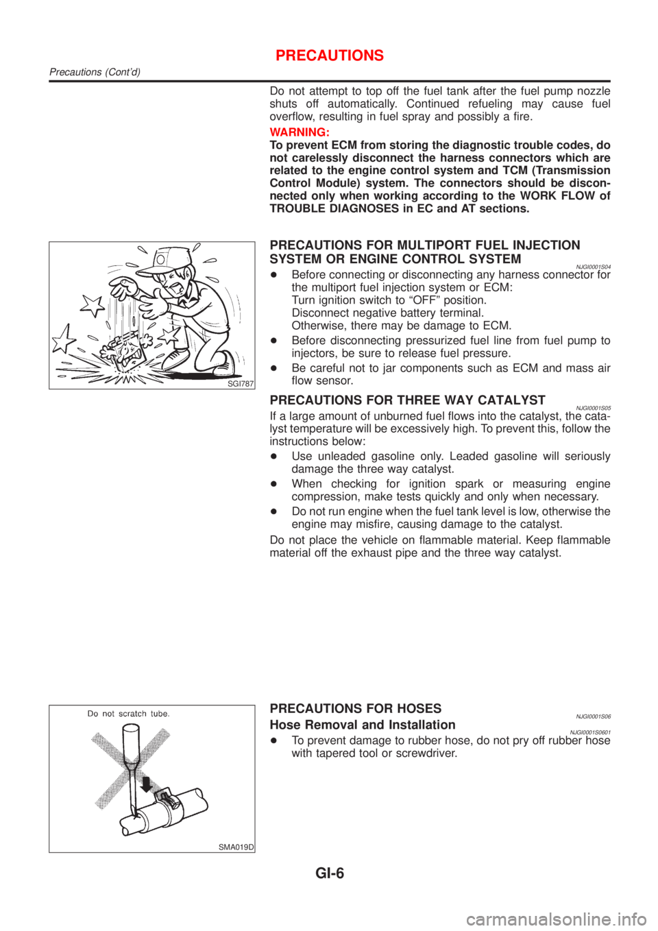
Do not attempt to top off the fuel tank after the fuel pump nozzle
shuts off automatically. Continued refueling may cause fuel
overflow, resulting in fuel spray and possibly a fire.
WARNING:
To prevent ECM from storing the diagnostic trouble codes, do
not carelessly disconnect the harness connectors which are
related to the engine control system and TCM (Transmission
Control Module) system. The connectors should be discon-
nected only when working according to the WORK FLOW of
TROUBLE DIAGNOSES in EC and AT sections.
SGI787
PRECAUTIONS FOR MULTIPORT FUEL INJECTION
SYSTEM OR ENGINE CONTROL SYSTEM
NJGI0001S04+Before connecting or disconnecting any harness connector for
the multiport fuel injection system or ECM:
Turn ignition switch to ªOFFº position.
Disconnect negative battery terminal.
Otherwise, there may be damage to ECM.
+Before disconnecting pressurized fuel line from fuel pump to
injectors, be sure to release fuel pressure.
+Be careful not to jar components such as ECM and mass air
flow sensor.
PRECAUTIONS FOR THREE WAY CATALYSTNJGI0001S05If a large amount of unburned fuel flows into the catalyst, the cata-
lyst temperature will be excessively high. To prevent this, follow the
instructions below:
+Use unleaded gasoline only. Leaded gasoline will seriously
damage the three way catalyst.
+When checking for ignition spark or measuring engine
compression, make tests quickly and only when necessary.
+Do not run engine when the fuel tank level is low, otherwise the
engine may misfire, causing damage to the catalyst.
Do not place the vehicle on flammable material. Keep flammable
material off the exhaust pipe and the three way catalyst.
SMA019D
PRECAUTIONS FOR HOSESNJGI0001S06Hose Removal and InstallationNJGI0001S0601+To prevent damage to rubber hose, do not pry off rubber hose
with tapered tool or screwdriver.
PRECAUTIONS
Precautions (Cont'd)
GI-6
Page 297 of 2493
ENGINE CONTROL SYSTEM
SECTION
EC
CONTENTS
QG
TROUBLE DIAGNOSIS - INDEX..................................10
Alphabetical & P No. Index for DTC .........................10
PRECAUTIONS.............................................................16
Supplemental Restraint System (SRS)²AIR
BAG²and²SEAT BELT PRE-TENSIONER².............16
Precautions for On Board Diagnostic (OBD)
System of Engine and A/T.........................................16
Engine Fuel & Emission Control System ..................17
Wiring Diagrams and Trouble Diagnosis ...................19
PREPARATION.............................................................20
Special Service Tools ................................................20
Commercial Service Tools .........................................20
ENGINE AND EMISSION CONTROL OVERALL
SYSTEM.........................................................................21
Engine Control Component Parts Location ...............21
Circuit Diagram ..........................................................25
System Diagram ........................................................26
Vacuum Hose Drawing ..............................................27
System Chart .............................................................28
ENGINE AND EMISSION BASIC CONTROL
SYSTEM DESCRIPTION...............................................29
Multiport Fuel Injection (MFI) System .......................29
Electronic Ignition (EI) System ..................................31
Air Conditioning Cut Control ......................................32
Fuel Cut Control (at no load & high engine
speed) ........................................................................33
Evaporative Emission System ...................................33
Positive Crankcase Ventilation ..................................37
BASIC SERVICE PROCEDURE...................................38
Fuel Pressure Release ..............................................38
Fuel Pressure Check .................................................38
Fuel Pressure Regulator Check ................................39
Injector .......................................................................39
How to Check Idle Speed and Ignition Timing ..........41
Preparation ................................................................42
Inspection Procedure .................................................45
Idle Air Volume Learning ...........................................55ON BOARD DIAGNOSTIC SYSTEM
DESCRIPTION...............................................................57
Introduction ................................................................57
Two Trip Detection Logic ...........................................57
Emission-related Diagnostic Information ...................58
NATS (Nissan Anti-theft System) ..............................72
Malfunction Indicator (MI) ..........................................72
OBD System Operation Chart (With Euro-OBD
Models Only)..............................................................76
CONSULT-II ...............................................................81
Generic Scan Tool (GST) ..........................................92
TROUBLE DIAGNOSIS - INTRODUCTION..................94
Introduction ................................................................94
Work Flow ..................................................................96
TROUBLE DIAGNOSIS - BASIC INSPECTION...........98
Basic Inspection.........................................................98
TROUBLE DIAGNOSIS - GENERAL
DESCRIPTION.............................................................122
DTC Inspection Priority Chart..................................122
Fail-safe Chart .........................................................123
Symptom Matrix Chart .............................................124
CONSULT-II Reference Value in Data Monitor
Mode ........................................................................128
Major Sensor Reference Graph in Data Monitor
Mode ........................................................................130
ECM Terminals and Reference Value .....................132
TROUBLE DIAGNOSIS - SPECIFICATION VALUE..140
Description ...............................................................140
Testing Condition .....................................................140
Inspection Procedure ...............................................140
Diagnostic Procedure ..............................................141
TROUBLE DIAGNOSIS FOR INTERMITTENT
INCIDENT.....................................................................144
Description ...............................................................144
Diagnostic Procedure ..............................................144
TROUBLE DIAGNOSIS FOR POWER SUPPLY........145
Main Power Supply and Ground Circuit ..................145
DTC P0100 MASS AIR FLOW SENSOR (MAFS)......152
Component Description ...........................................152
Page 302 of 2493
CLOSED THROTTLE POSITION SWITCH
(WHERE FITTED)........................................................426
Component Description ...........................................426
ECM Terminals and Reference Value .....................426
Wiring Diagram ........................................................427
Diagnostic Procedure ..............................................428
Component Inspection .............................................431
INTAKE VALVE TIMING CONTROL SOLENOID
VALVE..........................................................................432
Component Description ...........................................432
Operation .................................................................432
CONSULT-II Reference Value in Data Monitor
Mode ........................................................................432
ECM Terminals and Reference Value .....................432
Wiring Diagram ........................................................433
Diagnostic Procedure ..............................................434
Component Inspection .............................................436
A/T COMMUNICATION LINE......................................437
System Description ..................................................437
Wiring Diagram ........................................................438
Diagnostic Procedure ..............................................439
PARK/NEUTRAL POSITION (PNP) SWITCH............441
Component Description ...........................................441
CONSULT-II Reference Value in Data Monitor
Mode ........................................................................441
ECM Terminals and Reference Value .....................441
Wiring Diagram ........................................................442
Diagnostic Procedure ..............................................443
INJECTOR...................................................................446
Component Description ...........................................446
CONSULT-II Reference Value in Data Monitor
Mode ........................................................................446
ECM Terminals and Reference Value .....................446
Wiring Diagram ........................................................447
Diagnostic Procedure ..............................................448
Component Inspection .............................................450
IGNITION SIGNAL.......................................................451
Component Description ...........................................451
CONSULT-II Reference Value in Data Monitor
Mode ........................................................................451
ECM Terminals and Reference Value .....................451
Wiring Diagram ........................................................452
Diagnostic Procedure ..............................................454
Component Inspection .............................................458
START SIGNAL...........................................................460
CONSULT-II Reference Value in Data Monitor
Mode ........................................................................460
ECM Terminals and Reference Value .....................460
Wiring Diagram ........................................................461
Diagnostic Procedure ..............................................462
FUEL PUMP.................................................................464
System Description ..................................................464Component Description ...........................................464
CONSULT-II Reference Value in Data Monitor
Mode ........................................................................464
ECM Terminals and Reference Value .....................465
Wiring Diagram ........................................................466
Diagnostic Procedure ..............................................467
Component Inspection .............................................469
POWER STEERING OIL PRESSURE SWITCH.........470
Component Description ...........................................470
CONSULT-II Reference Value in Data Monitor
Mode ........................................................................470
ECM Terminals and Reference Value .....................470
Wiring Diagram ........................................................471
Diagnostic Procedure ..............................................472
Component Inspection .............................................473
REFRIGERANT PRESSURE SENSOR......................475
Description ...............................................................475
ECM Terminals and Reference Value .....................475
Wiring Diagram ........................................................476
Diagnostic Procedure ..............................................477
ELECTRICAL LOAD SIGNAL.....................................480
CONSULT-II Reference Value in Data Monitor
Mode ........................................................................480
ECM Terminals and Reference Value .....................480
Wiring Diagram ........................................................481
Diagnostic Procedure - Load Signal - .....................483
Diagnostic Procedure - Heater Control Panel
(Fan Switch) - ..........................................................487
MI & DATA LINK CONNECTORS..............................488
Wiring Diagram ........................................................488
SERVICE DATA AND SPECIFICATIONS (SDS).......489
Fuel Pressure Regulator..........................................489
Idle Speed and Ignition Timing ................................489
Mass Air Flow Sensor..............................................489
Intake Air Temperature Sensor ................................489
Engine Coolant Temperature Sensor ......................489
Throttle Position Sensor ..........................................489
Heated Oxygen Sensor 1 Heater (Front) ................489
Heated Oxygen Sensor 2 Heater (Rear).................489
EGR Volume Control Valve (Where Fitted) .............490
EGR Temperature Sensor (Where Fitted) ...............490
EVAP Canister Purge Volume Control Valve ..........490
IACV-AAC Valve ......................................................490
Injector .....................................................................490
Ignition Coil with Power Transistor ..........................490
Condenser ...............................................................490
Fuel Pump ...............................................................490
Crankshaft Position Sensor (POS) ..........................491
Camshaft Position Sensor (PHASE) .......................491
CONTENTS(Cont'd)
EC-6
Page 324 of 2493
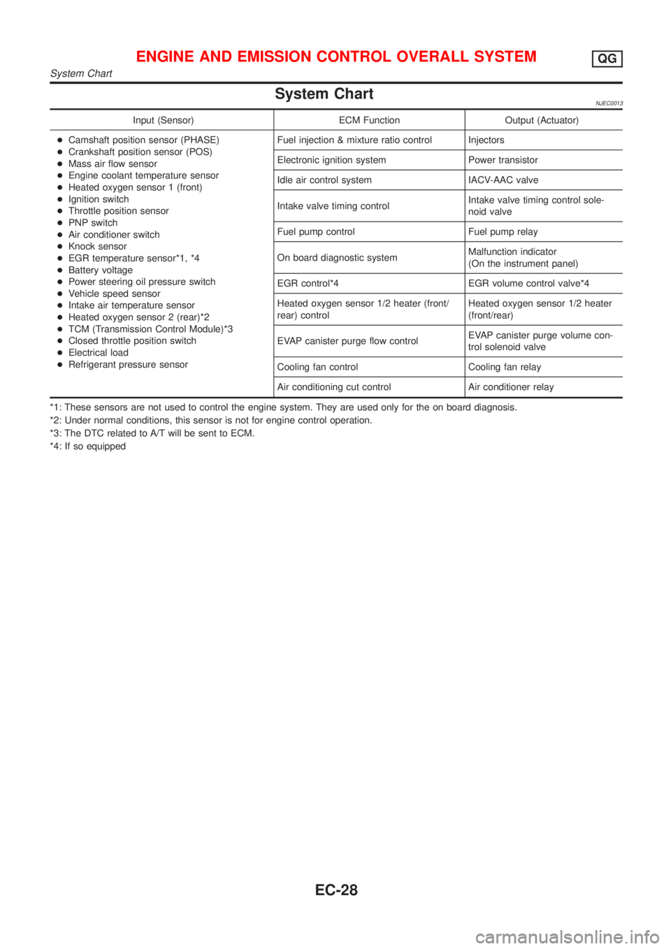
System ChartNJEC0013
Input (Sensor) ECM Function Output (Actuator)
+Camshaft position sensor (PHASE)
+Crankshaft position sensor (POS)
+Mass air flow sensor
+Engine coolant temperature sensor
+Heated oxygen sensor 1 (front)
+Ignition switch
+Throttle position sensor
+PNP switch
+Air conditioner switch
+Knock sensor
+EGR temperature sensor*1, *4
+Battery voltage
+Power steering oil pressure switch
+Vehicle speed sensor
+Intake air temperature sensor
+Heated oxygen sensor 2 (rear)*2
+TCM (Transmission Control Module)*3
+Closed throttle position switch
+Electrical load
+Refrigerant pressure sensorFuel injection & mixture ratio control Injectors
Electronic ignition system Power transistor
Idle air control system IACV-AAC valve
Intake valve timing controlIntake valve timing control sole-
noid valve
Fuel pump control Fuel pump relay
On board diagnostic systemMalfunction indicator
(On the instrument panel)
EGR control*4 EGR volume control valve*4
Heated oxygen sensor 1/2 heater (front/
rear) controlHeated oxygen sensor 1/2 heater
(front/rear)
EVAP canister purge flow controlEVAP canister purge volume con-
trol solenoid valve
Cooling fan control Cooling fan relay
Air conditioning cut control Air conditioner relay
*1: These sensors are not used to control the engine system. They are used only for the on board diagnosis.
*2: Under normal conditions, this sensor is not for engine control operation.
*3: The DTC related to A/T will be sent to ECM.
*4: If so equipped
ENGINE AND EMISSION CONTROL OVERALL SYSTEMQG
System Chart
EC-28
Page 325 of 2493
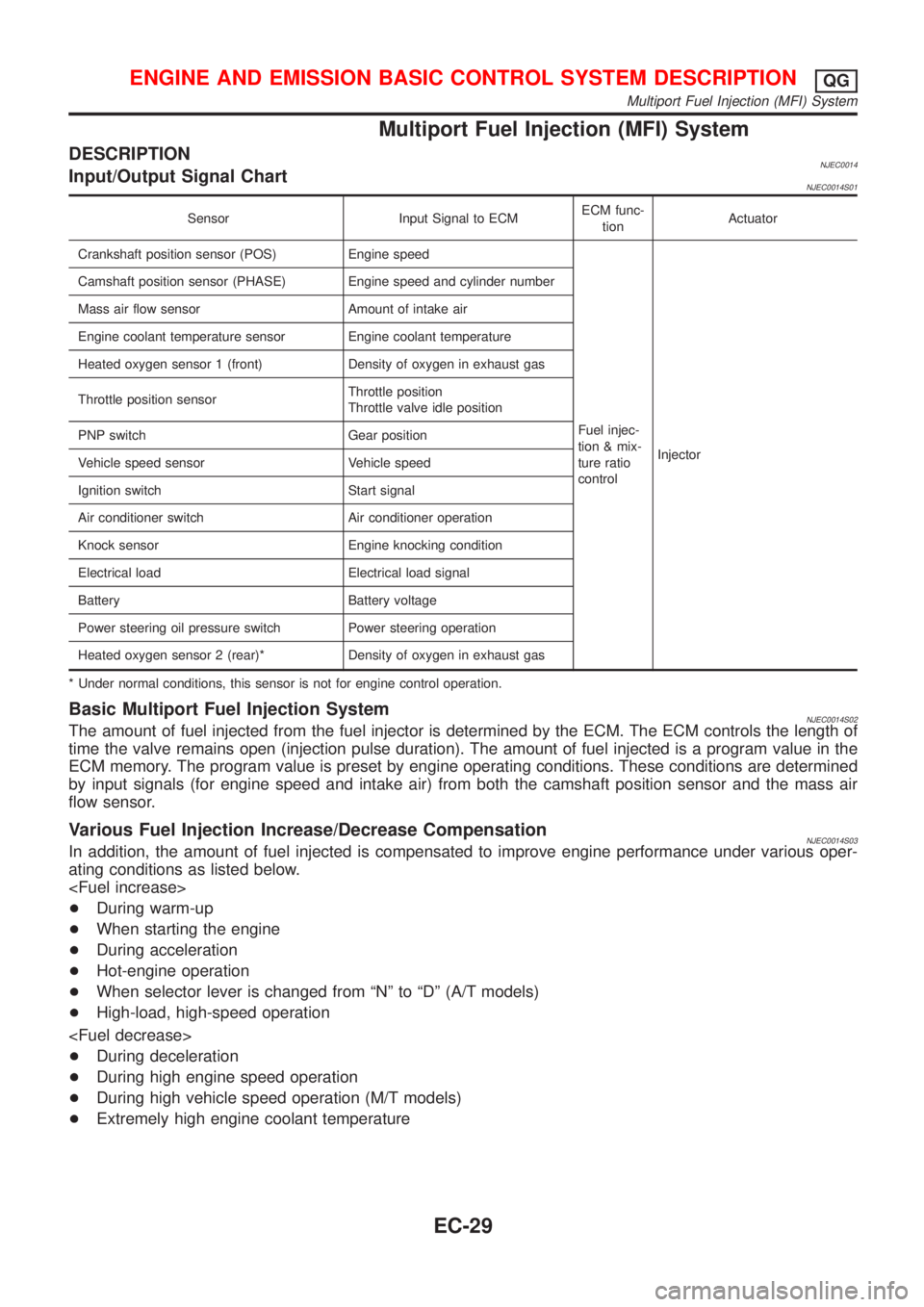
Multiport Fuel Injection (MFI) System
DESCRIPTIONNJEC0014Input/Output Signal ChartNJEC0014S01
Sensor Input Signal to ECMECM func-
tionActuator
Crankshaft position sensor (POS) Engine speed
Fuel injec-
tion & mix-
ture ratio
controlInjector Camshaft position sensor (PHASE) Engine speed and cylinder number
Mass air flow sensor Amount of intake air
Engine coolant temperature sensor Engine coolant temperature
Heated oxygen sensor 1 (front) Density of oxygen in exhaust gas
Throttle position sensorThrottle position
Throttle valve idle position
PNP switch Gear position
Vehicle speed sensor Vehicle speed
Ignition switch Start signal
Air conditioner switch Air conditioner operation
Knock sensor Engine knocking condition
Electrical load Electrical load signal
Battery Battery voltage
Power steering oil pressure switch Power steering operation
Heated oxygen sensor 2 (rear)* Density of oxygen in exhaust gas
* Under normal conditions, this sensor is not for engine control operation.
Basic Multiport Fuel Injection SystemNJEC0014S02The amount of fuel injected from the fuel injector is determined by the ECM. The ECM controls the length of
time the valve remains open (injection pulse duration). The amount of fuel injected is a program value in the
ECM memory. The program value is preset by engine operating conditions. These conditions are determined
by input signals (for engine speed and intake air) from both the camshaft position sensor and the mass air
flow sensor.
Various Fuel Injection Increase/Decrease CompensationNJEC0014S03In addition, the amount of fuel injected is compensated to improve engine performance under various oper-
ating conditions as listed below.
+During warm-up
+When starting the engine
+During acceleration
+Hot-engine operation
+When selector lever is changed from ªNº to ªDº (A/T models)
+High-load, high-speed operation
+During deceleration
+During high engine speed operation
+During high vehicle speed operation (M/T models)
+Extremely high engine coolant temperature
ENGINE AND EMISSION BASIC CONTROL SYSTEM DESCRIPTIONQG
Multiport Fuel Injection (MFI) System
EC-29
Page 326 of 2493
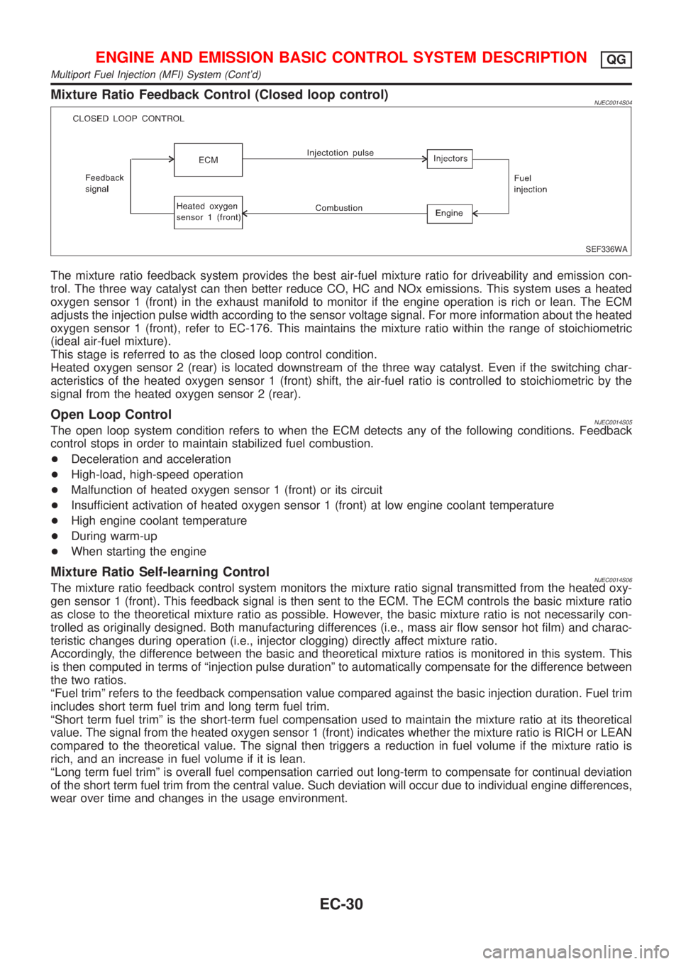
Mixture Ratio Feedback Control (Closed loop control)NJEC0014S04
SEF336WA
The mixture ratio feedback system provides the best air-fuel mixture ratio for driveability and emission con-
trol. The three way catalyst can then better reduce CO, HC and NOx emissions. This system uses a heated
oxygen sensor 1 (front) in the exhaust manifold to monitor if the engine operation is rich or lean. The ECM
adjusts the injection pulse width according to the sensor voltage signal. For more information about the heated
oxygen sensor 1 (front), refer to EC-176. This maintains the mixture ratio within the range of stoichiometric
(ideal air-fuel mixture).
This stage is referred to as the closed loop control condition.
Heated oxygen sensor 2 (rear) is located downstream of the three way catalyst. Even if the switching char-
acteristics of the heated oxygen sensor 1 (front) shift, the air-fuel ratio is controlled to stoichiometric by the
signal from the heated oxygen sensor 2 (rear).
Open Loop ControlNJEC0014S05The open loop system condition refers to when the ECM detects any of the following conditions. Feedback
control stops in order to maintain stabilized fuel combustion.
+Deceleration and acceleration
+High-load, high-speed operation
+Malfunction of heated oxygen sensor 1 (front) or its circuit
+Insufficient activation of heated oxygen sensor 1 (front) at low engine coolant temperature
+High engine coolant temperature
+During warm-up
+When starting the engine
Mixture Ratio Self-learning ControlNJEC0014S06The mixture ratio feedback control system monitors the mixture ratio signal transmitted from the heated oxy-
gen sensor 1 (front). This feedback signal is then sent to the ECM. The ECM controls the basic mixture ratio
as close to the theoretical mixture ratio as possible. However, the basic mixture ratio is not necessarily con-
trolled as originally designed. Both manufacturing differences (i.e., mass air flow sensor hot film) and charac-
teristic changes during operation (i.e., injector clogging) directly affect mixture ratio.
Accordingly, the difference between the basic and theoretical mixture ratios is monitored in this system. This
is then computed in terms of ªinjection pulse durationº to automatically compensate for the difference between
the two ratios.
ªFuel trimº refers to the feedback compensation value compared against the basic injection duration. Fuel trim
includes short term fuel trim and long term fuel trim.
ªShort term fuel trimº is the short-term fuel compensation used to maintain the mixture ratio at its theoretical
value. The signal from the heated oxygen sensor 1 (front) indicates whether the mixture ratio is RICH or LEAN
compared to the theoretical value. The signal then triggers a reduction in fuel volume if the mixture ratio is
rich, and an increase in fuel volume if it is lean.
ªLong term fuel trimº is overall fuel compensation carried out long-term to compensate for continual deviation
of the short term fuel trim from the central value. Such deviation will occur due to individual engine differences,
wear over time and changes in the usage environment.
ENGINE AND EMISSION BASIC CONTROL SYSTEM DESCRIPTIONQG
Multiport Fuel Injection (MFI) System (Cont'd)
EC-30
Page 327 of 2493
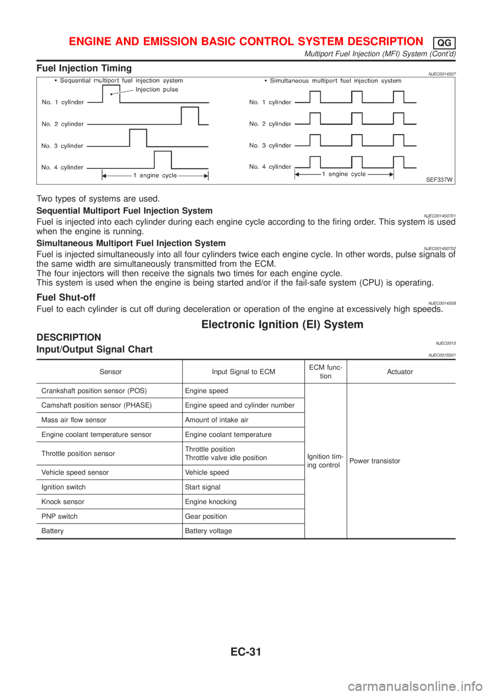
Fuel Injection TimingNJEC0014S07
SEF337W
Two types of systems are used.
Sequential Multiport Fuel Injection System
NJEC0014S0701Fuel is injected into each cylinder during each engine cycle according to the firing order. This system is used
when the engine is running.
Simultaneous Multiport Fuel Injection System
NJEC0014S0702Fuel is injected simultaneously into all four cylinders twice each engine cycle. In other words, pulse signals of
the same width are simultaneously transmitted from the ECM.
The four injectors will then receive the signals two times for each engine cycle.
This system is used when the engine is being started and/or if the fail-safe system (CPU) is operating.
Fuel Shut-offNJEC0014S08Fuel to each cylinder is cut off during deceleration or operation of the engine at excessively high speeds.
Electronic Ignition (EI) System
DESCRIPTIONNJEC0015Input/Output Signal ChartNJEC0015S01
Sensor Input Signal to ECMECM func-
tionActuator
Crankshaft position sensor (POS) Engine speed
Ignition tim-
ing controlPower transistor Camshaft position sensor (PHASE) Engine speed and cylinder number
Mass air flow sensor Amount of intake air
Engine coolant temperature sensor Engine coolant temperature
Throttle position sensorThrottle position
Throttle valve idle position
Vehicle speed sensor Vehicle speed
Ignition switch Start signal
Knock sensor Engine knocking
PNP switch Gear position
Battery Battery voltage
ENGINE AND EMISSION BASIC CONTROL SYSTEM DESCRIPTIONQG
Multiport Fuel Injection (MFI) System (Cont'd)
EC-31
Page 329 of 2493
+At high engine speeds.
+When the engine coolant temperature becomes excessively high.
+When operating power steering during low engine speed or low vehicle speed.
+When engine speed is excessively low.
+When the refrigerant pressure is excessively high or low.
Fuel Cut Control (at no load & high engine
speed)
DESCRIPTIONNJEC0017Input/Output Signal ChartNJEC0017S01
Sensor Input Signal to ECMECM func-
tionActuator
Vehicle speed sensor Vehicle speed
Fuel cut
controlInjectors PNP switch Neutral position
Throttle position sensor Throttle position
Engine coolant temperature sensor Engine coolant temperature
Crankshaft position sensor (POS) Engine speed
Camshaft position sensor (PHASE) Engine speed and cylinder number
If the engine speed is above 3,950 rpm with no load, (for example, in Neutral and engine speed over 4,000
rpm) fuel will be cut off after some time. The exact time when the fuel is cut off varies based on engine speed.
Fuel cut will operate until the engine speed reaches 1,150 rpm, then fuel cut is cancelled.
NOTE:
This function is different from deceleration control listed under ªMultiport Fuel Injection (MFI) Systemº,
EC-29.
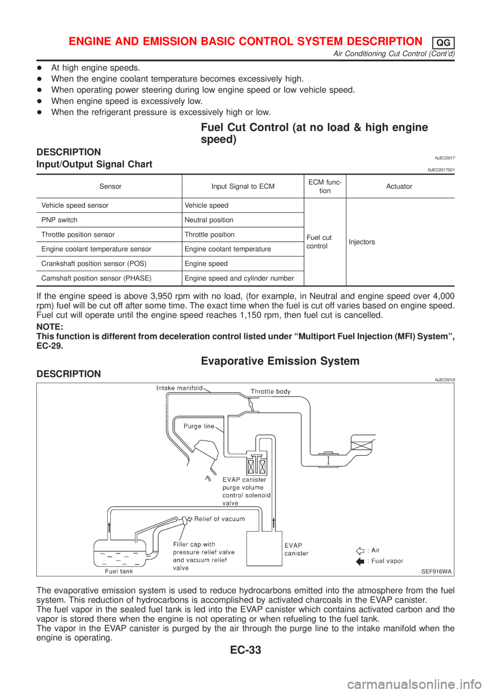
Evaporative Emission System
DESCRIPTIONNJEC0018
SEF916WA
The evaporative emission system is used to reduce hydrocarbons emitted into the atmosphere from the fuel
system. This reduction of hydrocarbons is accomplished by activated charcoals in the EVAP canister.
The fuel vapor in the sealed fuel tank is led into the EVAP canister which contains activated carbon and the
vapor is stored there when the engine is not operating or when refueling to the fuel tank.
The vapor in the EVAP canister is purged by the air through the purge line to the intake manifold when the
engine is operating.
ENGINE AND EMISSION BASIC CONTROL SYSTEM DESCRIPTIONQG
Air Conditioning Cut Control (Cont'd)
EC-33
Page 335 of 2493
If results are unsatisfactory, perform Fuel Pressure Regulator
Check, EC-39.
SEF718B
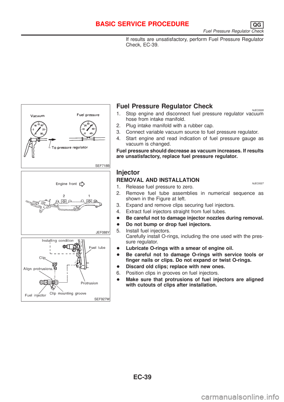
Fuel Pressure Regulator CheckNJEC00261. Stop engine and disconnect fuel pressure regulator vacuum
hose from intake manifold.
2. Plug intake manifold with a rubber cap.
3. Connect variable vacuum source to fuel pressure regulator.
4. Start engine and read indication of fuel pressure gauge as
vacuum is changed.
Fuel pressure should decrease as vacuum increases. If results
are unsatisfactory, replace fuel pressure regulator.
JEF088Y
SEF927W
Injector
REMOVAL AND INSTALLATIONNJEC00271. Release fuel pressure to zero.
2. Remove fuel tube assemblies in numerical sequence as
shown in the Figure at left.
3. Expand and remove clips securing fuel injectors.
4. Extract fuel injectors straight from fuel tubes.
+Be careful not to damage injector nozzles during removal.
+Do not bump or drop fuel injectors.
5. Install fuel injectors.
Carefully install O-rings, including the one used with the pres-
sure regulator.
+Lubricate O-rings with a smear of engine oil.
+Be careful not to damage O-rings with service tools or
finger nails or clips. Do not expand or twist O-rings.
+Discard old clips; replace with new ones.
6. Position clips in grooves on fuel injectors.
+Make sure that protrusions of fuel injectors are aligned
with cutouts of clips after installation.
BASIC SERVICE PROCEDUREQG
Fuel Pressure Regulator Check
EC-39
Page 336 of 2493
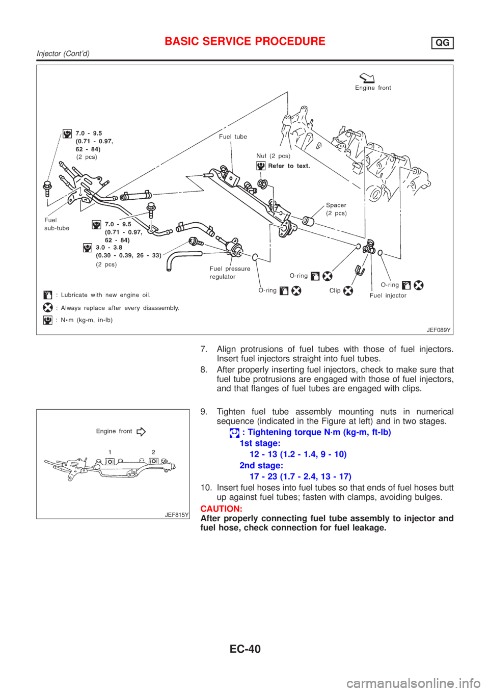
JEF089Y
7. Align protrusions of fuel tubes with those of fuel injectors.
Insert fuel injectors straight into fuel tubes.
8. After properly inserting fuel injectors, check to make sure that
fuel tube protrusions are engaged with those of fuel injectors,
and that flanges of fuel tubes are engaged with clips.
JEF815Y
9. Tighten fuel tube assembly mounting nuts in numerical
sequence (indicated in the Figure at left) and in two stages.
: Tightening torque N´m (kg-m, ft-lb)
1st stage:
12 - 13 (1.2 - 1.4, 9 - 10)
2nd stage:
17 - 23 (1.7 - 2.4, 13 - 17)
10. Insert fuel hoses into fuel tubes so that ends of fuel hoses butt
up against fuel tubes; fasten with clamps, avoiding bulges.
CAUTION:
After properly connecting fuel tube assembly to injector and
fuel hose, check connection for fuel leakage.
BASIC SERVICE PROCEDUREQG
Injector (Cont'd)
EC-40