heating NISSAN ALMERA N16 2001 Electronic Repair Manual
[x] Cancel search | Manufacturer: NISSAN, Model Year: 2001, Model line: ALMERA N16, Model: NISSAN ALMERA N16 2001Pages: 2493, PDF Size: 66.97 MB
Page 10 of 2493
+Do not use gasoline, kerosine, diesel fuel, gas oil, thinners or
solvents for cleaning skin.
+If skin disorders develop, obtain medical advice without delay.
+Where practicable, degrease components prior to handling.
+Where there is a risk of eye contact, eye protection should be
worn, for example, chemical goggles or face shields; in addi-
tion an eye wash facility should be provided.
Environmental Protection PrecautionsNJGI0001S0702Burning used engine oil in small space heaters or boilers can be
recommended only for units of approved design. The heating sys-
tem must meet the requirements of HM Inspectorate of Pollution for
small burners of less than 0.4 MW. If in doubt, check with the
appropriate local authority and/or manufacturer of the approved
appliance.
Dispose of used oil and used oil filters through authorized waste
disposal contractors to licensed waste disposal sites, or to the
waste oil reclamation trade. If in doubt, contact the local authority
for advice on disposal facilities.
It is illegal to pour used oil on to the ground, down sewers or drains,
or into water courses.
The regulations concerning the pollution vary between
regions.
PRECAUTIONS FOR FUELNJGI0001S08Gasoline EngineNJGI0001S0803Europe
Models with three way catalyst
Unleaded premium gasoline of at least 95 octane (RON)
If premium gasoline is not available, unleaded regular gaso-
line with an octane rating of 91 (RON) may be temporarily
used, but only under the following precautions:
+Have the fuel tank filled only partially with unleaded regu-
lar gasoline, and fill up with premium unleaded gasoline
as soon as possible.
+Avoid full throttle driving and abrupt acceleration.
CAUTION:
Do not use leaded gasoline. Using leaded gasoline will dam-
age the three way catalyst.
Except For Europe
Models without three way catalyst
Leaded gasoline of at least 91 octane (RON)
Models with three way catalyst
Unleaded gasoline of above 91 octane (RON)
For improved vehicle performance, Nissan recommends the use of
premium unleaded gasoline above 95 octane (RON).
CAUTION:
Do not use leaded gasoline. Using leaded gasoline will dam-
age the three way catalyst.
Diesel Engine*:NJGI0001S0804Diesel fuel of at least 50 cetane
* If two types of diesel fuel are available, use summer or winter
fuel properly according to the following temperature conditions.
+Above þ7ÉC (20ÉF) ... Summer type diesel fuel.
+Below þ7ÉC (20ÉF) ... Winter type diesel fuel.
CAUTION:
+Do not use home heating oil, gasoline, or other alternate
PRECAUTIONS
Precautions (Cont'd)
GI-8
Page 25 of 2493
Engine Compartment
There are several reasons a vehicle or engine vibration could
cause an electrical complaint. Some of the things to check for are:
+Connectors not fully seated.
+Wiring harness not long enough and is being stressed due to
engine vibrations or rocking.
+Wires laying across brackets or moving components.
+Loose, dirty or corroded ground wires.
+Wires routed too close to hot components.
To inspect components under the hood, start by verifying the integ-
rity of ground connections. (Refer to GROUND INSPECTION
described later.) First check that the system is properly grounded.
Then check for loose connection bygently shakingthe wiring or
components as previously explained. Using the wiring diagrams
inspect the wiring for continuity.
Behind The Instrument Panel
An improperly routed or improperly clamped harness can become
pinched during accessory installation. Vehicle vibration can aggra-
vate a harness which is routed along a bracket or near a screw.
Under Seating Areas
An unclamped or loose harness can cause wiring to be pinched by
seat components (such as slide guides) during vehicle vibration. If
the wiring runs under seating areas, inspect wire routing for pos-
sible damage or pinching.
SGI842
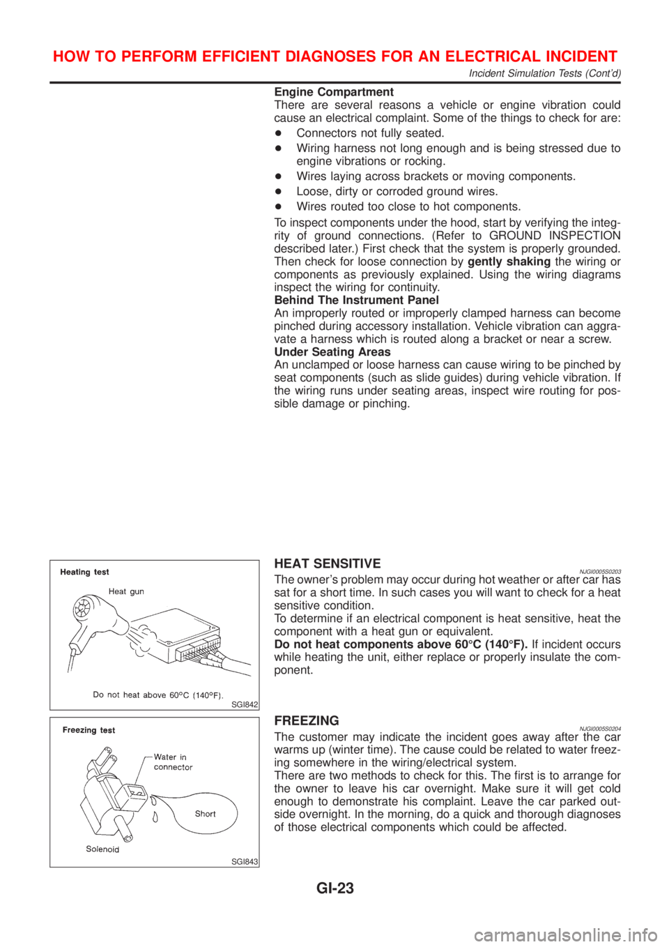
HEAT SENSITIVENJGI0005S0203The owner's problem may occur during hot weather or after car has
sat for a short time. In such cases you will want to check for a heat
sensitive condition.
To determine if an electrical component is heat sensitive, heat the
component with a heat gun or equivalent.
Do not heat components above 60ÉC (140ÉF).If incident occurs
while heating the unit, either replace or properly insulate the com-
ponent.
SGI843
FREEZINGNJGI0005S0204The customer may indicate the incident goes away after the car
warms up (winter time). The cause could be related to water freez-
ing somewhere in the wiring/electrical system.
There are two methods to check for this. The first is to arrange for
the owner to leave his car overnight. Make sure it will get cold
enough to demonstrate his complaint. Leave the car parked out-
side overnight. In the morning, do a quick and thorough diagnoses
of those electrical components which could be affected.
HOW TO PERFORM EFFICIENT DIAGNOSES FOR AN ELECTRICAL INCIDENT
Incident Simulation Tests (Cont'd)
GI-23
Page 249 of 2493
ENGINE LUBRICATION &
COOLING SYSTEMS
SECTION
LC
CONTENTS
QG
ENGINE LUBRICATION SYSTEM..................................3
Precautions ..................................................................3
LIQUID GASKET APPLICATION PROCEDURE............3
Preparation ..................................................................3
SPECIAL SERVICE TOOLS........................................3
Lubrication Circuit ........................................................4
Oil Pressure Check......................................................5
Oil Pump ......................................................................5
REMOVAL AND INSTALLATION.................................5
DISASSEMBLY AND ASSEMBLY................................6
INSPECTION.............................................................7
REGULATOR VALVE INSPECTION............................7
Changing Engine Oil....................................................8
Changing Oil Filter .......................................................9
Service Data and Specifications (SDS).....................10
OIL PRESSURE CHECK..........................................10
OIL PUMP INSPECTION..........................................10
REGULATOR VALVE INSPECTION..........................10
OIL CAPACITY........................................................10
ENGINE COOLING SYSTEM........................................ 11
Precautions ................................................................ 11
LIQUID GASKET APPLICATION PROCEDURE.......... 11
Preparation ................................................................ 11
SPECIAL SERVICE TOOLS...................................... 11
Cooling Circuit ...........................................................12
System Check............................................................12
CHECKING COOLING SYSTEM HOSES...................12
CHECKING RADIATOR............................................13
CHECKING RADIATOR CAP....................................13
CHECKING COOLING SYSTEM FOR LEAKS............13
Water Pump ...............................................................14
REMOVAL AND INSTALLATION...............................14
INSPECTION...........................................................14
Thermostat .................................................................15
REMOVAL AND INSTALLATION...............................15
INSPECTION...........................................................16
Radiator .....................................................................16
COMPONENTS.......................................................16
Cooling Fan ...............................................................17
COMPONENTS.......................................................17
CONTROL SYSTEM................................................17
Changing Engine Coolant..........................................17
- DRAINING ENGINE COOLANT -............................17
- REFILLING ENGINE COOLANT -...........................18
- FLUSHING COOLING SYSTEM -............................19
Radiator (Aluminum type) ..........................................20
PREPARATION.......................................................20
DISASSEMBLY........................................................20
ASSEMBLY.............................................................21
INSPECTION...........................................................22
Overheating Cause Analysis .....................................23
Service Data and Specifications (SDS).....................24
THERMOSTAT........................................................24
RADIATOR..............................................................24
COOLANT CAPACITY..............................................24
YD
ENGINE LUBRICATION SYSTEM................................25
Precautions ................................................................25
LIQUID GASKET APPLICATION PROCEDURE..........25
Preparation ................................................................25
SPECIAL SERVICE TOOLS......................................25
Lubrication Circuit ......................................................26
Oil Pressure Check....................................................27
Oil Pump ....................................................................27
REMOVAL AND INSTALLATION...............................27
DISASSEMBLY AND ASSEMBLY..............................28
OIL PUMP INSPECTION..........................................28
REGULATOR VALVE INSPECTION..........................29
Changing Engine Oil..................................................30
Oil Filter Bracket ........................................................31
REMOVAL AND INSTALLATION...............................31
Changing Oil Filter .....................................................31
REMOVAL...............................................................32
INSTALLATION........................................................32
Oil Cooler ...................................................................33
REMOVAL AND INSTALLATION...............................33
Service Data and Specifications (SDS).....................34
OIL PRESSURE CHECK..........................................34
Page 250 of 2493
REGULATOR VALVE INSPECTION..........................34
OIL PUMP INSPECTION..........................................34
ENGINE OIL CAPACITY...........................................34
ENGINE COOLING SYSTEM........................................35
Precautions ................................................................35
LIQUID GASKET APPLICATION PROCEDURE..........35
Preparation ................................................................35
SPECIAL SERVICE TOOLS......................................35
Cooling Circuit ...........................................................36
System Check............................................................37
CHECKING COOLING SYSTEM HOSES...................37
CHECKING RADIATOR............................................37
CHECKING RADIATOR CAP....................................37
CHECKING COOLING SYSTEM FOR LEAKS............38
Water Pump ...............................................................38
REMOVAL AND INSTALLATION...............................38
REMOVAL...............................................................39
INSPECTION...........................................................39
INSTALLATION........................................................39
Thermostat .................................................................40
REMOVAL AND INSTALLATION...............................40
INSPECTION...........................................................41
Radiator .....................................................................41
COMPONENTS.......................................................41
REMOVAL AND INSTALLATION...............................42
Cooling Fan ...............................................................42
COMPONENTS.......................................................42
CONTROL SYSTEM................................................42
Changing Engine Coolant..........................................43
- DRAINING ENGINE COOLANT -............................43
- REFILLING ENGINE COOLANT -...........................43
- FLUSHING COOLING SYSTEM -............................45
Radiator (Aluminum type) ..........................................46
Overheating Cause Analysis .....................................46
Service Data and Specifications (SDS).....................47
THERMOSTAT........................................................47
RADIATOR..............................................................47
ENGINE COOLANT CAPACITY................................47
CONTENTS(Cont'd)
LC-2
Page 271 of 2493
SLC934
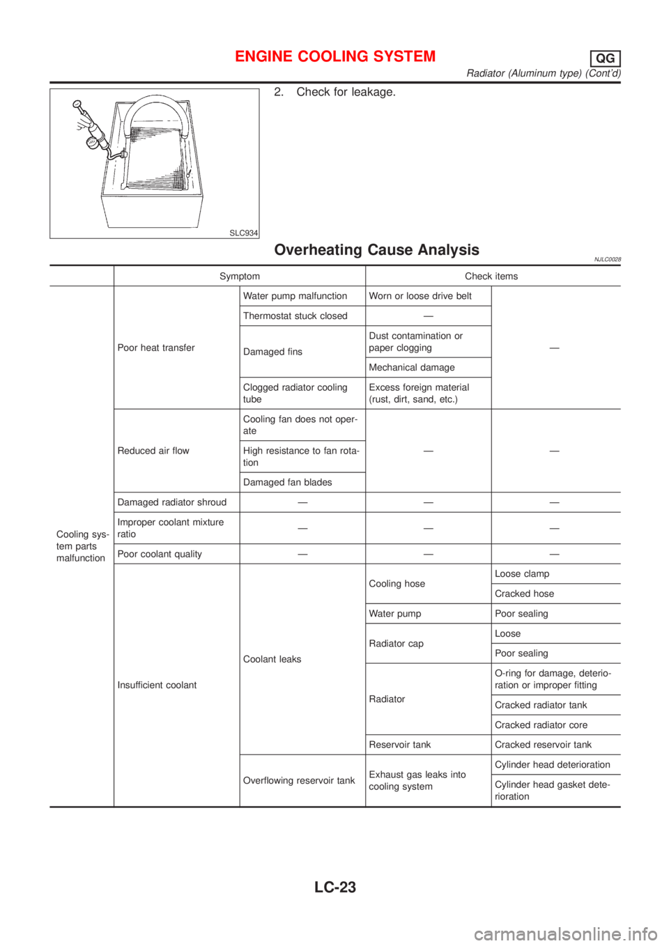
2. Check for leakage.
Overheating Cause AnalysisNJLC0028
Symptom Check items
Cooling sys-
tem parts
malfunctionPoor heat transferWater pump malfunction Worn or loose drive belt
Ð Thermostat stuck closed Ð
Damaged finsDust contamination or
paper clogging
Mechanical damage
Clogged radiator cooling
tubeExcess foreign material
(rust, dirt, sand, etc.)
Reduced air flowCooling fan does not oper-
ate
ÐÐ High resistance to fan rota-
tion
Damaged fan blades
Damaged radiator shroud Ð Ð Ð
Improper coolant mixture
ratioÐÐÐ
Poor coolant quality Ð Ð Ð
Insufficient coolantCoolant leaksCooling hoseLoose clamp
Cracked hose
Water pump Poor sealing
Radiator capLoose
Poor sealing
RadiatorO-ring for damage, deterio-
ration or improper fitting
Cracked radiator tank
Cracked radiator core
Reservoir tank Cracked reservoir tank
Overflowing reservoir tankExhaust gas leaks into
cooling systemCylinder head deterioration
Cylinder head gasket dete-
rioration
ENGINE COOLING SYSTEMQG
Radiator (Aluminum type) (Cont'd)
LC-23
Page 272 of 2493
Symptom Check items
Except cool-
ing system
parts mal-
functionÐ Overload on engineAbusive drivingHigh engine rpm under no
load
Driving in low gear for
extended time
Driving at extremely high
speed
Powertrain system malfunc-
tion
Ð Installed improper size
wheels and tires
Dragging brakes
Improper ignition timing
Blocked or restricted air
flowBlocked bumper Ð
Ð Blocked radiator grilleInstalled car brassiere
Mud contamination or
paper clogging
Blocked radiator Ð
Blocked condenser
Ð
Installed large fog lamp
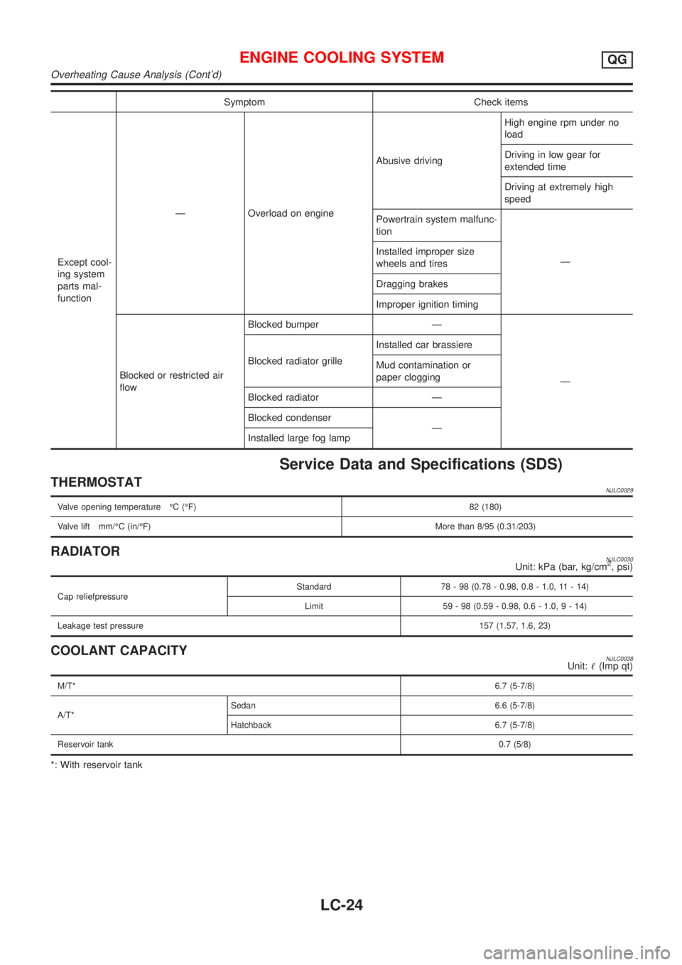
Service Data and Specifications (SDS)
THERMOSTATNJLC0029
Valve opening temperature ÉC (ÉF) 82 (180)
Valve lift mm/ÉC (in/ÉF)More than 8/95 (0.31/203)
RADIATORNJLC0030Unit: kPa (bar, kg/cm2, psi)
Cap reliefpressureStandard 78 - 98 (0.78 - 0.98, 0.8 - 1.0, 11 - 14)
Limit 59 - 98 (0.59 - 0.98, 0.6 - 1.0,9-14)
Leakage test pressure157 (1.57, 1.6, 23)
COOLANT CAPACITYNJLC0038Unit:!(Imp qt)
M/T*6.7 (5-7/8)
A/T*Sedan 6.6 (5-7/8)
Hatchback 6.7 (5-7/8)
Reservoir tank0.7 (5/8)
*: With reservoir tank
ENGINE COOLING SYSTEMQG
Overheating Cause Analysis (Cont'd)
LC-24
Page 294 of 2493
Radiator (Aluminum type)=NJLC0082Refer to LC-20, ªRadiator (Aluminum type)º.
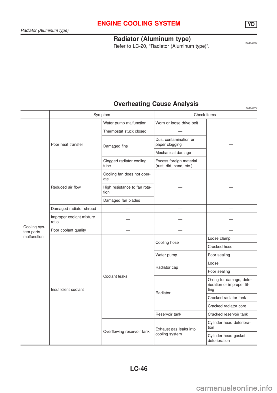
Overheating Cause AnalysisNJLC0070
Symptom Check items
Cooling sys-
tem parts
malfunctionPoor heat transferWater pump malfunction Worn or loose drive belt
Ð Thermostat stuck closed Ð
Damaged finsDust contamination or
paper clogging
Mechanical damage
Clogged radiator cooling
tubeExcess foreign material
(rust, dirt, sand, etc.)
Reduced air flowCooling fan does not oper-
ate
ÐÐ High resistance to fan rota-
tion
Damaged fan blades
Damaged radiator shroud Ð Ð Ð
Improper coolant mixture
ratioÐÐÐ
Poor coolant quality Ð Ð Ð
Insufficient coolantCoolant leaksCooling hoseLoose clamp
Cracked hose
Water pump Poor sealing
Radiator capLoose
Poor sealing
RadiatorO-ring for damage, dete-
rioration or improper fit-
ting
Cracked radiator tank
Cracked radiator core
Reservoir tank Cracked reservoir tank
Overflowing reservoir tankExhaust gas leaks into
cooling systemCylinder head deteriora-
tion
Cylinder head gasket
deterioration
ENGINE COOLING SYSTEMYD
Radiator (Aluminum type)
LC-46
Page 295 of 2493
Symptom Check items
Except cool-
ing system
parts mal-
functionÐ Overload on engineAbusive drivingHigh engine rpm under
no load
Driving in low gear for
extended time
Driving at extremely high
speed
Powertrain system malfunc-
tion
Ð Installed improper size
wheels and tires
Dragging brakes
Improper ignition timing
Blocked or restricted air
flowBlocked bumper Ð
Ð Blocked radiator grilleInstalled car brassiere
Mud contamination or
paper clogging
Blocked radiator Ð
Blocked condenser
Ð
Installed large fog lamp
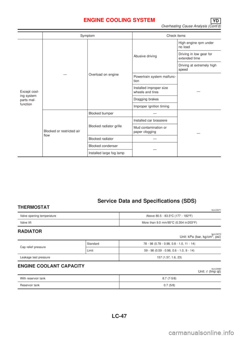
Service Data and Specifications (SDS)
THERMOSTATNJLC0071
Valve opening temperature Above 80.5 - 83.5ÉC (177 - 182ÉF)
Valve liftMore than 9.0 mm/95ÉC (0.354 in/203ÉF)
RADIATORNJLC0073Unit: kPa (bar, kg/cm2, psi)
Cap relief pressureStandard 78 - 98 (0.78 - 0.98, 0.8 - 1.0, 11 - 14)
Limit 59 - 98 (0.59 - 0.98, 0.6 - 1.0,9-14)
Leakage test pressure157 (1.57, 1.6, 23)
ENGINE COOLANT CAPACITYNJLC0080Unit:!(Imp qt)
With reservoir tank8.7 (7-5/8)
Reservoir tank0.7 (5/8)
ENGINE COOLING SYSTEMYD
Overheating Cause Analysis (Cont'd)
LC-47
Page 300 of 2493
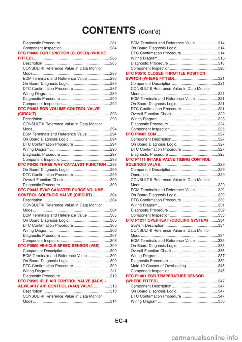
Diagnostic Procedure ..............................................281
Component Inspection .............................................284
DTC P0400 EGR FUNCTION (CLOSED) (WHERE
FITTED)........................................................................285
Description ...............................................................285
CONSULT-II Reference Value in Data Monitor
Mode ........................................................................286
ECM Terminals and Reference Value .....................286
On Board Diagnosis Logic.......................................286
DTC Confirmation Procedure ..................................287
Wiring Diagram ........................................................289
Diagnostic Procedure ..............................................290
Component Inspection .............................................292
DTC P0403 EGR VOLUME CONTROL VALVE
(CIRCUIT).....................................................................293
Description ...............................................................293
CONSULT-II Reference Value in Data Monitor
Mode ........................................................................294
ECM Terminals and Reference Value .....................294
On Board Diagnosis Logic.......................................294
DTC Confirmation Procedure ..................................294
Wiring Diagram ........................................................296
Diagnostic Procedure ..............................................297
Component Inspection .............................................298
DTC P0420 THREE WAY CATALYST FUNCTION...299
On Board Diagnosis Logic.......................................299
DTC Confirmation Procedure ..................................299
Overall Function Check ...........................................300
Diagnostic Procedure ..............................................300
DTC P0443 EVAP CANISTER PURGE VOLUME
CONTROL SOLENOID VALVE (CIRCUIT).................304
Description ...............................................................304
CONSULT-II Reference Value in Data Monitor
Mode ........................................................................304
ECM Terminals and Reference Value .....................305
On Board Diagnosis Logic.......................................305
DTC Confirmation Procedure ..................................305
Wiring Diagram ........................................................306
Diagnostic Procedure ..............................................307
Component Inspection .............................................308
DTC P0500 VEHICLE SPEED SENSOR (VSS).........309
Component Description ...........................................309
ECM Terminals and Reference Value .....................309
On Board Diagnosis Logic.......................................309
DTC Confirmation Procedure ..................................309
Wiring Diagram ........................................................ 311
Diagnostic Procedure ..............................................312
DTC P0505 IDLE AIR CONTROL VALVE (IACV) -
AUXILIARY AIR CONTROL (AAC) VALVE...............313
Description ...............................................................313
CONSULT-II Reference Value in Data Monitor
Mode ........................................................................314ECM Terminals and Reference Value .....................314
On Board Diagnosis Logic.......................................314
DTC Confirmation Procedure ..................................314
Wiring Diagram ........................................................315
Diagnostic Procedure ..............................................316
Component Inspection .............................................320
DTC P0510 CLOSED THROTTLE POSITION
SWITCH (WHERE FITTED).........................................321
Component Description ...........................................321
CONSULT-II Reference Value in Data Monitor
Mode ........................................................................321
ECM Terminals and Reference Value .....................321
On Board Diagnosis Logic.......................................321
DTC Confirmation Procedure ..................................321
Overall Function Check ...........................................322
Wiring Diagram ........................................................323
Diagnostic Procedure ..............................................324
Component Inspection .............................................325
DTC P0605 ECM.........................................................327
Component Description ...........................................327
On Board Diagnosis Logic.......................................327
DTC Confirmation Procedure ..................................327
Diagnostic Procedure ..............................................328
D T C P 1111INTAKE VALVE TIMING CONTROL
SOLENOID VALVE......................................................329
Component Description ...........................................329
Operation .................................................................329
CONSULT-II Reference Value in Data Monitor
Mode ........................................................................329
ECM Terminals and Reference Value .....................329
On Board Diagnosis Logic.......................................329
DTC Confirmation Procedure ..................................330
Wiring Diagram ........................................................331
Diagnostic Procedure ..............................................332
Component Inspection .............................................333
DTC P1217 OVERHEAT (COOLING SYSTEM).........334
System Description ..................................................334
CONSULT-II Reference Value in Data Monitor
Mode ........................................................................334
ECM Terminals and Reference Value .....................335
On Board Diagnosis Logic.......................................335
Overall Function Check ...........................................336
Wiring Diagram ........................................................337
Diagnostic Procedure ..............................................339
Main 12 Causes of Overheating..............................345
Component Inspection .............................................345
DTC P1401 EGR TEMPERATURE SENSOR
(WHERE FITTED)........................................................347
Component Description ...........................................347
On Board Diagnosis Logic.......................................347
DTC Confirmation Procedure ..................................347
Wiring Diagram ........................................................350
CONTENTS(Cont'd)
EC-4
Page 304 of 2493
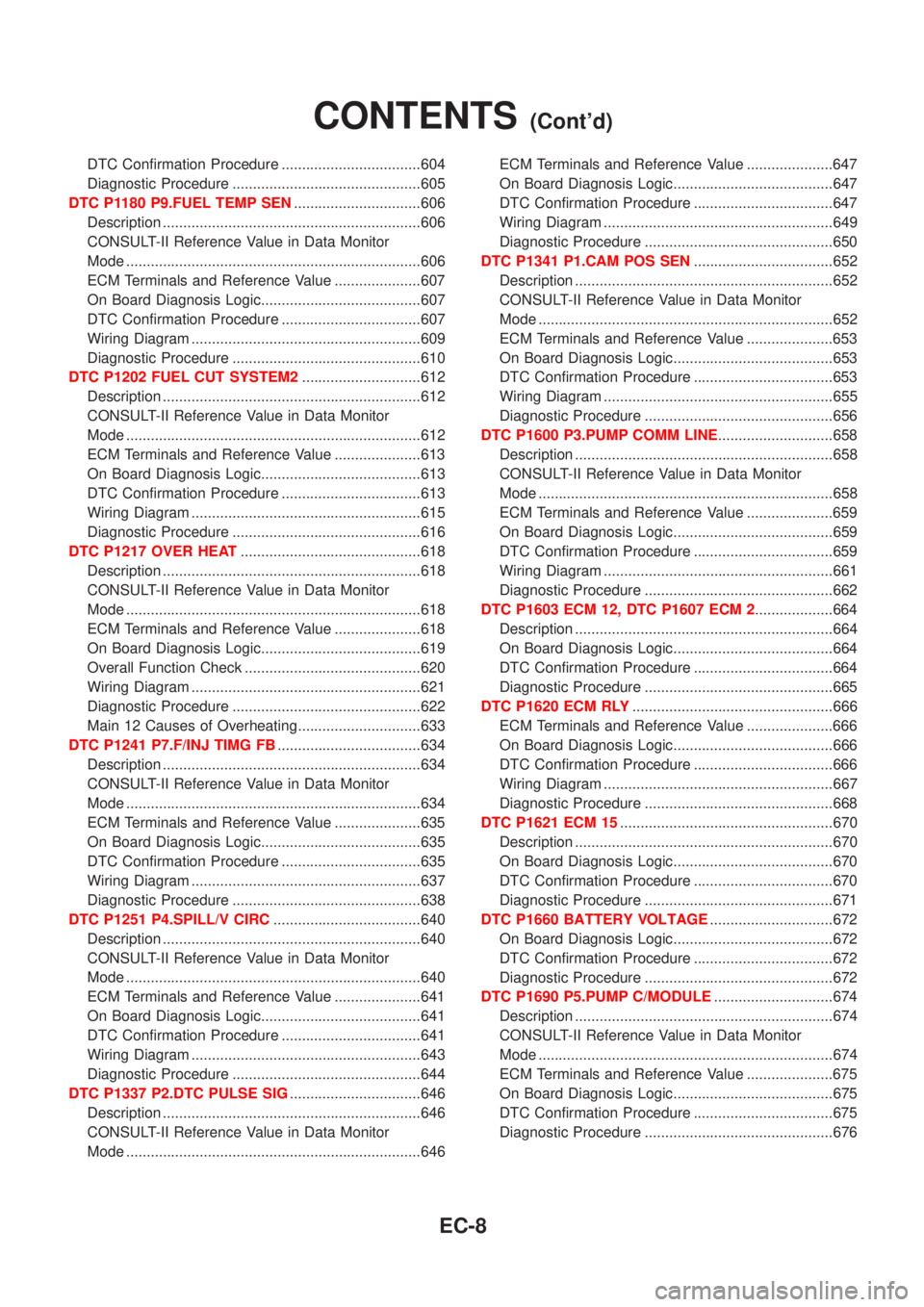
DTC Confirmation Procedure ..................................604
Diagnostic Procedure ..............................................605
DTC P1180 P9.FUEL TEMP SEN...............................606
Description ...............................................................606
CONSULT-II Reference Value in Data Monitor
Mode ........................................................................606
ECM Terminals and Reference Value .....................607
On Board Diagnosis Logic.......................................607
DTC Confirmation Procedure ..................................607
Wiring Diagram ........................................................609
Diagnostic Procedure ..............................................610
DTC P1202 FUEL CUT SYSTEM2.............................612
Description ...............................................................612
CONSULT-II Reference Value in Data Monitor
Mode ........................................................................612
ECM Terminals and Reference Value .....................613
On Board Diagnosis Logic.......................................613
DTC Confirmation Procedure ..................................613
Wiring Diagram ........................................................615
Diagnostic Procedure ..............................................616
DTC P1217 OVER HEAT............................................618
Description ...............................................................618
CONSULT-II Reference Value in Data Monitor
Mode ........................................................................618
ECM Terminals and Reference Value .....................618
On Board Diagnosis Logic.......................................619
Overall Function Check ...........................................620
Wiring Diagram ........................................................621
Diagnostic Procedure ..............................................622
Main 12 Causes of Overheating..............................633
DTC P1241 P7.F/INJ TIMG FB...................................634
Description ...............................................................634
CONSULT-II Reference Value in Data Monitor
Mode ........................................................................634
ECM Terminals and Reference Value .....................635
On Board Diagnosis Logic.......................................635
DTC Confirmation Procedure ..................................635
Wiring Diagram ........................................................637
Diagnostic Procedure ..............................................638
DTC P1251 P4.SPILL/V CIRC....................................640
Description ...............................................................640
CONSULT-II Reference Value in Data Monitor
Mode ........................................................................640
ECM Terminals and Reference Value .....................641
On Board Diagnosis Logic.......................................641
DTC Confirmation Procedure ..................................641
Wiring Diagram ........................................................643
Diagnostic Procedure ..............................................644
DTC P1337 P2.DTC PULSE SIG................................646
Description ...............................................................646
CONSULT-II Reference Value in Data Monitor
Mode ........................................................................646ECM Terminals and Reference Value .....................647
On Board Diagnosis Logic.......................................647
DTC Confirmation Procedure ..................................647
Wiring Diagram ........................................................649
Diagnostic Procedure ..............................................650
DTC P1341 P1.CAM POS SEN..................................652
Description ...............................................................652
CONSULT-II Reference Value in Data Monitor
Mode ........................................................................652
ECM Terminals and Reference Value .....................653
On Board Diagnosis Logic.......................................653
DTC Confirmation Procedure ..................................653
Wiring Diagram ........................................................655
Diagnostic Procedure ..............................................656
DTC P1600 P3.PUMP COMM LINE............................658
Description ...............................................................658
CONSULT-II Reference Value in Data Monitor
Mode ........................................................................658
ECM Terminals and Reference Value .....................659
On Board Diagnosis Logic.......................................659
DTC Confirmation Procedure ..................................659
Wiring Diagram ........................................................661
Diagnostic Procedure ..............................................662
DTC P1603 ECM 12, DTC P1607 ECM 2...................664
Description ...............................................................664
On Board Diagnosis Logic.......................................664
DTC Confirmation Procedure ..................................664
Diagnostic Procedure ..............................................665
DTC P1620 ECM RLY.................................................666
ECM Terminals and Reference Value .....................666
On Board Diagnosis Logic.......................................666
DTC Confirmation Procedure ..................................666
Wiring Diagram ........................................................667
Diagnostic Procedure ..............................................668
DTC P1621 ECM 15....................................................670
Description ...............................................................670
On Board Diagnosis Logic.......................................670
DTC Confirmation Procedure ..................................670
Diagnostic Procedure ..............................................671
DTC P1660 BATTERY VOLTAGE..............................672
On Board Diagnosis Logic.......................................672
DTC Confirmation Procedure ..................................672
Diagnostic Procedure ..............................................672
DTC P1690 P5.PUMP C/MODULE.............................674
Description ...............................................................674
CONSULT-II Reference Value in Data Monitor
Mode ........................................................................674
ECM Terminals and Reference Value .....................675
On Board Diagnosis Logic.......................................675
DTC Confirmation Procedure ..................................675
Diagnostic Procedure ..............................................676
CONTENTS(Cont'd)
EC-8