length NISSAN ALMERA N16 2001 Electronic Repair Manual
[x] Cancel search | Manufacturer: NISSAN, Model Year: 2001, Model line: ALMERA N16, Model: NISSAN ALMERA N16 2001Pages: 2493, PDF Size: 66.97 MB
Page 9 of 2493
SMA020D
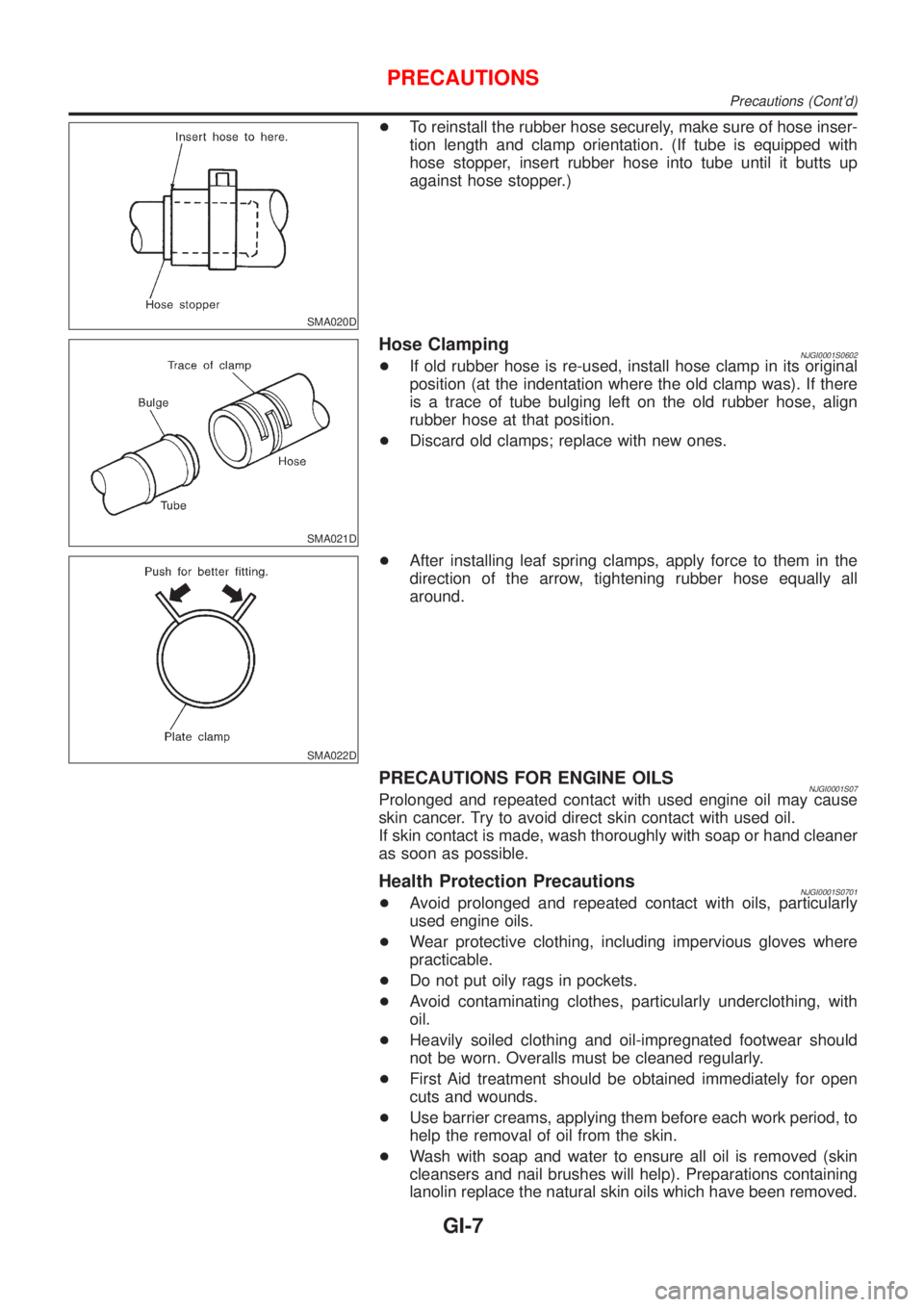
+To reinstall the rubber hose securely, make sure of hose inser-
tion length and clamp orientation. (If tube is equipped with
hose stopper, insert rubber hose into tube until it butts up
against hose stopper.)
SMA021D
Hose ClampingNJGI0001S0602+If old rubber hose is re-used, install hose clamp in its original
position (at the indentation where the old clamp was). If there
is a trace of tube bulging left on the old rubber hose, align
rubber hose at that position.
+Discard old clamps; replace with new ones.
SMA022D
+After installing leaf spring clamps, apply force to them in the
direction of the arrow, tightening rubber hose equally all
around.
PRECAUTIONS FOR ENGINE OILSNJGI0001S07Prolonged and repeated contact with used engine oil may cause
skin cancer. Try to avoid direct skin contact with used oil.
If skin contact is made, wash thoroughly with soap or hand cleaner
as soon as possible.
Health Protection PrecautionsNJGI0001S0701+Avoid prolonged and repeated contact with oils, particularly
used engine oils.
+Wear protective clothing, including impervious gloves where
practicable.
+Do not put oily rags in pockets.
+Avoid contaminating clothes, particularly underclothing, with
oil.
+Heavily soiled clothing and oil-impregnated footwear should
not be worn. Overalls must be cleaned regularly.
+First Aid treatment should be obtained immediately for open
cuts and wounds.
+Use barrier creams, applying them before each work period, to
help the removal of oil from the skin.
+Wash with soap and water to ensure all oil is removed (skin
cleansers and nail brushes will help). Preparations containing
lanolin replace the natural skin oils which have been removed.
PRECAUTIONS
Precautions (Cont'd)
GI-7
Page 45 of 2493
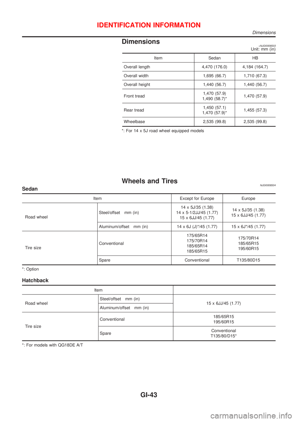
Dimensions=NJGI0008S03Unit: mm (in)
Item Sedan HB
Overall length 4,470 (176.0) 4,184 (164.7)
Overall width 1,695 (66.7) 1,710 (67.3)
Overall height 1,440 (56.7) 1,440 (56.7)
Front tread1,470 (57.9)
1,490 (58.7)*1,470 (57.9)
Rear tread1,450 (57.1)
1,470 (57.9)*1,455 (57.3)
Wheelbase 2,535 (99.8) 2,535 (99.8)
*: For 14 x 5J road wheel equipped models
Wheels and TiresNJGI0008S04Sedan
Item Except for Europe Europe
Road wheelSteel/offset mm (in)14 x 5J/35 (1.38)
14 x 5-1/2JJ/45 (1.77)
15 x 6JJ/45 (1.77)14 x 5J/35 (1.38)
15 x 6JJ/45 (1.77)
Aluminum/offset mm (in) 14 x 6J (J)*/45 (1.77) 15 x 6J*/45 (1.77)
Tire sizeConventional175/65R14
175/70R14
185/65R14
185/65R15175/70R14
185/65R15
195/60R15
Spare Conventional T135/80D15
*: Option
Hatchback
Item
Road wheelSteel/offset mm (in)
15 x 6JJ/45 (1.77)
Aluminum/offset mm (in)
Tire sizeConventional185/65R15
195/60R15
SpareConventional
T135/80/D15*
*: For models with QG18DE A/T
IDENTIFICATION INFORMATION
Dimensions
GI-43
Page 133 of 2493
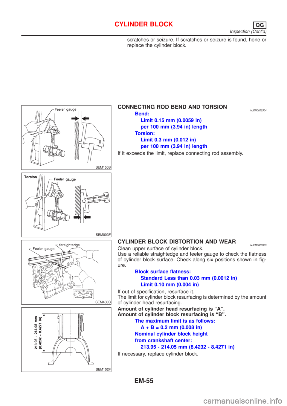
scratches or seizure. If scratches or seizure is found, hone or
replace the cylinder block.
SEM150B
CONNECTING ROD BEND AND TORSIONNJEM0026S04Bend:
Limit 0.15 mm (0.0059 in)
per 100 mm (3.94 in) length
Torsion:
Limit 0.3 mm (0.012 in)
per 100 mm (3.94 in) length
If it exceeds the limit, replace connecting rod assembly.
SEM003F
SEM486C
CYLINDER BLOCK DISTORTION AND WEARNJEM0026S05Clean upper surface of cylinder block.
Use a reliable straightedge and feeler gauge to check the flatness
of cylinder block surface. Check along six positions shown in fig-
ure.
Block surface flatness:
Standard Less than 0.03 mm (0.0012 in)
Limit 0.10 mm (0.004 in)
If out of specification, resurface it.
The limit for cylinder block resurfacing is determined by the amount
of cylinder head resurfacing.
SEM102F
Amount of cylinder head resurfacing is ªAº.
Amount of cylinder block resurfacing is ªBº.
The maximum limit is as follows:
A + B = 0.2 mm (0.008 in)
Nominal cylinder block height
from crankshaft center:
213.95 - 214.05 mm (8.4232 - 8.4271 in)
If necessary, replace cylinder block.
CYLINDER BLOCKQG
Inspection (Cont'd)
EM-55
Page 144 of 2493
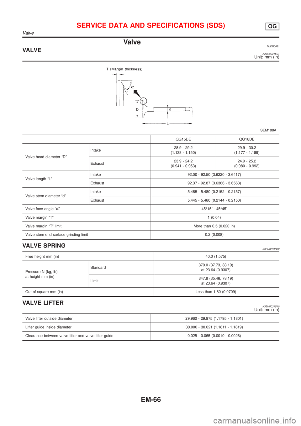
ValveNJEM0031VALVENJEM0031S01Unit: mm (in)
SEM188A
QG15DE QG18DE
Valve head diameter ªDºIntake28.9 - 29.2
(1.138 - 1.150)29.9 - 30.2
(1.177 - 1.189)
Exhaust23.9 - 24.2
(0.941 - 0.953)24.9 - 25.2
(0.980 - 0.992)
Valve length ªLºIntake 92.00 - 92.50 (3.6220 - 3.6417)
Exhaust 92.37 - 92.87 (3.6366 - 3.6563)
Valve stem diameter ªdºIntake 5.465 - 5.480 (0.2152 - 0.2157)
Exhaust 5.445 - 5.460 (0.2144 - 0.2150)
Valve face angle ªaº45É15¢- 45É45¢
Valve margin ªTº1 (0.04)
Valve margin ªTº limitMore than 0.5 (0.020 in)
Valve stem end surface grinding limit 0.2 (0.008)
VALVE SPRINGNJEM0031S02
Free height mm (in)40.0 (1.575)
Pressure N (kg, lb)
at height mm (in)Standard370.0 (37.73, 83.19)
at 23.64 (0.9307)
Limit347.8 (35.46, 78.19)
at 23.64 (0.9307)
Out-of-square mm (in)Less than 1.80 (0.0709)
VALVE LIFTERNJEM0031S10Unit: mm (in)
Valve lifter outside diameter 29.960 - 29.975 (1.1795 - 1.1801)
Lifter guide inside diameter 30.000 - 30.021 (1.1811 - 1.1819)
Clearance between valve lifter and valve lifter guide 0.025 - 0.065 (0.0010 - 0.0026)
SERVICE DATA AND SPECIFICATIONS (SDS)QG
Valve
EM-66
Page 145 of 2493
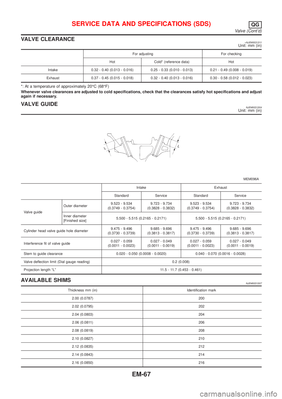
VALVE CLEARANCE=NJEM0031S11Unit: mm (in)
For adjusting For checking
Hot Cold* (reference data) Hot
Intake 0.32 - 0.40 (0.013 - 0.016) 0.25 - 0.33 (0.010 - 0.013) 0.21 - 0.49 (0.008 - 0.019)
Exhaust 0.37 - 0.45 (0.015 - 0.018) 0.32 - 0.40 (0.013 - 0.016) 0.30 - 0.58 (0.012 - 0.023)
*: At a temperature of approximately 20ÉC (68ÉF)
Whenever valve clearances are adjusted to cold specifications, check that the clearances satisfy hot specifications and adjust
again if necessary.
VALVE GUIDENJEM0031S04Unit: mm (in)
MEM096A
Intake Exhaust
Standard Service Standard Service
Valve guideOuter diameter9.523 - 9.534
(0.3749 - 0.3754)9.723 - 9.734
(0.3828 - 0.3832)9.523 - 9.534
(0.3749 - 0.3754)9.723 - 9.734
(0.3828 - 0.3832)
Inner diameter
[Finished size]5.500 - 5.515 (0.2165 - 0.2171) 5.500 - 5.515 (0.2165 - 0.2171)
Cylinder head valve guide hole diameter9.475 - 9.496
(0.3730 - 0.3739)9.685 - 9.696
(0.3813 - 0.3817)9.475 - 9.496
(0.3730 - 0.3739)9.685 - 9.696
(0.3813 - 0.3817)
Interference fit of valve guide0.027 - 0.059
(0.0011 - 0.0023)0.027 - 0.049
(0.0011 - 0.0019)0.027 - 0.059
(0.0011 - 0.0023)0.027 - 0.049
(0.0011 - 0.0019)
Stem to guide clearance 0.020 - 0.050 (0.0008 - 0.0020) 0.040 - 0.070 (0.0016 - 0.0028)
Valve deflection limit (Dial gauge reading) 0.2 (0.008)
Projection length ªLº 11.5 - 11.7 (0.453 - 0.461)
AVAILABLE SHIMSNJEM0031S07
Thickness mm (in) Identification mark
2.00 (0.0787) 200
2.02 (0.0795) 202
2.04 (0.0803) 204
2.06 (0.0811) 206
2.08 (0.0819) 208
2.10 (0.0827) 210
2.12 (0.0835) 212
2.14 (0.0843) 214
2.16 (0.0850) 216
SERVICE DATA AND SPECIFICATIONS (SDS)QG
Valve (Cont'd)
EM-67
Page 169 of 2493
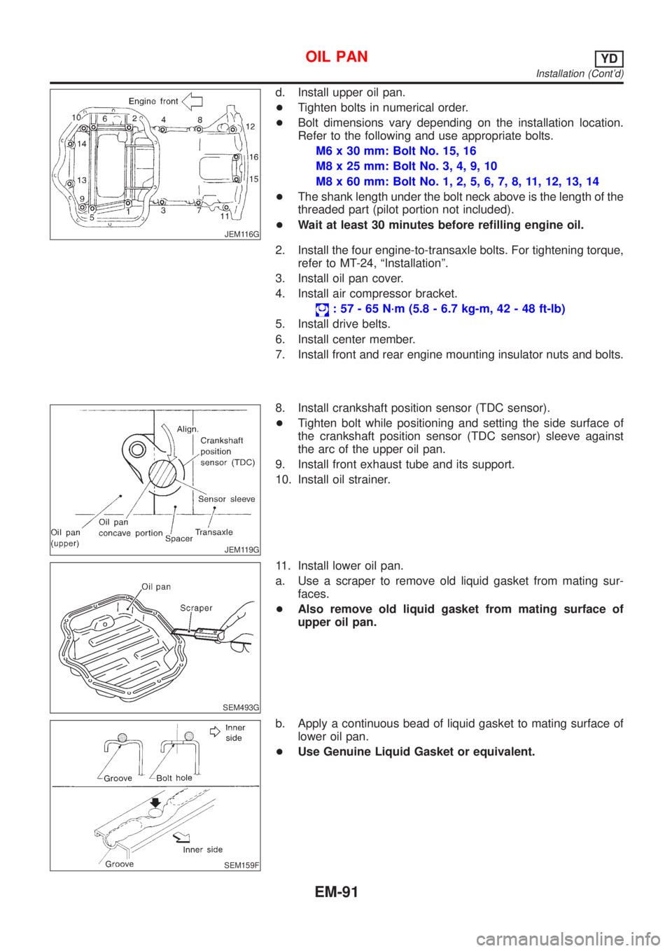
JEM116G
d. Install upper oil pan.
+Tighten bolts in numerical order.
+Bolt dimensions vary depending on the installation location.
Refer to the following and use appropriate bolts.
M6 x 30 mm: Bolt No. 15, 16
M8 x 25 mm: Bolt No. 3, 4, 9, 10
M8 x 60 mm: Bolt No. 1, 2, 5, 6, 7, 8, 11, 12, 13, 14
+The shank length under the bolt neck above is the length of the
threaded part (pilot portion not included).
+Wait at least 30 minutes before refilling engine oil.
2. Install the four engine-to-transaxle bolts. For tightening torque,
refer to MT-24, ªInstallationº.
3. Install oil pan cover.
4. Install air compressor bracket.
: 57 - 65 N´m (5.8 - 6.7 kg-m, 42 - 48 ft-lb)
5. Install drive belts.
6. Install center member.
7. Install front and rear engine mounting insulator nuts and bolts.
JEM119G
8. Install crankshaft position sensor (TDC sensor).
+Tighten bolt while positioning and setting the side surface of
the crankshaft position sensor (TDC sensor) sleeve against
the arc of the upper oil pan.
9. Install front exhaust tube and its support.
10. Install oil strainer.
SEM493G
11. Install lower oil pan.
a. Use a scraper to remove old liquid gasket from mating sur-
faces.
+Also remove old liquid gasket from mating surface of
upper oil pan.
SEM159F
b. Apply a continuous bead of liquid gasket to mating surface of
lower oil pan.
+Use Genuine Liquid Gasket or equivalent.
OIL PANYD
Installation (Cont'd)
EM-91
Page 177 of 2493
REMOVALNJEM0094S011. Remove engine and transaxle assembly. Refer to EM-136,
ªENGINE ASSEMBLYº.
2. Remove transaxle from engine. Place engine onto engine
stand (SST). Refer to EM-140, ªCYLINDER BLOCKº, ªDisas-
semblyº.
3. Remove the following parts:
+Oil pan (upper and lower)
Refer to EM-88, ªOIL PANº.
+Oil filter bracket
Refer to LC-31, ªOil Filter Bracketº.
+Injection tube
Refer to EC-509, ªInjection Tube and Injection Nozzleº.
4. Remove secondary timing chain and associated parts.
Refer to EM-93, ªSecondary Timing Chainº.
5. When removing rear chain case, remove camshaft sprockets.
Refer to EM-119, ªCAMSHAFTº.
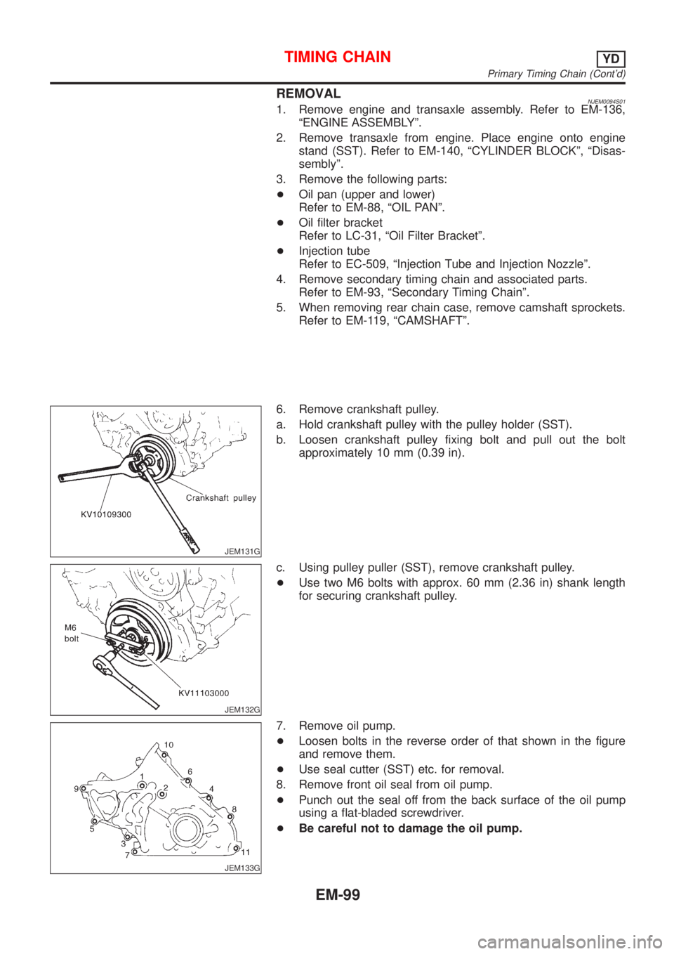
JEM131G
6. Remove crankshaft pulley.
a. Hold crankshaft pulley with the pulley holder (SST).
b. Loosen crankshaft pulley fixing bolt and pull out the bolt
approximately 10 mm (0.39 in).
JEM132G
c. Using pulley puller (SST), remove crankshaft pulley.
+Use two M6 bolts with approx. 60 mm (2.36 in) shank length
for securing crankshaft pulley.
JEM133G
7. Remove oil pump.
+Loosen bolts in the reverse order of that shown in the figure
and remove them.
+Use seal cutter (SST) etc. for removal.
8. Remove front oil seal from oil pump.
+Punch out the seal off from the back surface of the oil pump
using a flat-bladed screwdriver.
+Be careful not to damage the oil pump.
TIMING CHAINYD
Primary Timing Chain (Cont'd)
EM-99
Page 180 of 2493
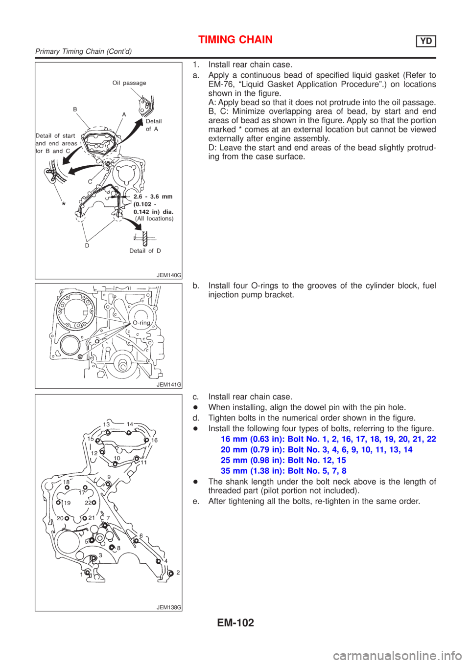
JEM140G
1. Install rear chain case.
a. Apply a continuous bead of specified liquid gasket (Refer to
EM-76, ªLiquid Gasket Application Procedureº.) on locations
shown in the figure.
A: Apply bead so that it does not protrude into the oil passage.
B, C: Minimize overlapping area of bead, by start and end
areas of bead as shown in the figure. Apply so that the portion
marked * comes at an external location but cannot be viewed
externally after engine assembly.
D: Leave the start and end areas of the bead slightly protrud-
ing from the case surface.
JEM141G
b. Install four O-rings to the grooves of the cylinder block, fuel
injection pump bracket.
JEM138G
c. Install rear chain case.
+When installing, align the dowel pin with the pin hole.
d. Tighten bolts in the numerical order shown in the figure.
+Install the following four types of bolts, referring to the figure.
16 mm (0.63 in): Bolt No. 1, 2, 16, 17, 18, 19, 20, 21, 22
20 mm (0.79 in): Bolt No. 3, 4, 6, 9, 10, 11, 13, 14
25 mm (0.98 in): Bolt No. 12, 15
35 mm (1.38 in): Bolt No. 5, 7, 8
+The shank length under the bolt neck above is the length of
threaded part (pilot portion not included).
e. After tightening all the bolts, re-tighten in the same order.
TIMING CHAINYD
Primary Timing Chain (Cont'd)
EM-102
Page 223 of 2493
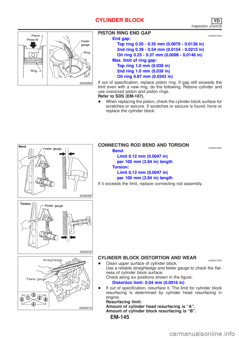
SEM599A
PISTON RING END GAPNJEM0073S03End gap:
Top ring 0.20 - 0.35 mm (0.0079 - 0.0138 in)
2nd ring 0.39 - 0.54 mm (0.0154 - 0.0213 in)
Oil ring 0.25 - 0.37 mm (0.0098 - 0.0146 in)
Max. limit of ring gap:
Top ring 1.0 mm (0.039 in)
2nd ring 1.0 mm (0.039 in)
Oil ring 0.87 mm (0.0343 in)
If out of specification, replace piston ring. If gap still exceeds the
limit even with a new ring, do the following. Rebore cylinder and
use oversized piston and piston rings.
Refer to SDS (EM-167).
+When replacing the piston, check the cylinder block surface for
scratches or seizure. If scratches or seizure is found, hone or
replace the cylinder block.
SEM038F
SEM003F
CONNECTING ROD BEND AND TORSIONNJEM0073S04Bend:
Limit 0.12 mm (0.0047 in)
per 100 mm (3.94 in) length
Torsion:
Limit 0.12 mm (0.0047 in)
per 100 mm (3.94 in) length
If it exceeds the limit, replace connecting rod assembly.
SEM501G
CYLINDER BLOCK DISTORTION AND WEARNJEM0073S05+Clean upper surface of cylinder block.
Use a reliable straightedge and feeler gauge to check the flat-
ness of cylinder block surface.
Check along six positions shown in the figure.
Distortion limit: 0.04 mm (0.0016 in)
+If out of specification, resurface it. The limit for cylinder block
resurfacing is determined by cylinder head resurfacing in
engine.
Resurfacing limit:
Amount of cylinder head resurfacing is ªAº.
Amount of cylinder block resurfacing is ªBº.
CYLINDER BLOCKYD
Inspection (Cont'd)
EM-145
Page 238 of 2493
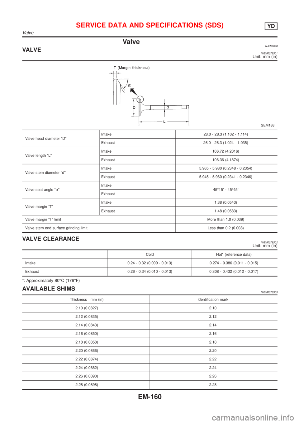
ValveNJEM0078VALVENJEM0078S01Unit: mm (in)
SEM188
Valve head diameter ªDºIntake 28.0 - 28.3 (1.102 - 1.114)
Exhaust 26.0 - 26.3 (1.024 - 1.035)
Valve length ªLºIntake 106.72 (4.2016)
Exhaust 106.36 (4.1874)
Valve stem diameter ªdºIntake 5.965 - 5.980 (0.2348 - 0.2354)
Exhaust 5.945 - 5.960 (0.2341 - 0.2346)
Valve seat angle ªaºIntake
45É15¢- 45É45¢
Exhaust
Valve margin ªTºIntake 1.38 (0.0543)
Exhaust 1.48 (0.0583)
Valve margin ªTº limitMore than 1.0 (0.039)
Valve stem end surface grinding limit Less than 0.2 (0.008)
VALVE CLEARANCENJEM0078S02Unit: mm (in)
Cold Hot* (reference data)
Intake 0.24 - 0.32 (0.009 - 0.013) 0.274 - 0.386 (0.011 - 0.015)
Exhaust 0.26 - 0.34 (0.010 - 0.013) 0.308 - 0.432 (0.012 - 0.017)
*: Approximately 80ÉC (176ÉF)
AVAILABLE SHIMSNJEM0078S03
Thickness mm (in) Identification mark
2.10 (0.0827) 2.10
2.12 (0.0835) 2.12
2.14 (0.0843) 2.14
2.16 (0.0850) 2.16
2.18 (0.0858) 2.18
2.20 (0.0866) 2.20
2.22 (0.0874) 2.22
2.24 (0.0882) 2.24
2.26 (0.0890) 2.26
2.28 (0.0898) 2.28
SERVICE DATA AND SPECIFICATIONS (SDS)YD
Valve
EM-160