warning NISSAN ALMERA N16 2001 Electronic Repair Manual
[x] Cancel search | Manufacturer: NISSAN, Model Year: 2001, Model line: ALMERA N16, Model: NISSAN ALMERA N16 2001Pages: 2493, PDF Size: 66.97 MB
Page 5 of 2493
PrecautionsNJGI0001Observe the following precautions to ensure safe and proper
servicing. These precautions are not described in each indi-
vidual section.
SGI646
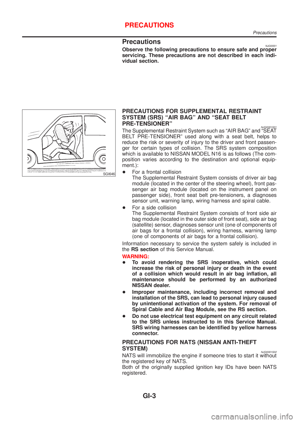
PRECAUTIONS FOR SUPPLEMENTAL RESTRAINT
SYSTEM (SRS) ªAIR BAGº AND ªSEAT BELT
PRE-TENSIONERº
NJGI0001S01The Supplemental Restraint System such as ªAIR BAGº and ªSEAT
BELT PRE-TENSIONERº used along with a seat belt, helps to
reduce the risk or severity of injury to the driver and front passen-
ger for certain types of collision. The SRS system composition
which is available to NISSAN MODEL N16 is as follows (The com-
position varies according to the destination and optional equip-
ment.):
+For a frontal collision
The Supplemental Restraint System consists of driver air bag
module (located in the center of the steering wheel), front pas-
senger air bag module (located on the instrument panel on
passenger side), front seat belt pre-tensioners, a diagnoses
sensor unit, warning lamp, wiring harness and spiral cable.
+For a side collision
The Supplemental Restraint System consists of front side air
bag module (located in the outer side of front seat), side air bag
(satellite) sensor, diagnoses sensor unit (one of components of
air bags for a frontal collision), wiring harness, warning lamp
(one of components of air bags for a frontal collision).
Information necessary to service the system safely is included in
theRS sectionof this Service Manual.
WARNING:
+To avoid rendering the SRS inoperative, which could
increase the risk of personal injury or death in the event
of a collision which would result in air bag inflation, all
maintenance should be performed by an authorized
NISSAN dealer.
+Improper maintenance, including incorrect removal and
installation of the SRS, can lead to personal injury caused
by unintentional activation of the system. For removal of
Spiral Cable and Air Bag Module, see the RS section.
+Do not use electrical test equipment on any circuit related
to the SRS unless instructed to in this Service Manual.
SRS wiring harnesses can be identified by yellow harness
connector.
PRECAUTIONS FOR NATS (NISSAN ANTI-THEFT
SYSTEM)
NJGI0001S02NATS will immobilize the engine if someone tries to start it without
the registered key of NATS.
Both of the originally supplied ignition key IDs have been NATS
registered.
PRECAUTIONS
Precautions
GI-3
Page 8 of 2493
Do not attempt to top off the fuel tank after the fuel pump nozzle
shuts off automatically. Continued refueling may cause fuel
overflow, resulting in fuel spray and possibly a fire.
WARNING:
To prevent ECM from storing the diagnostic trouble codes, do
not carelessly disconnect the harness connectors which are
related to the engine control system and TCM (Transmission
Control Module) system. The connectors should be discon-
nected only when working according to the WORK FLOW of
TROUBLE DIAGNOSES in EC and AT sections.
SGI787
PRECAUTIONS FOR MULTIPORT FUEL INJECTION
SYSTEM OR ENGINE CONTROL SYSTEM
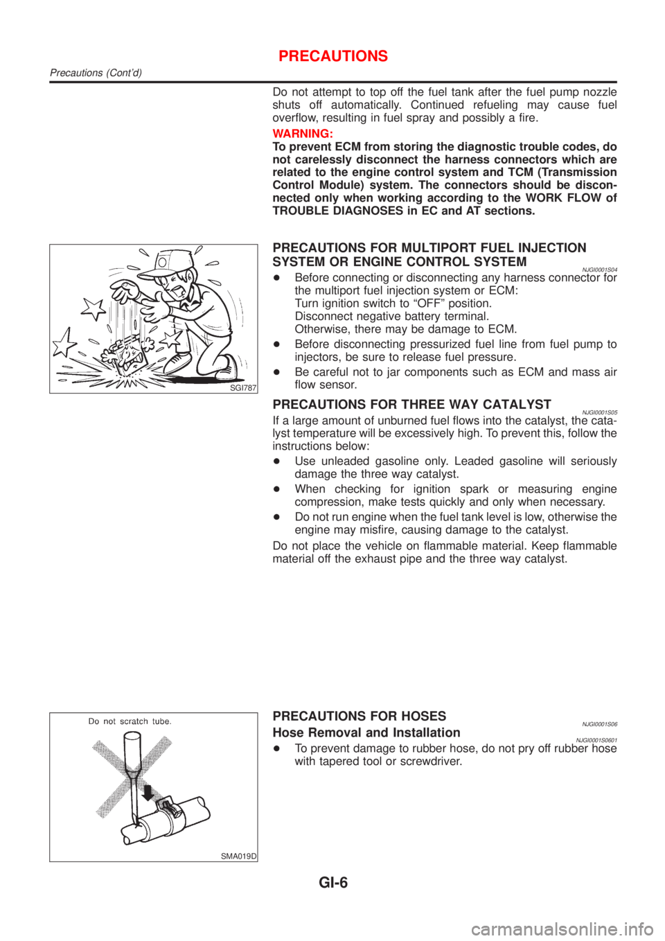
NJGI0001S04+Before connecting or disconnecting any harness connector for
the multiport fuel injection system or ECM:
Turn ignition switch to ªOFFº position.
Disconnect negative battery terminal.
Otherwise, there may be damage to ECM.
+Before disconnecting pressurized fuel line from fuel pump to
injectors, be sure to release fuel pressure.
+Be careful not to jar components such as ECM and mass air
flow sensor.
PRECAUTIONS FOR THREE WAY CATALYSTNJGI0001S05If a large amount of unburned fuel flows into the catalyst, the cata-
lyst temperature will be excessively high. To prevent this, follow the
instructions below:
+Use unleaded gasoline only. Leaded gasoline will seriously
damage the three way catalyst.
+When checking for ignition spark or measuring engine
compression, make tests quickly and only when necessary.
+Do not run engine when the fuel tank level is low, otherwise the
engine may misfire, causing damage to the catalyst.
Do not place the vehicle on flammable material. Keep flammable
material off the exhaust pipe and the three way catalyst.
SMA019D
PRECAUTIONS FOR HOSESNJGI0001S06Hose Removal and InstallationNJGI0001S0601+To prevent damage to rubber hose, do not pry off rubber hose
with tapered tool or screwdriver.
PRECAUTIONS
Precautions (Cont'd)
GI-6
Page 12 of 2493
NJGI0002
+The captionsWARNINGandCAUTIONwarm you of steps that must be followed to prevent personal injury
and/or damage to some part of the vehicle.
WARNINGindicates the possibility of personal injury if instructions are not followed.
CAUTIONindicates the possibility of component damage if instructions are not followed.
BOLD TYPED STATEMENTSexceptWARNINGandCAUTIONgive you helpful information.
+ALPHABETICAL INDEXis provided at the end of this manual so that you can rapidly find the item and
page you are searching for.
+A QUICK REFERENCE INDEX, a black tab (e.g.
) is provided on the first page. You can quickly find
the first page of each section by matching it to the section's black tab.
+THE CONTENTSare listed on the first page of each section.
+THE TITLEis indicated on the upper portion of each page and shows the part or system.
+THE PAGE NUMBERof each section consists of two letters which designate the particular section and a
number (e.g. ªBR-5º).
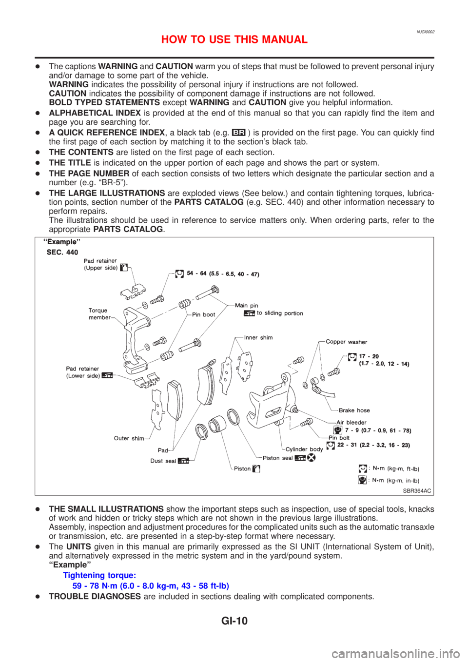
+THE LARGE ILLUSTRATIONSare exploded views (See below.) and contain tightening torques, lubrica-
tion points, section number of thePARTS CATALOG(e.g. SEC. 440) and other information necessary to
perform repairs.
The illustrations should be used in reference to service matters only. When ordering parts, refer to the
appropriatePARTS CATALOG.
SBR364AC
+THE SMALL ILLUSTRATIONSshow the important steps such as inspection, use of special tools, knacks
of work and hidden or tricky steps which are not shown in the previous large illustrations.
Assembly, inspection and adjustment procedures for the complicated units such as the automatic transaxle
or transmission, etc. are presented in a step-by-step format where necessary.
+TheUNITSgiven in this manual are primarily expressed as the SI UNIT (International System of Unit),
and alternatively expressed in the metric system and in the yard/pound system.
ªExampleº
Tightening torque:
59 - 78 N´m (6.0 - 8.0 kg-m, 43 - 58 ft-lb)
+TROUBLE DIAGNOSESare included in sections dealing with complicated components.
HOW TO USE THIS MANUAL
GI-10
Page 38 of 2493
Nickel Metal Hydride Battery Replacement=NJGI0007S06CONSULT-II contains a nickel metal hydride battery. When replacing the battery obey the following:
WARNING:
Replace the nickel metal hydride battery with Genuine CONSULT-II battery only. Use of another bat-
tery may present a risk of fire or explosion. The battery may present a fire or chemical burn hazard if
mistreated. Do not recharge, disassemble of dispose of in fire.
Keep the battery out of reach of children and discard used battery conforming to the local regulations.
Checking EquipmentNJGI0007S07When ordering the below equipment, contact your NISSAN/INFINITI distributor.
Tool name Description
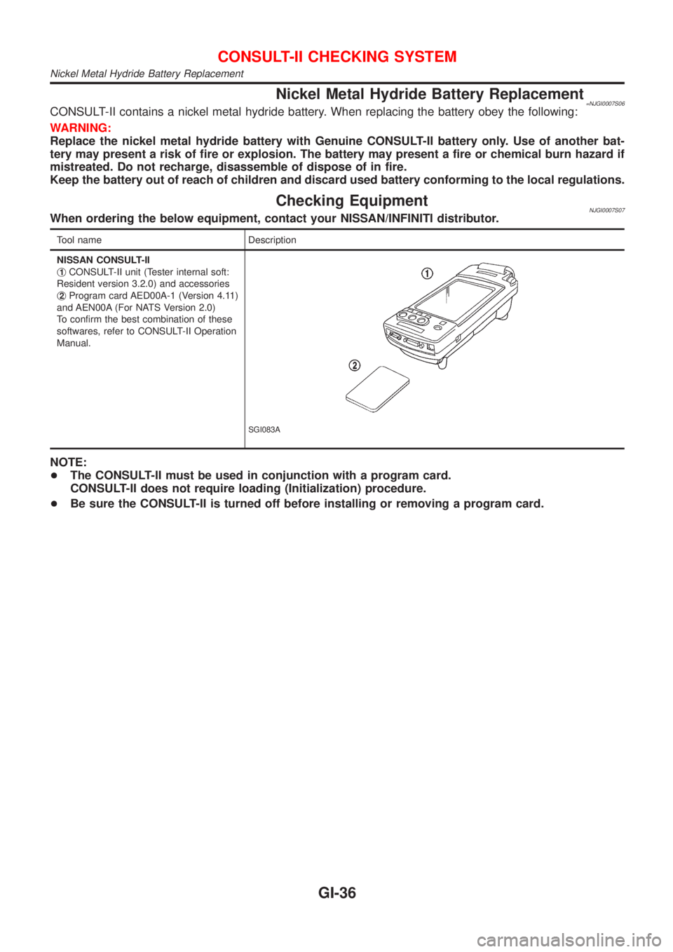
NISSAN CONSULT-II
j
1CONSULT-II unit (Tester internal soft:
Resident version 3.2.0) and accessories
j
2Program card AED00A-1 (Version 4.11)
and AEN00A (For NATS Version 2.0)
To confirm the best combination of these
softwares, refer to CONSULT-II Operation
Manual.
SGI083A
NOTE:
+The CONSULT-II must be used in conjunction with a program card.
CONSULT-II does not require loading (Initialization) procedure.
+Be sure the CONSULT-II is turned off before installing or removing a program card.
CONSULT-II CHECKING SYSTEM
Nickel Metal Hydride Battery Replacement
GI-36
Page 47 of 2493
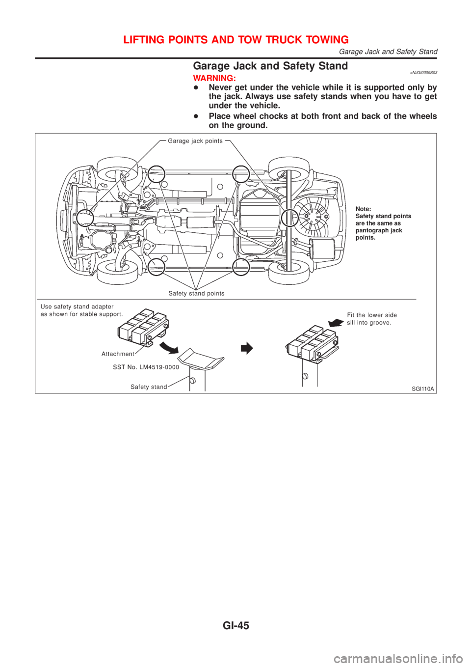
Garage Jack and Safety Stand=NJGI0009S03WARNING:
+Never get under the vehicle while it is supported only by
the jack. Always use safety stands when you have to get
under the vehicle.
+Place wheel chocks at both front and back of the wheels
on the ground.
SGI110A
LIFTING POINTS AND TOW TRUCK TOWING
Garage Jack and Safety Stand
GI-45
Page 48 of 2493
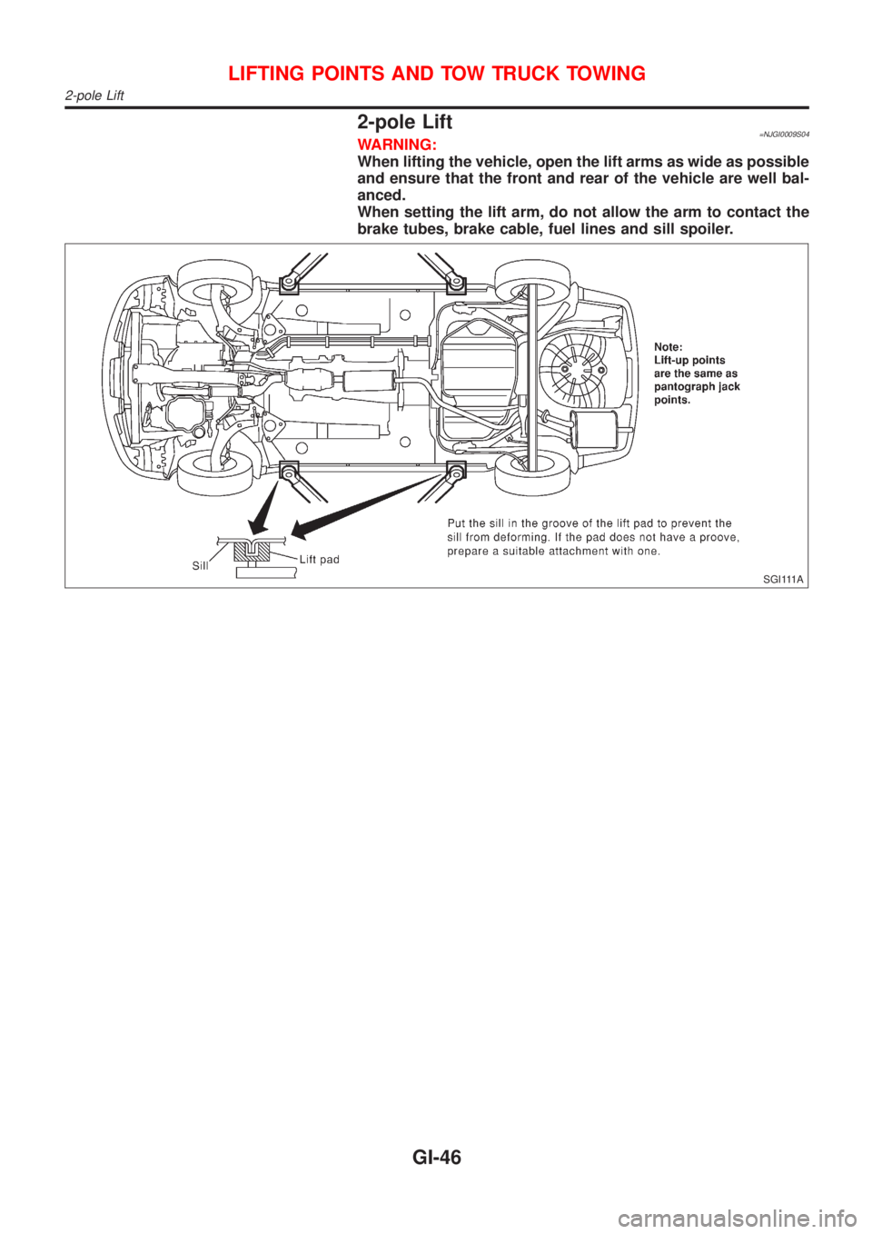
2-pole Lift=NJGI0009S04WARNING:
When lifting the vehicle, open the lift arms as wide as possible
and ensure that the front and rear of the vehicle are well bal-
anced.
When setting the lift arm, do not allow the arm to contact the
brake tubes, brake cable, fuel lines and sill spoiler.
SGI111A
LIFTING POINTS AND TOW TRUCK TOWING
2-pole Lift
GI-46
Page 59 of 2493
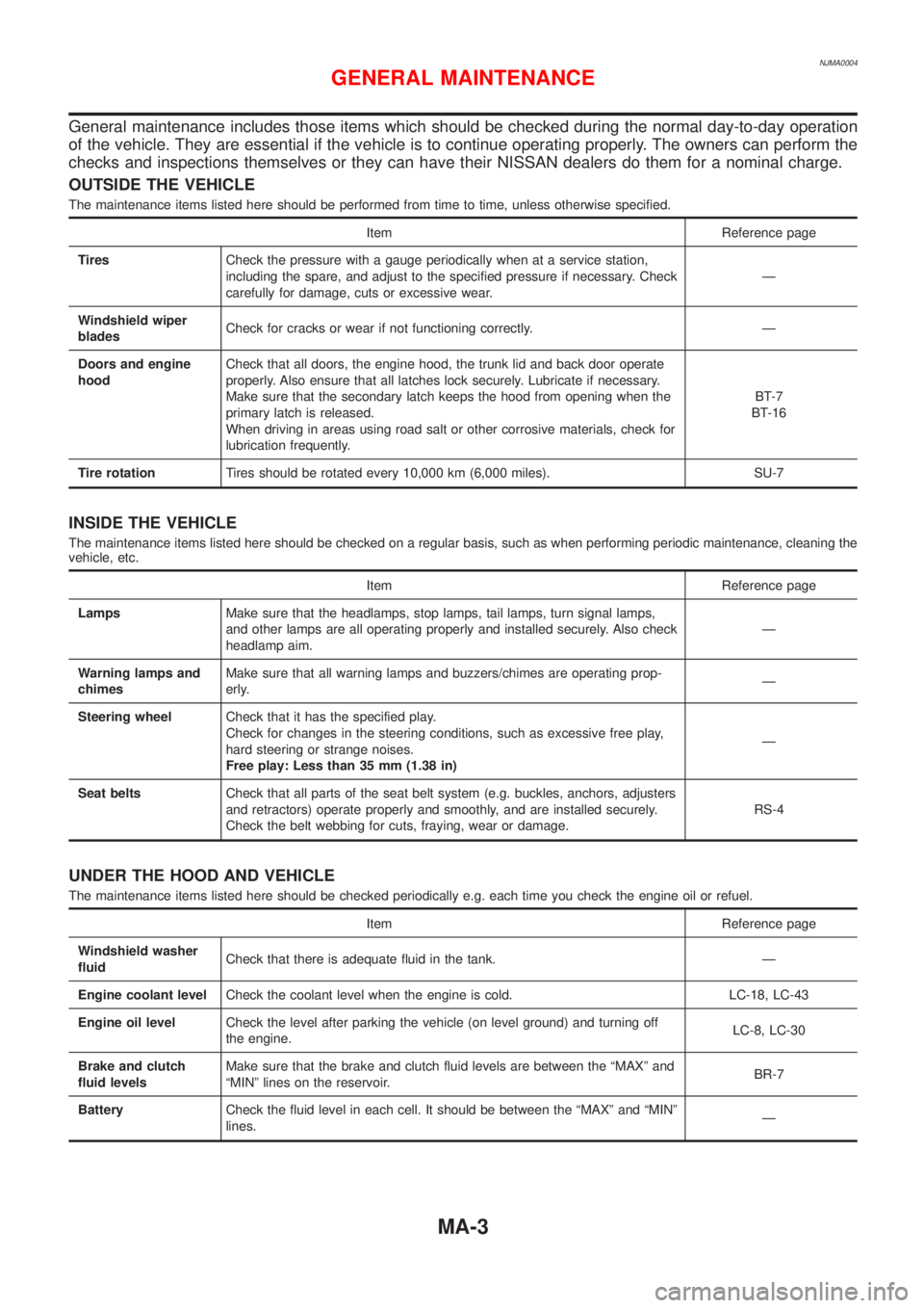
NJMA0004
General maintenance includes those items which should be checked during the normal day-to-day operation
of the vehicle. They are essential if the vehicle is to continue operating properly. The owners can perform the
checks and inspections themselves or they can have their NISSAN dealers do them for a nominal charge.
OUTSIDE THE VEHICLE
The maintenance items listed here should be performed from time to time, unless otherwise specified.
Item Reference page
TiresCheck the pressure with a gauge periodically when at a service station,
including the spare, and adjust to the specified pressure if necessary. Check
carefully for damage, cuts or excessive wear.Ð
Windshield wiper
bladesCheck for cracks or wear if not functioning correctly. Ð
Doors and engine
hoodCheck that all doors, the engine hood, the trunk lid and back door operate
properly. Also ensure that all latches lock securely. Lubricate if necessary.
Make sure that the secondary latch keeps the hood from opening when the
primary latch is released.
When driving in areas using road salt or other corrosive materials, check for
lubrication frequently.BT-7
BT-16
Tire rotationTires should be rotated every 10,000 km (6,000 miles). SU-7
INSIDE THE VEHICLE
The maintenance items listed here should be checked on a regular basis, such as when performing periodic maintenance, cleaning the
vehicle, etc.
Item Reference page
LampsMake sure that the headlamps, stop lamps, tail lamps, turn signal lamps,
and other lamps are all operating properly and installed securely. Also check
headlamp aim.Ð
Warning lamps and
chimesMake sure that all warning lamps and buzzers/chimes are operating prop-
erly.Ð
Steering wheelCheck that it has the specified play.
Check for changes in the steering conditions, such as excessive free play,
hard steering or strange noises.
Free play: Less than 35 mm (1.38 in)Ð
Seat beltsCheck that all parts of the seat belt system (e.g. buckles, anchors, adjusters
and retractors) operate properly and smoothly, and are installed securely.
Check the belt webbing for cuts, fraying, wear or damage.RS-4
UNDER THE HOOD AND VEHICLE
The maintenance items listed here should be checked periodically e.g. each time you check the engine oil or refuel.
Item Reference page
Windshield washer
fluidCheck that there is adequate fluid in the tank. Ð
Engine coolant levelCheck the coolant level when the engine is cold. LC-18, LC-43
Engine oil levelCheck the level after parking the vehicle (on level ground) and turning off
the engine.LC-8, LC-30
Brake and clutch
fluid levelsMake sure that the brake and clutch fluid levels are between the ªMAXº and
ªMINº lines on the reservoir.BR-7
BatteryCheck the fluid level in each cell. It should be between the ªMAXº and ªMINº
lines.Ð
GENERAL MAINTENANCE
MA-3
Page 78 of 2493
SMA089D
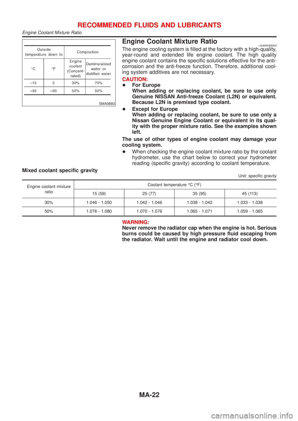
Engine Coolant Mixture Ratio=NJMA0006S03The engine cooling system is filled at the factory with a high-quality,
year-round and extended life engine coolant. The high quality
engine coolant contains the specific solutions effective for the anti-
corrosion and the anti-freeze function. Therefore, additional cool-
ing system additives are not necessary.
CAUTION:
+For Europe
When adding or replacing coolant, be sure to use only
Genuine NISSAN Anti-freeze Coolant (L2N) or equivalent.
Because L2N is premixed type coolant.
+Except for Europe
When adding or replacing coolant, be sure to use only a
Nissan Genuine Engine Coolant or equivalent in its qual-
ity with the proper mixture ratio. See the examples shown
left.
The use of other types of engine coolant may damage your
cooling system.
+When checking the engine coolant mixture ratio by the coolant
hydrometer, use the chart below to correct your hydrometer
reading (specific gravity) according to coolant temperature.
Mixed coolant specific gravity
Unit: specific gravity
Engine coolant mixture
ratioCoolant temperature ÉC (ÉF)
15 (59) 25 (77) 35 (95) 45 (113)
30% 1.046 - 1.050 1.042 - 1.046 1.038 - 1.042 1.033 - 1.038
50% 1.076 - 1.080 1.070 - 1.076 1.065 - 1.071 1.059 - 1.065
WARNING:
Never remove the radiator cap when the engine is hot. Serious
burns could be caused by high pressure fluid escaping from
the radiator. Wait until the engine and radiator cool down.
RECOMMENDED FLUIDS AND LUBRICANTS
Engine Coolant Mixture Ratio
MA-22
Page 128 of 2493
WARNING:
+Position vehicle on a flat and solid surface.
+Place chocks at front and back of rear wheels.
+Do not remove engine until exhaust system has com-
pletely cooled off, otherwise, you may burn yourself
and/or fire may break out in fuel line.
+Before disconnecting fuel hose, release pressure.
Refer to EC-38, ªFuel Pressure Releaseº.
+Be sure to lift engine and transaxle in a safe manner.
+For engines not equipped with engine slingers, attach
proper slingers and bolts described in PARTS CATALOG.
CAUTION:
+When lifting engine, be sure to clear surrounding parts.
Use special care near accelerator wire casing, brake lines
and brake master cylinder.
+When lifting the engine, always use engine slingers in a
safe manner.
+When removing drive shaft, be careful not to damage
grease seal of transaxle.
+Before separating engine and transaxle, remove crank-
shaft position sensor (POS) from the cylinder block
assembly.
+Always be extra careful not to damage edge of crankshaft
position sensor (POS), or signal plate teeth.
Engine cannot be removed separately from transaxle. Remove
engine with transaxle as an assembly.
REMOVALNJEM0022S011. Drain coolant from radiator and cylinder block. Refer to LC-17,
ªChanging Engine Coolantº.
2. Remove coolant reservoir tank and bracket.
3. Drain engine oil.
4. Remove battery and battery tray.
5. Remove air cleaner and air duct.
6. Remove drive belts.
7. Remove alternator and air conditioner compressor from
engine.
8. Remove power steering oil pump from engine and position
aside.
Power steering oil pump does not need to be disconnected
from power steering tubes.
ENGINE ASSEMBLYQG
Removal and Installation (Cont'd)
EM-50
Page 204 of 2493
JEM158G
SEM301G
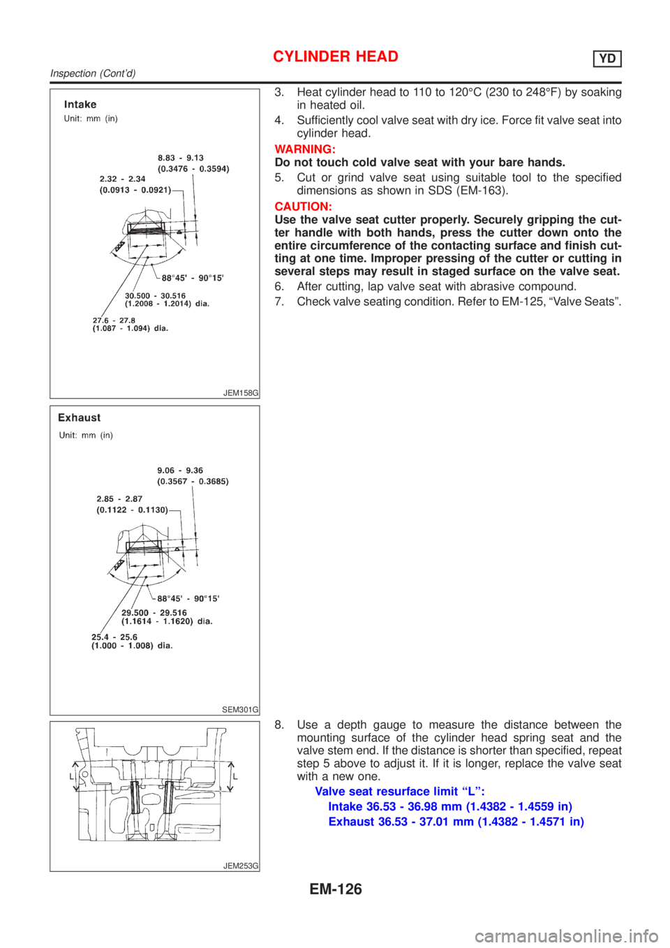
3. Heat cylinder head to 110 to 120ÉC (230 to 248ÉF) by soaking
in heated oil.
4. Sufficiently cool valve seat with dry ice. Force fit valve seat into
cylinder head.
WARNING:
Do not touch cold valve seat with your bare hands.
5. Cut or grind valve seat using suitable tool to the specified
dimensions as shown in SDS (EM-163).
CAUTION:
Use the valve seat cutter properly. Securely gripping the cut-
ter handle with both hands, press the cutter down onto the
entire circumference of the contacting surface and finish cut-
ting at one time. Improper pressing of the cutter or cutting in
several steps may result in staged surface on the valve seat.
6. After cutting, lap valve seat with abrasive compound.
7. Check valve seating condition. Refer to EM-125, ªValve Seatsº.
JEM253G
8. Use a depth gauge to measure the distance between the
mounting surface of the cylinder head spring seat and the
valve stem end. If the distance is shorter than specified, repeat
step 5 above to adjust it. If it is longer, replace the valve seat
with a new one.
Valve seat resurface limit ªLº:
Intake 36.53 - 36.98 mm (1.4382 - 1.4559 in)
Exhaust 36.53 - 37.01 mm (1.4382 - 1.4571 in)
CYLINDER HEADYD
Inspection (Cont'd)
EM-126