lock NISSAN ALMERA N16 2001 Electronic Repair Manual
[x] Cancel search | Manufacturer: NISSAN, Model Year: 2001, Model line: ALMERA N16, Model: NISSAN ALMERA N16 2001Pages: 2493, PDF Size: 66.97 MB
Page 6 of 2493
The security indicator is located on the combi meter. The indicator
blinks when the ignition switch is in ªOFFº or ªACCº position.
Therefore, NATS warns outsiders that the vehicle is equipped with
the anti-theft system.
+When NATS detects trouble, the security indicator lamp lights
up while ignition switch is in ªONº position.
This lighting up indicates that the anti-theft is not functioning,
so prompt service is required.
+When servicing NATS (trouble diagnoses, system initialization
and additional registration of other NATS ignition key IDs),
CONSULT-II hardware and CONSULT-II NATS software is
necessary.
Regarding the procedures of NATS initialization and NATS
ignition key ID registration, refer to CONSULT-II operation
manual, NATS.
Therefore, CONSULT-II NATS software (program card and
operation manual) must be kept strictly confidential to main-
tain the integrity of the anti-theft function.
+When servicing NATS (trouble diagnoses, system initialization
and additional registration of other NATS ignition key IDs), it
may be necessary to re-register original key identification.
Therefore, be sure to receive all keys from vehicle owner. A
maximum of five key IDs can be registered into NATS.
+When failing to start the engine first time using the key of
NATS, start as follows.
a) Leave the ignition key in ªONº position for approximately 5
seconds.
b) Turn ignition key to ªOFFº or ªLOCKº position and wait approxi-
mately 5 seconds.
c) Repeat step 1 and 2 again.
d) Restart the engine while keeping the key separate from any
others on key-chain.
SGI285
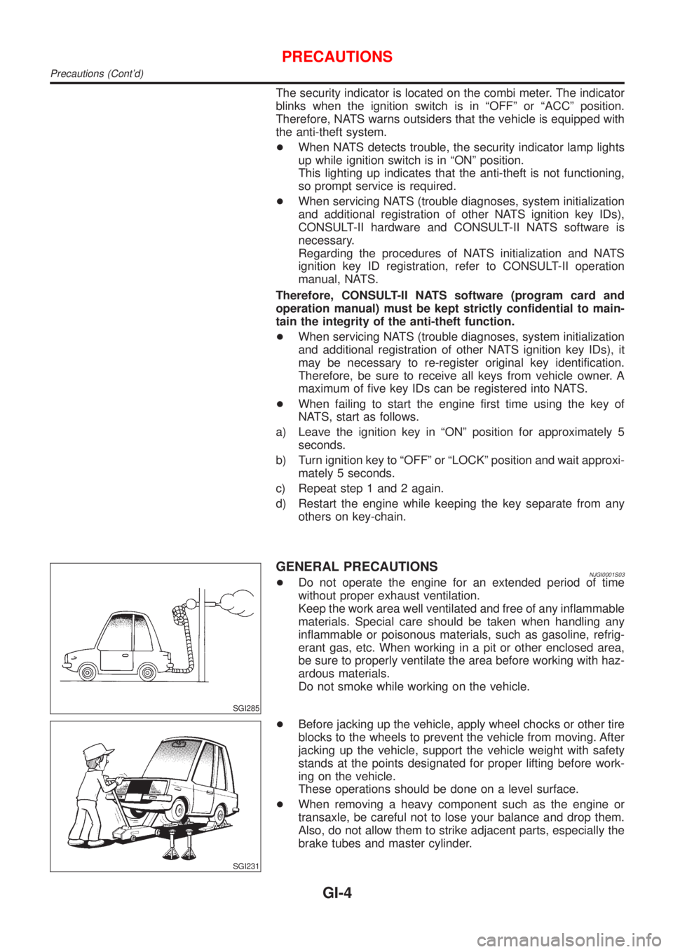
GENERAL PRECAUTIONSNJGI0001S03+Do not operate the engine for an extended period of time
without proper exhaust ventilation.
Keep the work area well ventilated and free of any inflammable
materials. Special care should be taken when handling any
inflammable or poisonous materials, such as gasoline, refrig-
erant gas, etc. When working in a pit or other enclosed area,
be sure to properly ventilate the area before working with haz-
ardous materials.
Do not smoke while working on the vehicle.
SGI231
+Before jacking up the vehicle, apply wheel chocks or other tire
blocks to the wheels to prevent the vehicle from moving. After
jacking up the vehicle, support the vehicle weight with safety
stands at the points designated for proper lifting before work-
ing on the vehicle.
These operations should be done on a level surface.
+When removing a heavy component such as the engine or
transaxle, be careful not to lose your balance and drop them.
Also, do not allow them to strike adjacent parts, especially the
brake tubes and master cylinder.
PRECAUTIONS
Precautions (Cont'd)
GI-4
Page 7 of 2493
SEF289H
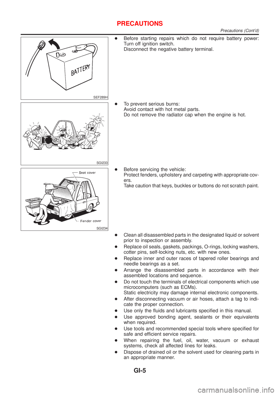
+Before starting repairs which do not require battery power:
Turn off ignition switch.
Disconnect the negative battery terminal.
SGI233
+To prevent serious burns:
Avoid contact with hot metal parts.
Do not remove the radiator cap when the engine is hot.
SGI234
+Before servicing the vehicle:
Protect fenders, upholstery and carpeting with appropriate cov-
ers.
Take caution that keys, buckles or buttons do not scratch paint.
+Clean all disassembled parts in the designated liquid or solvent
prior to inspection or assembly.
+Replace oil seals, gaskets, packings, O-rings, locking washers,
cotter pins, self-locking nuts, etc. with new ones.
+Replace inner and outer races of tapered roller bearings and
needle bearings as a set.
+Arrange the disassembled parts in accordance with their
assembled locations and sequence.
+Do not touch the terminals of electrical components which use
microcomputers (such as ECMs).
Static electricity may damage internal electronic components.
+After disconnecting vacuum or air hoses, attach a tag to indi-
cate the proper connection.
+Use only the fluids and lubricants specified in this manual.
+Use approved bonding agent, sealants or their equivalents
when required.
+Use tools and recommended special tools where specified for
safe and efficient service repairs.
+When repairing the fuel, oil, water, vacuum or exhaust
systems, check all affected lines for leaks.
+Dispose of drained oil or the solvent used for cleaning parts in
an appropriate manner.
PRECAUTIONS
Precautions (Cont'd)
GI-5
Page 18 of 2493
SGI364
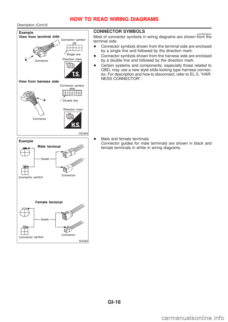
CONNECTOR SYMBOLS=NJGI0003S0201Most of connector symbols in wiring diagrams are shown from the
terminal side.
+Connector symbols shown from the terminal side are enclosed
by a single line and followed by the direction mark.
+Connector symbols shown from the harness side are enclosed
by a double line and followed by the direction mark.
+Certain systems and components, especially those related to
OBD, may use a new style slide-locking type harness connec-
tor. For description and how to disconnect, refer to EL-5, ªHAR-
NESS CONNECTORº.
SGI363
+Male and female terminals
Connector guides for male terminals are shown in black and
female terminals in white in wiring diagrams.
HOW TO READ WIRING DIAGRAMS
Description (Cont'd)
GI-16
Page 22 of 2493
manual.
Fuse block Ð Junction box (J/B)
Fuse block Ð Junction box (J/B) connector number is shown in the
Reference Area of the wiring diagram. For connector terminal and
fuse arrangement, refer to the ªFUSE BLOCK Ð Junction Box
(J/B)º electrical reference page at the end of the manual.
Fuse and fusible link box
For fuse arrangement in the fuse and fusible link box, refer to the
ªFUSE AND FUSIBLE LINK BOXº electrical reference page at the
end of the manual.
Electrical units
Electrical unit connector symbols are shown in the Connector Area
of the wiring diagram.
However, when there is not enough space to show the connector
terminal arrangement in the Connector Area of the wiring diagram,
the electrical unit connector number is shown in the Reference
Area of the wiring diagram. For electrical unit connector terminal
arrangement, refer to the ªELECTRICAL UNITSº electrical refer-
ence page at the end of the manual. Most of the electrical unit
connectors on this page are shown from the harness side of the
connector.
Joint connector
Joint connector symbols are shown in the connector area of the
wiring diagram. For connector internal wiring layout and joint con-
nector terminal arrangement, refer to the ªJOINT CONNECTOR
(J/C)º electrical reference page at the end of the manual.
HOW TO READ WIRING DIAGRAMS
Description (Cont'd)
GI-20
Page 27 of 2493
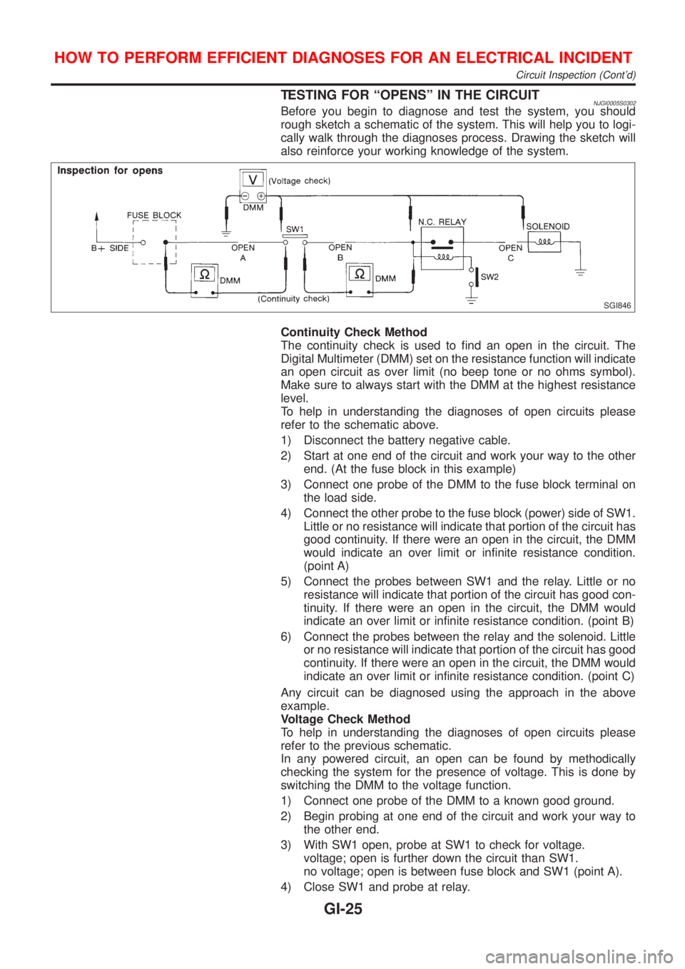
TESTING FOR ªOPENSº IN THE CIRCUITNJGI0005S0302Before you begin to diagnose and test the system, you should
rough sketch a schematic of the system. This will help you to logi-
cally walk through the diagnoses process. Drawing the sketch will
also reinforce your working knowledge of the system.
SGI846
Continuity Check Method
The continuity check is used to find an open in the circuit. The
Digital Multimeter (DMM) set on the resistance function will indicate
an open circuit as over limit (no beep tone or no ohms symbol).
Make sure to always start with the DMM at the highest resistance
level.
To help in understanding the diagnoses of open circuits please
refer to the schematic above.
1) Disconnect the battery negative cable.
2) Start at one end of the circuit and work your way to the other
end. (At the fuse block in this example)
3) Connect one probe of the DMM to the fuse block terminal on
the load side.
4) Connect the other probe to the fuse block (power) side of SW1.
Little or no resistance will indicate that portion of the circuit has
good continuity. If there were an open in the circuit, the DMM
would indicate an over limit or infinite resistance condition.
(point A)
5) Connect the probes between SW1 and the relay. Little or no
resistance will indicate that portion of the circuit has good con-
tinuity. If there were an open in the circuit, the DMM would
indicate an over limit or infinite resistance condition. (point B)
6) Connect the probes between the relay and the solenoid. Little
or no resistance will indicate that portion of the circuit has good
continuity. If there were an open in the circuit, the DMM would
indicate an over limit or infinite resistance condition. (point C)
Any circuit can be diagnosed using the approach in the above
example.
Voltage Check Method
To help in understanding the diagnoses of open circuits please
refer to the previous schematic.
In any powered circuit, an open can be found by methodically
checking the system for the presence of voltage. This is done by
switching the DMM to the voltage function.
1) Connect one probe of the DMM to a known good ground.
2) Begin probing at one end of the circuit and work your way to
the other end.
3) With SW1 open, probe at SW1 to check for voltage.
voltage; open is further down the circuit than SW1.
no voltage; open is between fuse block and SW1 (point A).
4) Close SW1 and probe at relay.
HOW TO PERFORM EFFICIENT DIAGNOSES FOR AN ELECTRICAL INCIDENT
Circuit Inspection (Cont'd)
GI-25
Page 28 of 2493
voltage; open is further down the circuit than the relay.
no voltage; open is between SW1 and relay (point B).
5) Close the relay and probe at the solenoid.
voltage; open is further down the circuit than the solenoid.
no voltage; open is between relay and solenoid (point C).
Any powered circuit can be diagnosed using the approach in the
above example.
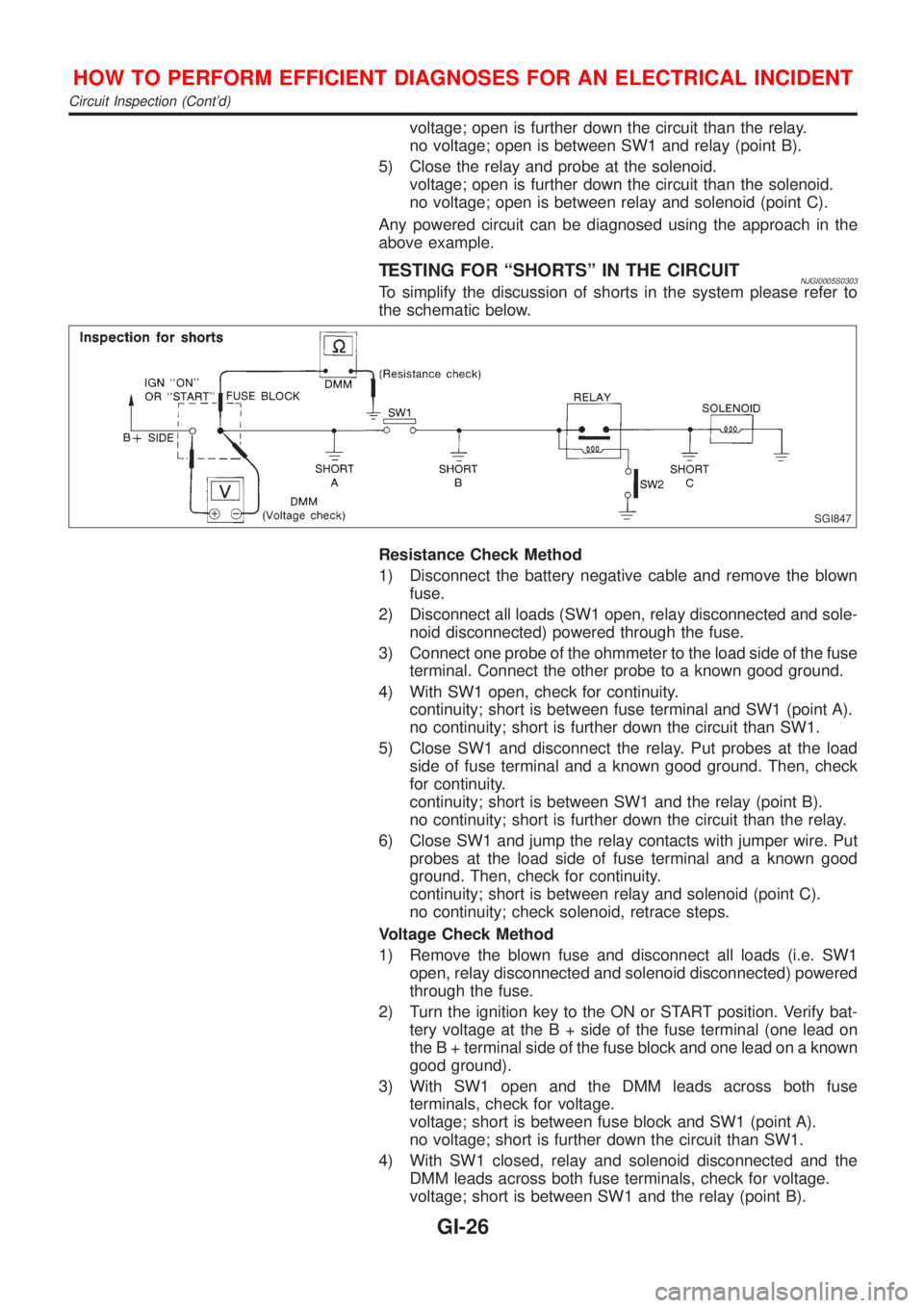
TESTING FOR ªSHORTSº IN THE CIRCUITNJGI0005S0303To simplify the discussion of shorts in the system please refer to
the schematic below.
SGI847
Resistance Check Method
1) Disconnect the battery negative cable and remove the blown
fuse.
2) Disconnect all loads (SW1 open, relay disconnected and sole-
noid disconnected) powered through the fuse.
3) Connect one probe of the ohmmeter to the load side of the fuse
terminal. Connect the other probe to a known good ground.
4) With SW1 open, check for continuity.
continuity; short is between fuse terminal and SW1 (point A).
no continuity; short is further down the circuit than SW1.
5) Close SW1 and disconnect the relay. Put probes at the load
side of fuse terminal and a known good ground. Then, check
for continuity.
continuity; short is between SW1 and the relay (point B).
no continuity; short is further down the circuit than the relay.
6) Close SW1 and jump the relay contacts with jumper wire. Put
probes at the load side of fuse terminal and a known good
ground. Then, check for continuity.
continuity; short is between relay and solenoid (point C).
no continuity; check solenoid, retrace steps.
Voltage Check Method
1) Remove the blown fuse and disconnect all loads (i.e. SW1
open, relay disconnected and solenoid disconnected) powered
through the fuse.
2) Turn the ignition key to the ON or START position. Verify bat-
tery voltage at the B + side of the fuse terminal (one lead on
the B + terminal side of the fuse block and one lead on a known
good ground).
3) With SW1 open and the DMM leads across both fuse
terminals, check for voltage.
voltage; short is between fuse block and SW1 (point A).
no voltage; short is further down the circuit than SW1.
4) With SW1 closed, relay and solenoid disconnected and the
DMM leads across both fuse terminals, check for voltage.
voltage; short is between SW1 and the relay (point B).
HOW TO PERFORM EFFICIENT DIAGNOSES FOR AN ELECTRICAL INCIDENT
Circuit Inspection (Cont'd)
GI-26
Page 29 of 2493
no voltage; short is further down the circuit than the relay.
5) With SW1 closed, relay contacts jumped with fused jumper
wire check for voltage.
voltage; short is down the circuit of the relay or between the
relay and the disconnected solenoid (point C).
no voltage; retrace steps and check power to fuse block.
GROUND INSPECTIONNJGI0005S0304Ground connections are very important to the proper operation of
electrical and electronic circuits. Ground connections are often
exposed to moisture, dirt and other corrosive elements. The corro-
sion (rust) can become an unwanted resistance. This unwanted
resistance can change the way a circuit works.
Electronically controlled circuits are very sensitive to proper
grounding. A loose or corroded ground can drastically affect an
electronically controlled circuit. A poor or corroded ground can eas-
ily affect the circuit. Even when the ground connection looks clean,
there can be a thin film of rust on the surface.
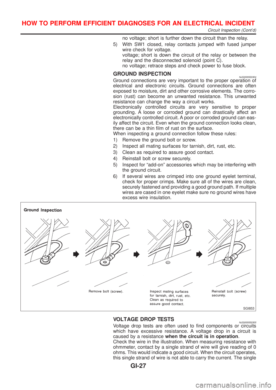
When inspecting a ground connection follow these rules:
1) Remove the ground bolt or screw.
2) Inspect all mating surfaces for tarnish, dirt, rust, etc.
3) Clean as required to assure good contact.
4) Reinstall bolt or screw securely.
5) Inspect for ªadd-onº accessories which may be interfering with
the ground circuit.
6) If several wires are crimped into one ground eyelet terminal,
check for proper crimps. Make sure all of the wires are clean,
securely fastened and providing a good ground path. If multiple
wires are cased in one eyelet make sure no ground wires have
excess wire insulation.
SGI853
VOLTAGE DROP TESTSNJGI0005S0305Voltage drop tests are often used to find components or circuits
which have excessive resistance. A voltage drop in a circuit is
caused by a resistancewhen the circuit is in operation.
Check the wire in the illustration. When measuring resistance with
ohmmeter, contact by a single strand of wire will give reading of 0
ohms. This would indicate a good circuit. When the circuit operates,
this single strand of wire is not able to carry the current. The single
HOW TO PERFORM EFFICIENT DIAGNOSES FOR AN ELECTRICAL INCIDENT
Circuit Inspection (Cont'd)
GI-27
Page 37 of 2493
NJGI0007
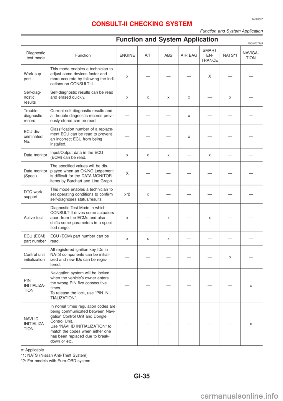
Function and System ApplicationNJGI0007S05
Diagnostic
test modeFunction ENGINE A/T ABS AIR BAGSMART
EN-
TRANCENATS*1NAVIGA-
TION
Work sup-
portThis mode enables a technician to
adjust some devices faster and
more accurate by following the indi-
cations on CONSULT-II.x ÐÐÐXÐÐ
Self-diag-
nostic
resultsSelf-diagnostic results can be read
and erased quickly.x x x xÐxÐ
Trouble
diagnostic
recordCurrent self-diagnostic results and
all trouble diagnostic records previ-
ously stored can be read.ÐÐÐ x ÐÐÐ
ECU dis-
criminated
No.Classification number of a replace-
ment ECU can be read to prevent
an incorrect ECU from being
installed.ÐÐÐ x ÐÐÐ
Data monitorInput/Output data in the ECU
(ECM) can be read.x x xÐxÐÐ
Data monitor
(Spec.)The specified values will be dis-
played when an OK/NG judgement
is difficult for the DATA MONITOR
items by Barchart and Line Graph.X ÐÐÐÐÐÐ
DTC work
supportThis mode enables a technician to
set operating conditions to confirm
self-diagnoses status/results.x*2x ÐÐÐÐÐ
Active testDiagnostic Test Mode in which
CONSULT-II drives some actuators
apart from the ECMs and also
shifts some parameters in a speci-
fied range.xÐxÐxÐÐ
ECU (ECM)
part numberECU (ECM) part number can be
read.x x x ÐÐÐÐ
Control unit
initializationAll registered ignition key IDs in
NATS components can be initial-
ized and new IDs can be regis-
tered.ÐÐÐÐÐ x Ð
PIN
INITIALIZA-
TIONNavigation system will be locked
when the vehicle's owner enters
the wrong PIN five consecutive
times.
To release the lock, use ªPIN INI-
TIALIZATIONº.ÐÐÐÐÐÐ x
NAVI ID
INITIALIZA-
TIONIn nomal times regulation codes are
being communicated between Navi-
gation Control Unit and Dongle
Control Unit.
Use ªNAVI ID INITIALIZATIONº to
match the codes when either one
has been replaced due to break-
down or etc.ÐÐÐÐÐÐ x
x: Applicable
*1: NATS (Nissan Anti-Theft System)
*2: For models with Euro-OBD system
CONSULT-II CHECKING SYSTEM
Function and System Application
GI-35
Page 55 of 2493
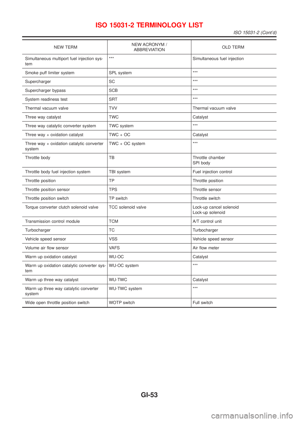
NEW TERMNEW ACRONYM /
ABBREVIATIONOLD TERM
Simultaneous multiport fuel injection sys-
tem*** Simultaneous fuel injection
Smoke puff limiter system SPL system ***
Supercharger SC ***
Supercharger bypass SCB ***
System readiness test SRT ***
Thermal vacuum valve TVV Thermal vacuum valve
Three way catalyst TWC Catalyst
Three way catalytic converter system TWC system ***
Three way + oxidation catalyst TWC + OC Catalyst
Three way + oxidation catalytic converter
systemTWC + OC system ***
Throttle body TB Throttle chamber
SPI body
Throttle body fuel injection system TBI system Fuel injection control
Throttle position TP Throttle position
Throttle position sensor TPS Throttle sensor
Throttle position switch TP switch Throttle switch
Torque converter clutch solenoid valve TCC solenoid valve Lock-up cancel solenoid
Lock-up solenoid
Transmission control module TCM A/T control unit
Turbocharger TC Turbocharger
Vehicle speed sensor VSS Vehicle speed sensor
Volume air flow sensor VAFS Air flow meter
Warm up oxidation catalyst WU-OC Catalyst
Warm up oxidation catalytic converter sys-
temWU-OC system ***
Warm up three way catalyst WU-TWC Catalyst
Warm up three way catalytic converter
systemWU-TWC system ***
Wide open throttle position switch WOTP switch Full switch
ISO 15031-2 TERMINOLOGY LIST
ISO 15031-2 (Cont'd)
GI-53
Page 58 of 2493
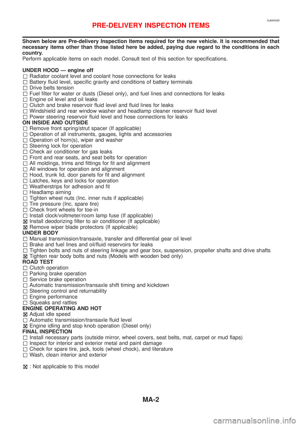
NJMA0036
Shown below are Pre-delivery Inspection Items required for the new vehicle. It is recommended that
necessary items other than those listed here be added, paying due regard to the conditions in each
country.
Perform applicable items on each model. Consult text of this section for specifications.
UNDER HOOD Ð engine off
Radiator coolant level and coolant hose connections for leaks
Battery fluid level, specific gravity and conditions of battery terminals
Drive belts tension
Fuel filter for water or dusts (Diesel only), and fuel lines and connections for leaks
Engine oil level and oil leaks
Clutch and brake reservoir fluid level and fluid lines for leaks
Windshield and rear window washer and headlamp cleaner reservoir fluid level
Power steering reservoir fluid level and hose connections for leaks
ON INSIDE AND OUTSIDE
Remove front spring/strut spacer (If applicable)
Operation of all instruments, gauges, lights and accessories
Operation of horn(s), wiper and washer
Steering lock for operation
Check air conditioner for gas leaks
Front and rear seats, and seat belts for operation
All moldings, trims and fittings for fit and alignment
All windows for operation and alignment
Hood, trunk lid, door panels for fit and alignment
Latches, keys and locks for operation
Weatherstrips for adhesion and fit
Headlamp aiming
Tighten wheel nuts (Inc. inner nuts if applicable)
Tire pressure (Inc. spare tire)
Check front wheels for toe-in
Install clock/voltmeter/room lamp fuse (If applicable)
Install deodorizing filter to air conditioner (If applicable)
Remove wiper blade protectors (If applicable)
UNDER BODY
Manual transmission/transaxle, transfer and differential gear oil level
Brake and fuel lines and oil/fluid reservoirs for leaks
Tighten bolts and nuts of steering linkage and gear box, suspension, propeller shafts and drive shafts
Tighten rear body bolts and nuts (Models with wooden bed only)
ROAD TEST
Clutch operation
Parking brake operation
Service brake operation
Automatic transmission/transaxle shift timing and kickdown
Steering control and returnability
Engine performance
Squeaks and rattles
ENGINE OPERATING AND HOT
Adjust idle speed
Automatic transmission/transaxle fluid level
Engine idling and stop knob operation (Diesel only)
FINAL INSPECTION
Install necessary parts (outside mirror, wheel covers, seat belts, mat, carpet or mud flaps)
Inspect for interior and exterior metal and paint damage
Check for spare tire, jack, tools (wheel chock), and literature
Wash, clean interior and exterior
: Not applicable to this model
PRE-DELIVERY INSPECTION ITEMS
MA-2