rear view mirror NISSAN ALMERA N16 2001 Electronic Repair Manual
[x] Cancel search | Manufacturer: NISSAN, Model Year: 2001, Model line: ALMERA N16, Model: NISSAN ALMERA N16 2001Pages: 2493, PDF Size: 66.97 MB
Page 1895 of 2493

BODY & TRIM
SECTION
BT
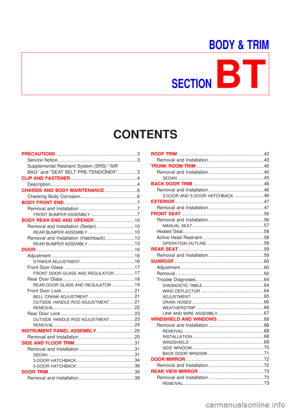
CONTENTS
PRECAUTIONS...............................................................3
Service Notice..............................................................3
Supplemental Restraint System (SRS)²AIR
BAG²and²SEAT BELT PRE-TENSIONER²...............3
CLIP AND FASTENER....................................................4
Description ...................................................................4
CHASSIS AND BODY MAINTENANCE.........................6
Checking Body Corrosion ............................................6
BODY FRONT END.........................................................7
Removal and Installation .............................................7
FRONT BUMPER ASSEMBLY....................................7
BODY REAR END AND OPENER................................10
Removal and Installation (Sedan) .............................10
REAR BUMPER ASSEMBLY....................................10
Removal and Installation (Hatchback).......................13
REAR BUMPER ASSEMBLY....................................13
DOOR.............................................................................16
Adjustment .................................................................16
STRIKER ADJUSTMENT..........................................16
Front Door Glass .......................................................17
FRONT DOOR GLASS AND REGULATOR................17
Rear Door Glass ........................................................18
REAR DOOR GLASS AND REGULATOR..................19
Front Door Lock .........................................................21
BELL CRANK ADJUSTMENT....................................21
OUTSIDE HANDLE ROD ADJUSTMENT...................21
REMOVAL...............................................................22
Rear Door Lock .........................................................23
OUTSIDE HANDLE ROD ADJUSTMENT...................23
REMOVAL...............................................................24
INSTRUMENT PANEL ASSEMBLY.............................25
Removal and Installation ...........................................25
SIDE AND FLOOR TRIM...............................................31
Removal and Installation ...........................................31
SEDAN...................................................................31
3-DOOR HATCHBACK.............................................34
5-DOOR HATCHBACK.............................................36
DOOR TRIM...................................................................39
Removal and Installation ...........................................39ROOF TRIM...................................................................43
Removal and Installation ...........................................43
TRUNK ROOM TRIM.....................................................45
Removal and Installation ...........................................45
SEDAN...................................................................45
BACK DOOR TRIM.......................................................46
Removal and Installation ...........................................46
3-DOOR AND 5-DOOR HATCHBACK.......................46
EXTERIOR.....................................................................47
Removal and Installation ...........................................47
FRONT SEAT................................................................56
Removal and Installation ...........................................56
MANUAL SEAT........................................................57
Heated Seat ...............................................................58
Active Head Restraint ................................................58
OPERATION OUTLINE............................................58
REAR SEAT...................................................................59
Removal and Installation ...........................................59
SUNROOF......................................................................60
Adjustment .................................................................60
Removal .....................................................................60
Trouble Diagnoses.....................................................64
DIAGNOSTIC TABLE................................................64
WIND DEFLECTOR.................................................64
ADJUSTMENT.........................................................65
DRAIN HOSES........................................................66
WEATHERSTRIP.....................................................66
LINK AND WIRE ASSEMBLY....................................67
WINDSHIELD AND WINDOWS....................................68
Removal and Installation ...........................................68
REMOVAL...............................................................68
INSTALLATION........................................................68
WINDSHIELD..........................................................69
SIDE WINDOW........................................................70
BACK DOOR WINDOW............................................71
DOOR MIRROR.............................................................72
Removal and Installation ...........................................72
REAR VIEW MIRROR...................................................73
Removal and Installation ...........................................73
REMOVAL...............................................................73
Page 1966 of 2493

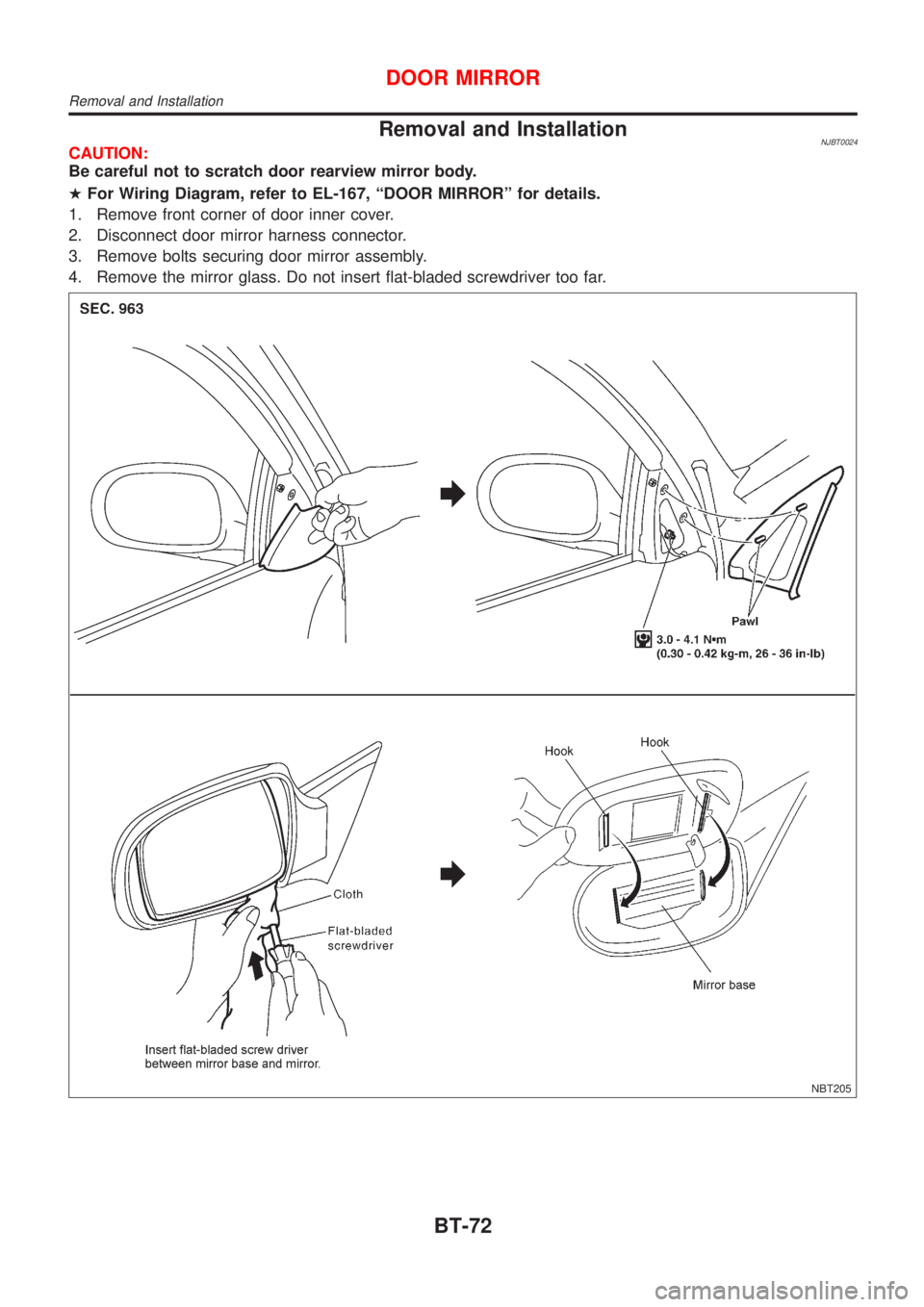
Removal and InstallationNJBT0024CAUTION:
Be careful not to scratch door rearview mirror body.
HFor Wiring Diagram, refer to EL-167, ªDOOR MIRRORº for details.
1. Remove front corner of door inner cover.
2. Disconnect door mirror harness connector.
3. Remove bolts securing door mirror assembly.
4. Remove the mirror glass. Do not insert flat-bladed screwdriver too far.
NBT205
DOOR MIRROR
Removal and Installation
BT-72
Page 1967 of 2493

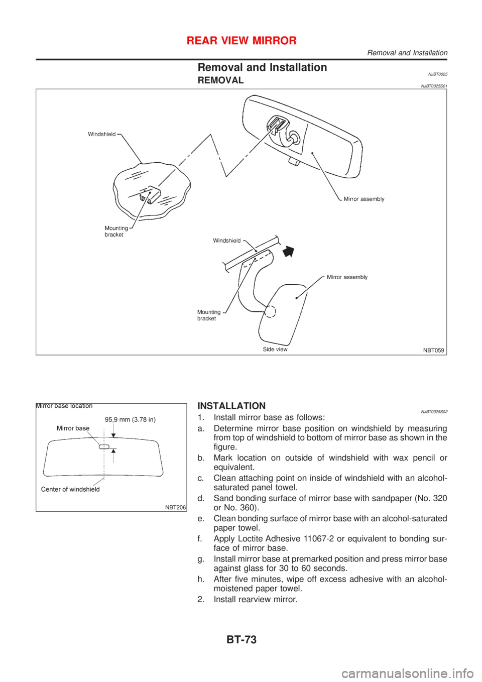
Removal and InstallationNJBT0025REMOVALNJBT0025S01
NBT059
NBT206
INSTALLATIONNJBT0025S021. Install mirror base as follows:
a. Determine mirror base position on windshield by measuring
from top of windshield to bottom of mirror base as shown in the
figure.
b. Mark location on outside of windshield with wax pencil or
equivalent.
c. Clean attaching point on inside of windshield with an alcohol-
saturated panel towel.
d. Sand bonding surface of mirror base with sandpaper (No. 320
or No. 360).
e. Clean bonding surface of mirror base with an alcohol-saturated
paper towel.
f. Apply Loctite Adhesive 11067-2 or equivalent to bonding sur-
face of mirror base.
g. Install mirror base at premarked position and press mirror base
against glass for 30 to 60 seconds.
h. After five minutes, wipe off excess adhesive with an alcohol-
moistened paper towel.
2. Install rearview mirror.
REAR VIEW MIRROR
Removal and Installation
BT-73