relays NISSAN ALMERA N16 2001 Electronic Repair Manual
[x] Cancel search | Manufacturer: NISSAN, Model Year: 2001, Model line: ALMERA N16, Model: NISSAN ALMERA N16 2001Pages: 2493, PDF Size: 66.97 MB
Page 24 of 2493
Incident Simulation TestsNJGI0005S02INTRODUCTIONNJGI0005S0201Sometimes the symptom is not present when the vehicle is brought
in for service. If possible, re-create the conditions present at the
time of the incident. Doing so may help avoid a No Trouble Found
Diagnoses. The following section illustrates ways to simulate the
conditions/environment under which the owner experiences an
electrical incident.
The section is broken into the six following topics:
+Vehicle vibration
+Heat sensitive
+Freezing
+Water intrusion
+Electrical load
+Cold or hot start up
Get a thorough description of the incident from the customer. It is
important for simulating the conditions of the problem.
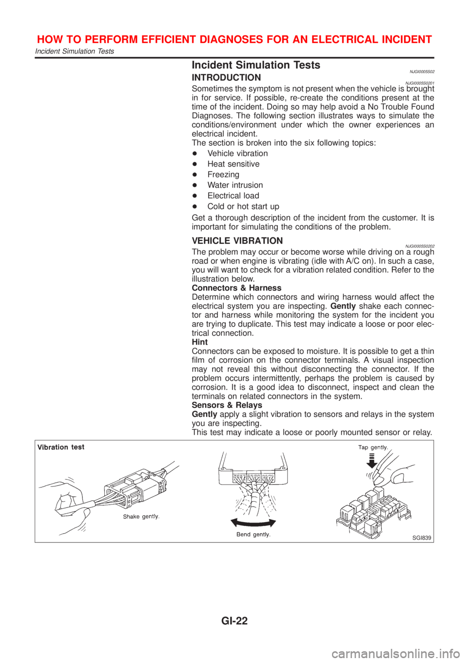
VEHICLE VIBRATIONNJGI0005S0202The problem may occur or become worse while driving on a rough
road or when engine is vibrating (idle with A/C on). In such a case,
you will want to check for a vibration related condition. Refer to the
illustration below.
Connectors & Harness
Determine which connectors and wiring harness would affect the
electrical system you are inspecting.Gentlyshake each connec-
tor and harness while monitoring the system for the incident you
are trying to duplicate. This test may indicate a loose or poor elec-
trical connection.
Hint
Connectors can be exposed to moisture. It is possible to get a thin
film of corrosion on the connector terminals. A visual inspection
may not reveal this without disconnecting the connector. If the
problem occurs intermittently, perhaps the problem is caused by
corrosion. It is a good idea to disconnect, inspect and clean the
terminals on related connectors in the system.
Sensors & Relays
Gentlyapply a slight vibration to sensors and relays in the system
you are inspecting.
This test may indicate a loose or poorly mounted sensor or relay.
SGI839
HOW TO PERFORM EFFICIENT DIAGNOSES FOR AN ELECTRICAL INCIDENT
Incident Simulation Tests
GI-22
Page 918 of 2493
Diagnostic ProcedureNJEC0666
1 INSPECTION START
Do you have CONSULT-II?
YesorNo
Ye s©GO TO 2.
No©GO TO 4.
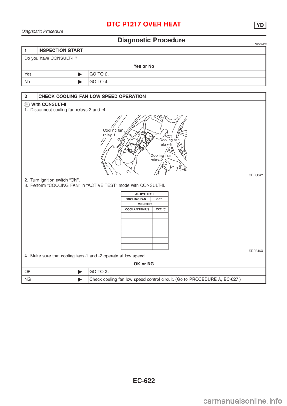
2 CHECK COOLING FAN LOW SPEED OPERATION
With CONSULT-II
1. Disconnect cooling fan relays-2 and -4.
SEF384Y
2. Turn ignition switch ªONº.
3. Perform ªCOOLING FANº in ªACTIVE TESTº mode with CONSULT-II.
SEF646X
4. Make sure that cooling fans-1 and -2 operate at low speed.
OK or NG
OK©GO TO 3.
NG©Check cooling fan low speed control circuit. (Go to PROCEDURE A, EC-627.)
DTC P1217 OVER HEATYD
Diagnostic Procedure
EC-622
Page 919 of 2493
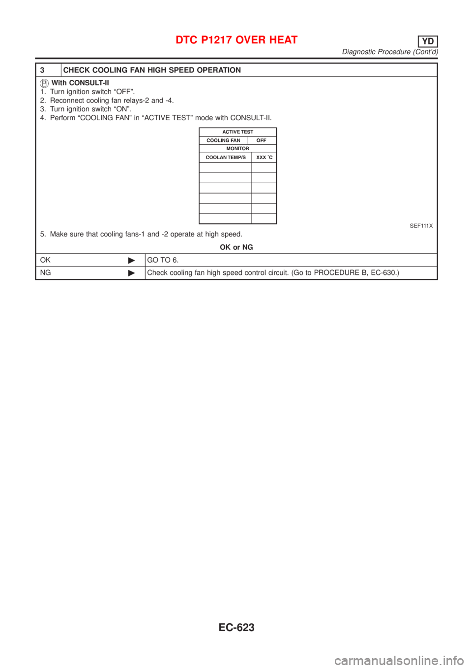
3 CHECK COOLING FAN HIGH SPEED OPERATION
With CONSULT-II
1. Turn ignition switch ªOFFº.
2. Reconnect cooling fan relays-2 and -4.
3. Turn ignition switch ªONº.
4. Perform ªCOOLING FANº in ªACTIVE TESTº mode with CONSULT-II.
SEF111X
5. Make sure that cooling fans-1 and -2 operate at high speed.
OK or NG
OK©GO TO 6.
NG©Check cooling fan high speed control circuit. (Go to PROCEDURE B, EC-630.)
DTC P1217 OVER HEATYD
Diagnostic Procedure (Cont'd)
EC-623
Page 920 of 2493
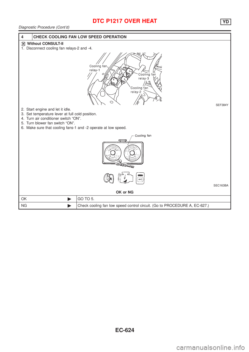
4 CHECK COOLING FAN LOW SPEED OPERATION
Without CONSULT-II
1. Disconnect cooling fan relays-2 and -4.
SEF384Y
2. Start engine and let it idle.
3. Set temperature lever at full cold position.
4. Turn air conditioner switch ªONº.
5. Turn blower fan switch ªONº.
6. Make sure that cooling fans-1 and -2 operate at low speed.
SEC163BA
OK or NG
OK©GO TO 5.
NG©Check cooling fan low speed control circuit. (Go to PROCEDURE A, EC-627.)
DTC P1217 OVER HEATYD
Diagnostic Procedure (Cont'd)
EC-624
Page 921 of 2493
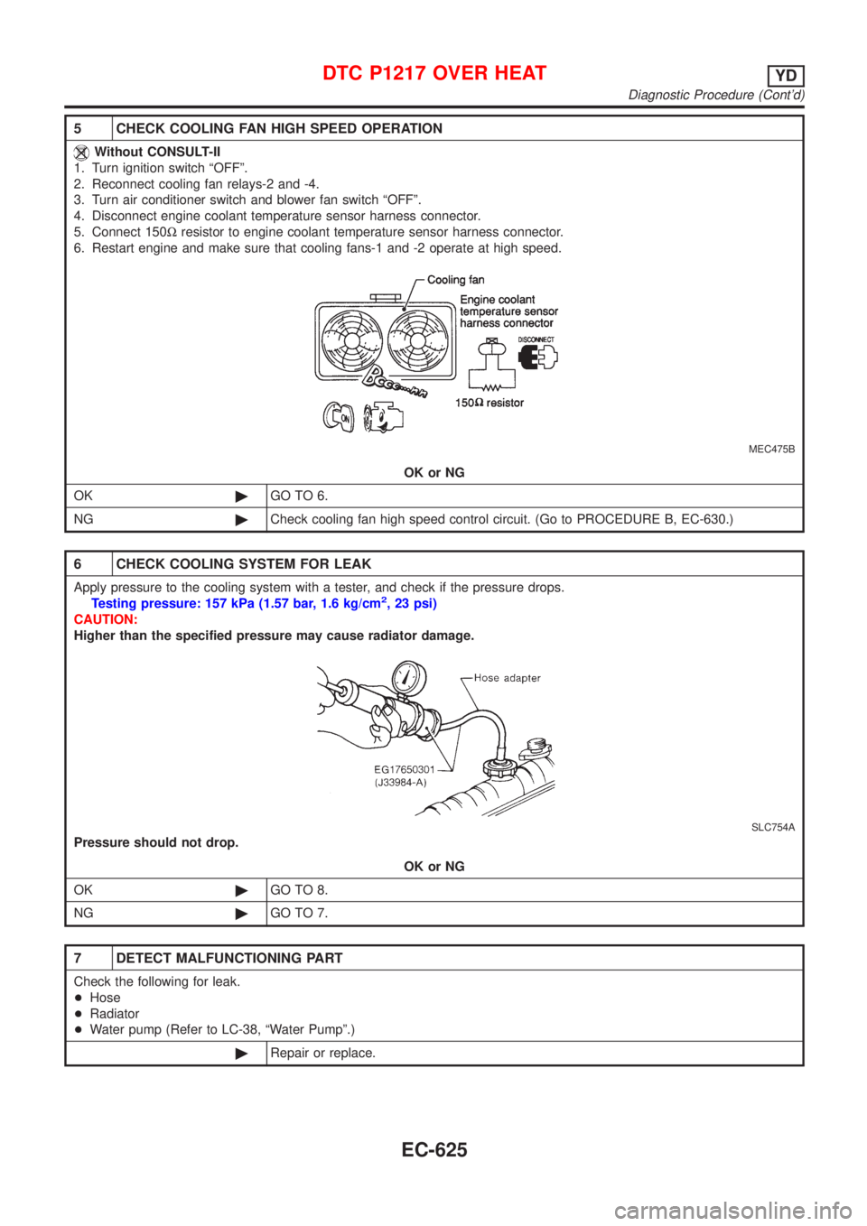
5 CHECK COOLING FAN HIGH SPEED OPERATION
Without CONSULT-II
1. Turn ignition switch ªOFFº.
2. Reconnect cooling fan relays-2 and -4.
3. Turn air conditioner switch and blower fan switch ªOFFº.
4. Disconnect engine coolant temperature sensor harness connector.
5. Connect 150Wresistor to engine coolant temperature sensor harness connector.
6. Restart engine and make sure that cooling fans-1 and -2 operate at high speed.
MEC475B
OK or NG
OK©GO TO 6.
NG©Check cooling fan high speed control circuit. (Go to PROCEDURE B, EC-630.)
6 CHECK COOLING SYSTEM FOR LEAK
Apply pressure to the cooling system with a tester, and check if the pressure drops.
Testing pressure: 157 kPa (1.57 bar, 1.6 kg/cm2, 23 psi)
CAUTION:
Higher than the specified pressure may cause radiator damage.
SLC754A
Pressure should not drop.
OK or NG
OK©GO TO 8.
NG©GO TO 7.
7 DETECT MALFUNCTIONING PART
Check the following for leak.
+Hose
+Radiator
+Water pump (Refer to LC-38, ªWater Pumpº.)
©Repair or replace.
DTC P1217 OVER HEATYD
Diagnostic Procedure (Cont'd)
EC-625
Page 924 of 2493
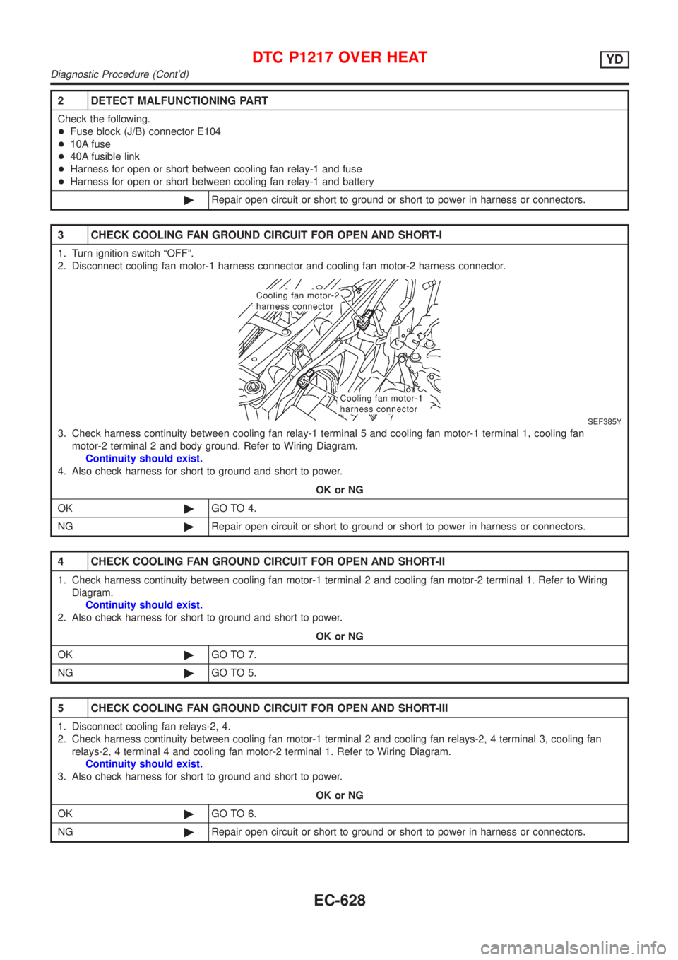
2 DETECT MALFUNCTIONING PART
Check the following.
+Fuse block (J/B) connector E104
+10A fuse
+40A fusible link
+Harness for open or short between cooling fan relay-1 and fuse
+Harness for open or short between cooling fan relay-1 and battery
©Repair open circuit or short to ground or short to power in harness or connectors.
3 CHECK COOLING FAN GROUND CIRCUIT FOR OPEN AND SHORT-I
1. Turn ignition switch ªOFFº.
2. Disconnect cooling fan motor-1 harness connector and cooling fan motor-2 harness connector.
SEF385Y
3. Check harness continuity between cooling fan relay-1 terminal 5 and cooling fan motor-1 terminal 1, cooling fan
motor-2 terminal 2 and body ground. Refer to Wiring Diagram.
Continuity should exist.
4. Also check harness for short to ground and short to power.
OK or NG
OK©GO TO 4.
NG©Repair open circuit or short to ground or short to power in harness or connectors.
4 CHECK COOLING FAN GROUND CIRCUIT FOR OPEN AND SHORT-II
1. Check harness continuity between cooling fan motor-1 terminal 2 and cooling fan motor-2 terminal 1. Refer to Wiring
Diagram.
Continuity should exist.
2. Also check harness for short to ground and short to power.
OK or NG
OK©GO TO 7.
NG©GO TO 5.
5 CHECK COOLING FAN GROUND CIRCUIT FOR OPEN AND SHORT-III
1. Disconnect cooling fan relays-2, 4.
2. Check harness continuity between cooling fan motor-1 terminal 2 and cooling fan relays-2, 4 terminal 3, cooling fan
relays-2, 4 terminal 4 and cooling fan motor-2 terminal 1. Refer to Wiring Diagram.
Continuity should exist.
3. Also check harness for short to ground and short to power.
OK or NG
OK©GO TO 6.
NG©Repair open circuit or short to ground or short to power in harness or connectors.
DTC P1217 OVER HEATYD
Diagnostic Procedure (Cont'd)
EC-628
Page 925 of 2493
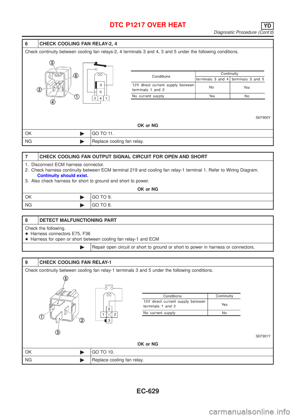
6 CHECK COOLING FAN RELAY-2, 4
Check continuity between cooling fan relays-2, 4 terminals 3 and 4, 3 and 5 under the following conditions.
SEF900Y
OK or NG
OK©GO TO 11.
NG©Replace cooling fan relay.
7 CHECK COOLING FAN OUTPUT SIGNAL CIRCUIT FOR OPEN AND SHORT
1. Disconnect ECM harness connector.
2. Check harness continuity between ECM terminal 219 and cooling fan relay-1 terminal 1. Refer to Wiring Diagram.
Continuity should exist.
3. Also check harness for short to ground and short to power.
OK or NG
OK©GO TO 9.
NG©GO TO 8.
8 DETECT MALFUNCTIONING PART
Check the following.
+Harness connectors E75, F36
+Harness for open or short between cooling fan relay-1 and ECM
©Repair open circuit or short to ground or short to power in harness or connectors.
9 CHECK COOLING FAN RELAY-1
Check continuity between cooling fan relay-1 terminals 3 and 5 under the following conditions.
SEF901Y
OK or NG
OK©GO TO 10.
NG©Replace cooling fan relay.
DTC P1217 OVER HEATYD
Diagnostic Procedure (Cont'd)
EC-629
Page 926 of 2493
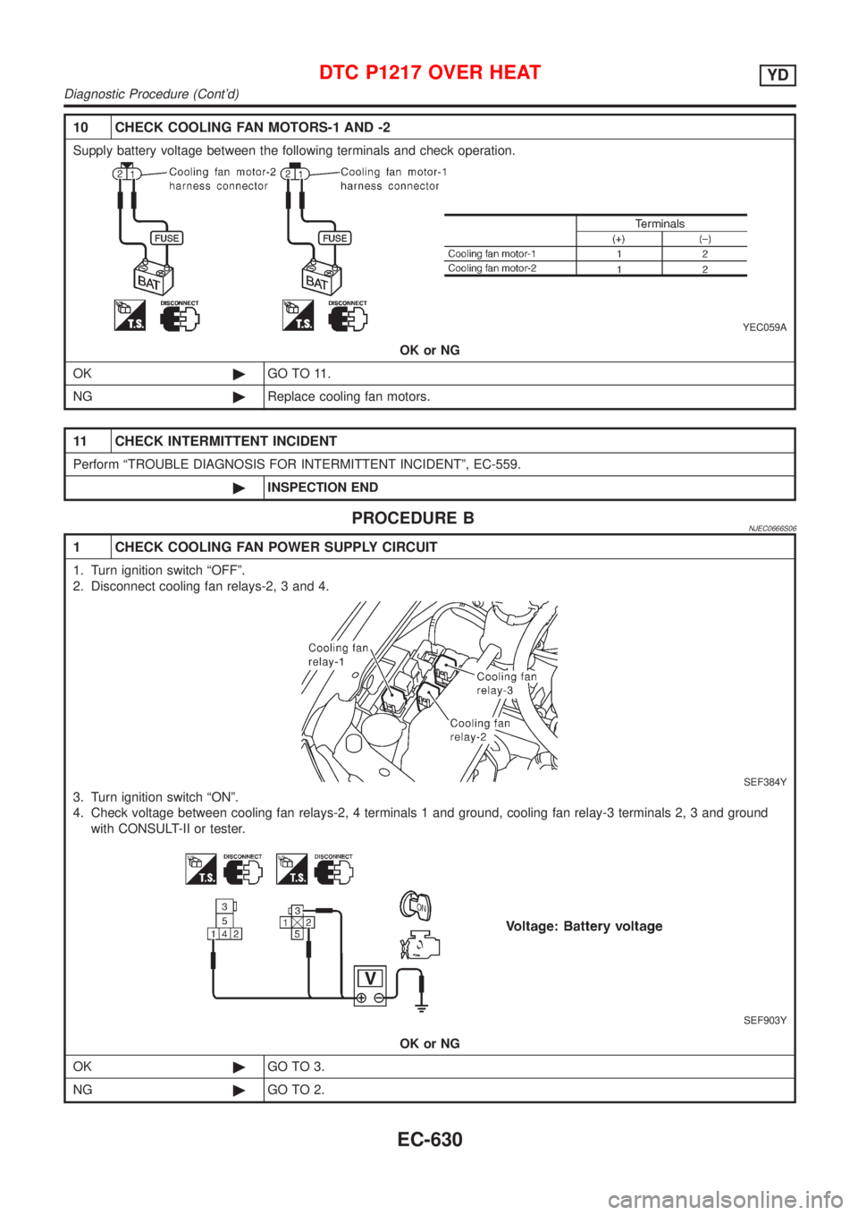
10 CHECK COOLING FAN MOTORS-1 AND -2
Supply battery voltage between the following terminals and check operation.
YEC059A
OK or NG
OK©GO TO 11.
NG©Replace cooling fan motors.
11 CHECK INTERMITTENT INCIDENT
Perform ªTROUBLE DIAGNOSIS FOR INTERMITTENT INCIDENTº, EC-559.
©INSPECTION END
PROCEDURE BNJEC0666S06
1 CHECK COOLING FAN POWER SUPPLY CIRCUIT
1. Turn ignition switch ªOFFº.
2. Disconnect cooling fan relays-2, 3 and 4.
SEF384Y
3. Turn ignition switch ªONº.
4. Check voltage between cooling fan relays-2, 4 terminals 1 and ground, cooling fan relay-3 terminals 2, 3 and ground
with CONSULT-II or tester.
SEF903Y
OK or NG
OK©GO TO 3.
NG©GO TO 2.
DTC P1217 OVER HEATYD
Diagnostic Procedure (Cont'd)
EC-630
Page 927 of 2493
2 DETECT MALFUNCTIONING PART
Check the following.
+30A fusible link
+10A fuse
+Harness for open or short between cooling fan relays-2, 3, 4 and fuse
+Harness for open or short between cooling fan relay-3 and fusible link
©Repair harness or connectors.
3 CHECK COOLING FAN GROUND CIRCUIT FOR OPEN AND SHORT
1. Turn ignition switch ªOFFº.
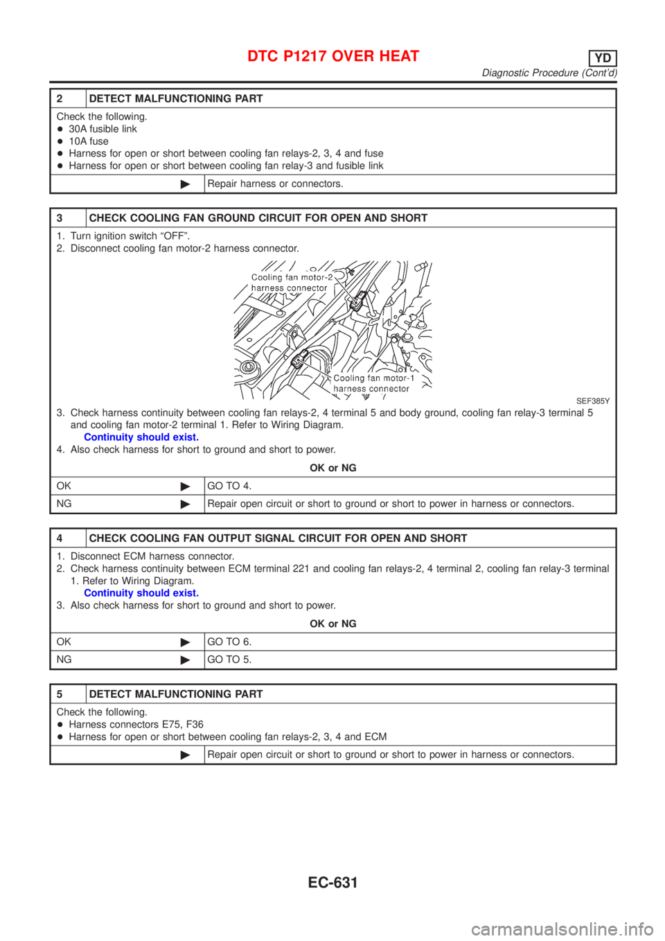
2. Disconnect cooling fan motor-2 harness connector.
SEF385Y
3. Check harness continuity between cooling fan relays-2, 4 terminal 5 and body ground, cooling fan relay-3 terminal 5
and cooling fan motor-2 terminal 1. Refer to Wiring Diagram.
Continuity should exist.
4. Also check harness for short to ground and short to power.
OK or NG
OK©GO TO 4.
NG©Repair open circuit or short to ground or short to power in harness or connectors.
4 CHECK COOLING FAN OUTPUT SIGNAL CIRCUIT FOR OPEN AND SHORT
1. Disconnect ECM harness connector.
2. Check harness continuity between ECM terminal 221 and cooling fan relays-2, 4 terminal 2, cooling fan relay-3 terminal
1. Refer to Wiring Diagram.
Continuity should exist.
3. Also check harness for short to ground and short to power.
OK or NG
OK©GO TO 6.
NG©GO TO 5.
5 DETECT MALFUNCTIONING PART
Check the following.
+Harness connectors E75, F36
+Harness for open or short between cooling fan relays-2, 3, 4 and ECM
©Repair open circuit or short to ground or short to power in harness or connectors.
DTC P1217 OVER HEATYD
Diagnostic Procedure (Cont'd)
EC-631
Page 928 of 2493
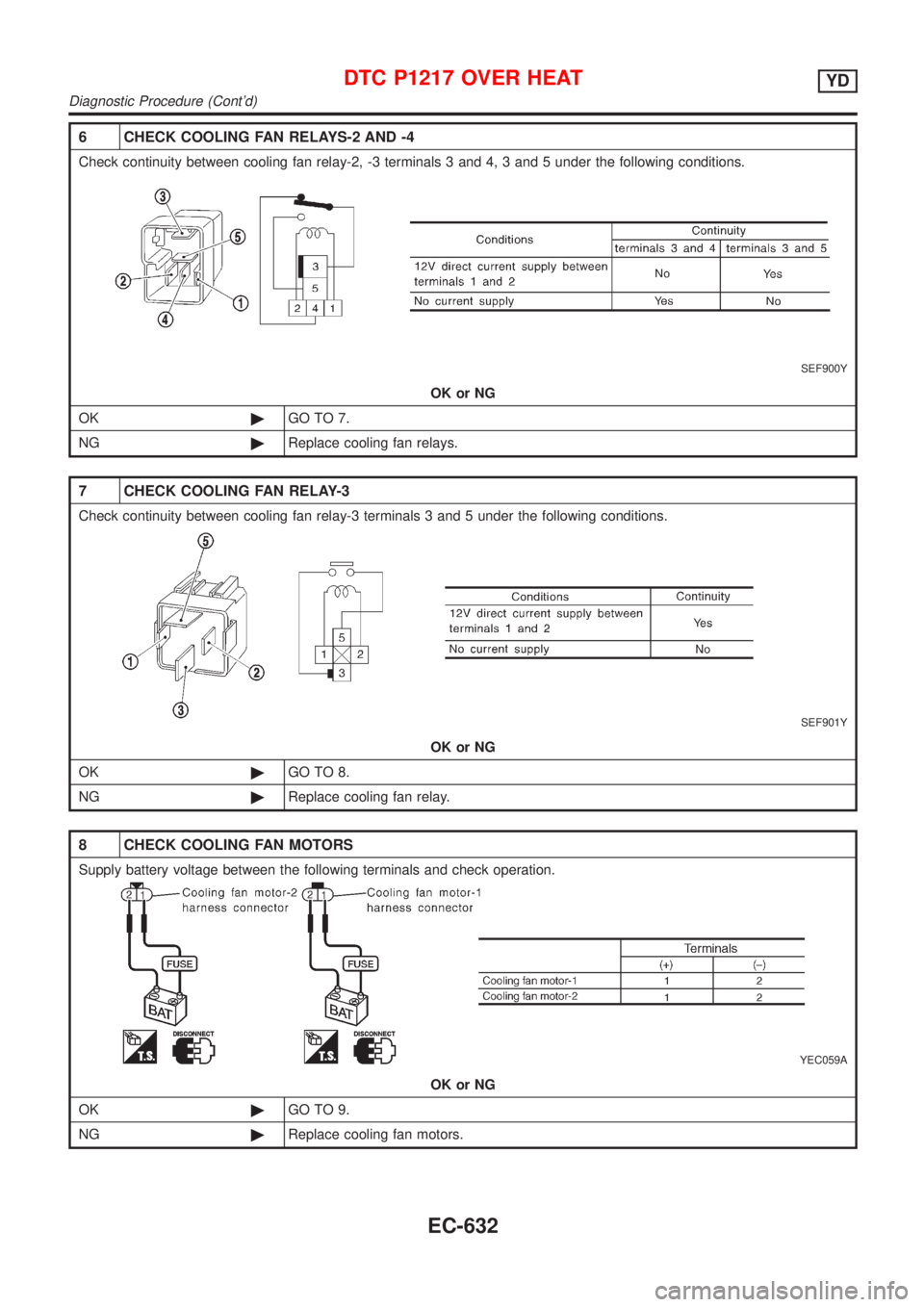
6 CHECK COOLING FAN RELAYS-2 AND -4
Check continuity between cooling fan relay-2, -3 terminals 3 and 4, 3 and 5 under the following conditions.
SEF900Y
OK or NG
OK©GO TO 7.
NG©Replace cooling fan relays.
7 CHECK COOLING FAN RELAY-3
Check continuity between cooling fan relay-3 terminals 3 and 5 under the following conditions.
SEF901Y
OK or NG
OK©GO TO 8.
NG©Replace cooling fan relay.
8 CHECK COOLING FAN MOTORS
Supply battery voltage between the following terminals and check operation.
YEC059A
OK or NG
OK©GO TO 9.
NG©Replace cooling fan motors.
DTC P1217 OVER HEATYD
Diagnostic Procedure (Cont'd)
EC-632