fuse NISSAN ALMERA N16 2001 Electronic Repair Manual
[x] Cancel search | Manufacturer: NISSAN, Model Year: 2001, Model line: ALMERA N16, Model: NISSAN ALMERA N16 2001Pages: 2493, PDF Size: 66.97 MB
Page 16 of 2493
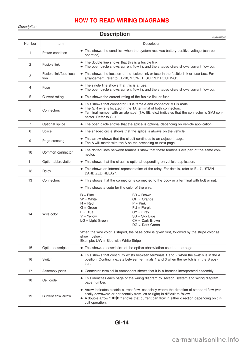
Description=NJGI0003S02
Number Item Description
1 Power condition+This shows the condition when the system receives battery positive voltage (can be
operated).
2 Fusible link+The double line shows that this is a fusible link.
+The open circle shows current flow in, and the shaded circle shows current flow out.
3Fusible link/fuse loca-
tion+This shows the location of the fusible link or fuse in the fusible link or fuse box. For
arrangement, refer to EL-10, ªPOWER SUPPLY ROUTINGº.
4 Fuse+The single line shows that this is a fuse.
+The open circle shows current flow in, and the shaded circle shows current flow out.
5 Current rating+This shows the current rating of the fusible link or fuse.
6 Connectors+This shows that connector E3 is female and connector M1 is male.
+The G/R wire is located in the 1A terminal of both connectors.
+Terminal number with an alphabet (1A, 5B, etc.) indicates that the connector is SMJ con-
nector. Refer to GI-19.
7 Optional splice+The open circle shows that the splice is optional depending on vehicle application.
8 Splice+The shaded circle shows that the splice is always on the vehicle.
9 Page crossing+This arrow shows that the circuit continues to an adjacent page.
+The A will match with the A on the preceding or next page.
10 Common connector+The dotted lines between terminals show that these terminals are part of the same con-
nector.
11 Option abbreviation+This shows that the circuit is optional depending on vehicle application.
12 Relay+This shows an internal representation of the relay. For details, refer to EL-7, ªSTAN-
DARDIZED RELAYº.
13 Connectors+This shows that the connector is connected to the body or a terminal with bolt or nut.
14 Wire color+This shows a code for the color of the wire.
B = Black
W = White
R = Red
G = Green
L = Blue
Y = Yellow
LG = Light GreenBR = Brown
OR = Orange
P = Pink
PU = Purple
GY = Gray
SB = Sky Blue
CH = Dark Brown
DG = Dark Green
When the wire color is striped, the base color is given first, followed by the stripe color as
shown below:
Example: L/W = Blue with White Stripe
15 Option description+This shows a description of the option abbreviation used on the page.
16 Switch+This shows that continuity exists between terminals 1 and 2 when the switch is in the A
position. Continuity exists between terminals 1 and 3 when the switch is in the B posi-
tion.
17 Assembly parts+Connector terminal in component shows that it is a harness incorporated assembly.
18 Cell code+This identifies each page of the wiring diagram by section, system and wiring diagram
page number.
19 Current flow arrow+Arrow indicates electric current flow, especially where the direction of standard flow (ver-
tically downward or horizontally from left to right) is difficult to follow.
+A double arrow ª
º shows that current can flow in either direction depending on cir-
cuit operation.
HOW TO READ WIRING DIAGRAMS
Description
GI-14
Page 17 of 2493
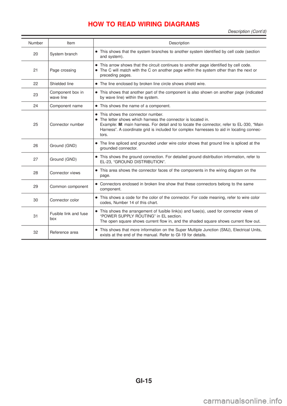
Number Item Description
20 System branch+This shows that the system branches to another system identified by cell code (section
and system).
21 Page crossing+This arrow shows that the circuit continues to another page identified by cell code.
+The C will match with the C on another page within the system other than the next or
preceding pages.
22 Shielded line+The line enclosed by broken line circle shows shield wire.
23Component box in
wave line+This shows that another part of the component is also shown on another page (indicated
by wave line) within the system.
24 Component name+This shows the name of a component.
25 Connector number+This shows the connector number.
+The letter shows which harness the connector is located in.
Example:M: main harness. For detail and to locate the connector, refer to EL-330, ªMain
Harnessº. A coordinate grid is included for complex harnesses to aid in locating connec-
tors.
26 Ground (GND)+The line spliced and grounded under wire color shows that ground line is spliced at the
grounded connector.
27 Ground (GND)+This shows the ground connection. For detailed ground distribution information, refer to
EL-23, ªGROUND DISTRIBUTIONº.
28 Connector views+This area shows the connector faces of the components in the wiring diagram on the
page.
29 Common component+Connectors enclosed in broken line show that these connectors belong to the same
component.
30 Connector color+This shows a code for the color of the connector. For code meaning, refer to wire color
codes, Number 14 of this chart.
31Fusible link and fuse
box+This shows the arrangement of fusible link(s) and fuse(s), used for connector views of
ªPOWER SUPPLY ROUTINGº in EL section.
The open square shows current flow in, and the shaded square shows current flow out.
32 Reference area+This shows that more information on the Super Multiple Junction (SMJ), Electrical Units,
exists at the end of the manual. Refer to GI-19 for details.
HOW TO READ WIRING DIAGRAMS
Description (Cont'd)
GI-15
Page 22 of 2493
manual.
Fuse block Ð Junction box (J/B)
Fuse block Ð Junction box (J/B) connector number is shown in the
Reference Area of the wiring diagram. For connector terminal and
fuse arrangement, refer to the ªFUSE BLOCK Ð Junction Box
(J/B)º electrical reference page at the end of the manual.
Fuse and fusible link box
For fuse arrangement in the fuse and fusible link box, refer to the
ªFUSE AND FUSIBLE LINK BOXº electrical reference page at the
end of the manual.
Electrical units
Electrical unit connector symbols are shown in the Connector Area
of the wiring diagram.
However, when there is not enough space to show the connector
terminal arrangement in the Connector Area of the wiring diagram,
the electrical unit connector number is shown in the Reference
Area of the wiring diagram. For electrical unit connector terminal
arrangement, refer to the ªELECTRICAL UNITSº electrical refer-
ence page at the end of the manual. Most of the electrical unit
connectors on this page are shown from the harness side of the
connector.
Joint connector
Joint connector symbols are shown in the connector area of the
wiring diagram. For connector internal wiring layout and joint con-
nector terminal arrangement, refer to the ªJOINT CONNECTOR
(J/C)º electrical reference page at the end of the manual.
HOW TO READ WIRING DIAGRAMS
Description (Cont'd)
GI-20
Page 27 of 2493
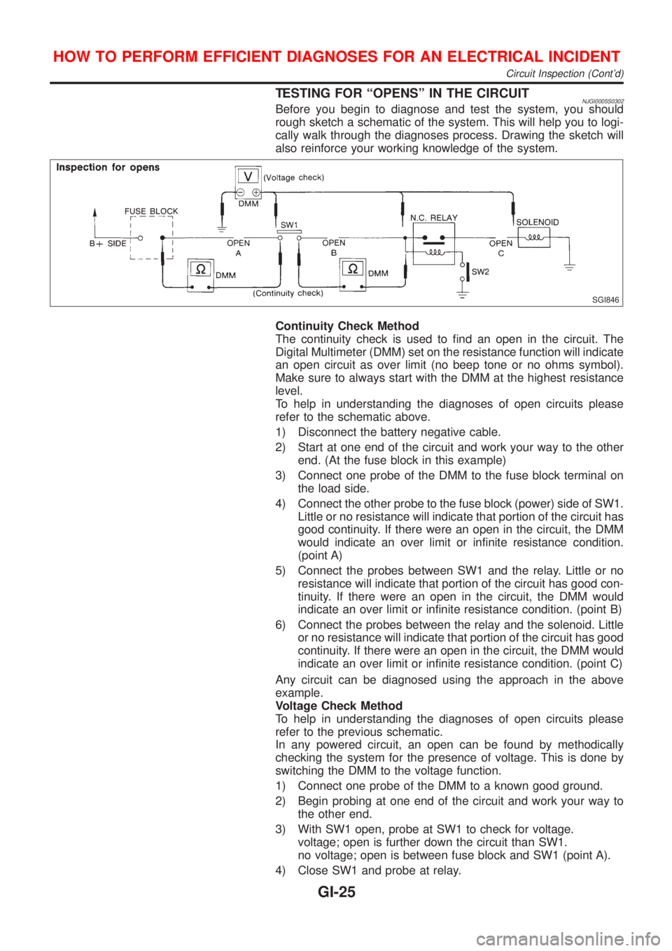
TESTING FOR ªOPENSº IN THE CIRCUITNJGI0005S0302Before you begin to diagnose and test the system, you should
rough sketch a schematic of the system. This will help you to logi-
cally walk through the diagnoses process. Drawing the sketch will
also reinforce your working knowledge of the system.
SGI846
Continuity Check Method
The continuity check is used to find an open in the circuit. The
Digital Multimeter (DMM) set on the resistance function will indicate
an open circuit as over limit (no beep tone or no ohms symbol).
Make sure to always start with the DMM at the highest resistance
level.
To help in understanding the diagnoses of open circuits please
refer to the schematic above.
1) Disconnect the battery negative cable.
2) Start at one end of the circuit and work your way to the other
end. (At the fuse block in this example)
3) Connect one probe of the DMM to the fuse block terminal on
the load side.
4) Connect the other probe to the fuse block (power) side of SW1.
Little or no resistance will indicate that portion of the circuit has
good continuity. If there were an open in the circuit, the DMM
would indicate an over limit or infinite resistance condition.
(point A)
5) Connect the probes between SW1 and the relay. Little or no
resistance will indicate that portion of the circuit has good con-
tinuity. If there were an open in the circuit, the DMM would
indicate an over limit or infinite resistance condition. (point B)
6) Connect the probes between the relay and the solenoid. Little
or no resistance will indicate that portion of the circuit has good
continuity. If there were an open in the circuit, the DMM would
indicate an over limit or infinite resistance condition. (point C)
Any circuit can be diagnosed using the approach in the above
example.
Voltage Check Method
To help in understanding the diagnoses of open circuits please
refer to the previous schematic.
In any powered circuit, an open can be found by methodically
checking the system for the presence of voltage. This is done by
switching the DMM to the voltage function.
1) Connect one probe of the DMM to a known good ground.
2) Begin probing at one end of the circuit and work your way to
the other end.
3) With SW1 open, probe at SW1 to check for voltage.
voltage; open is further down the circuit than SW1.
no voltage; open is between fuse block and SW1 (point A).
4) Close SW1 and probe at relay.
HOW TO PERFORM EFFICIENT DIAGNOSES FOR AN ELECTRICAL INCIDENT
Circuit Inspection (Cont'd)
GI-25
Page 28 of 2493
voltage; open is further down the circuit than the relay.
no voltage; open is between SW1 and relay (point B).
5) Close the relay and probe at the solenoid.
voltage; open is further down the circuit than the solenoid.
no voltage; open is between relay and solenoid (point C).
Any powered circuit can be diagnosed using the approach in the
above example.
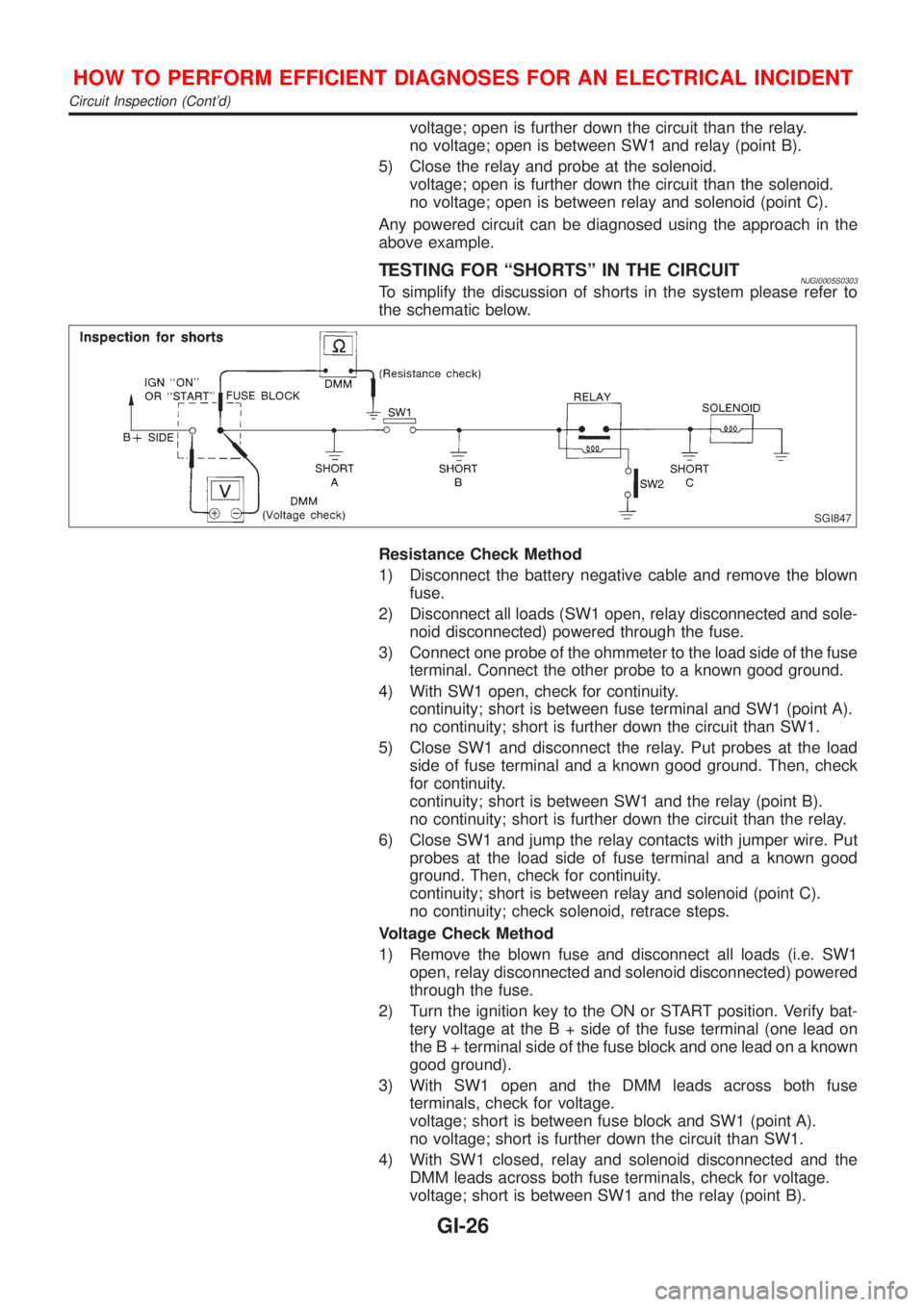
TESTING FOR ªSHORTSº IN THE CIRCUITNJGI0005S0303To simplify the discussion of shorts in the system please refer to
the schematic below.
SGI847
Resistance Check Method
1) Disconnect the battery negative cable and remove the blown
fuse.
2) Disconnect all loads (SW1 open, relay disconnected and sole-
noid disconnected) powered through the fuse.
3) Connect one probe of the ohmmeter to the load side of the fuse
terminal. Connect the other probe to a known good ground.
4) With SW1 open, check for continuity.
continuity; short is between fuse terminal and SW1 (point A).
no continuity; short is further down the circuit than SW1.
5) Close SW1 and disconnect the relay. Put probes at the load
side of fuse terminal and a known good ground. Then, check
for continuity.
continuity; short is between SW1 and the relay (point B).
no continuity; short is further down the circuit than the relay.
6) Close SW1 and jump the relay contacts with jumper wire. Put
probes at the load side of fuse terminal and a known good
ground. Then, check for continuity.
continuity; short is between relay and solenoid (point C).
no continuity; check solenoid, retrace steps.
Voltage Check Method
1) Remove the blown fuse and disconnect all loads (i.e. SW1
open, relay disconnected and solenoid disconnected) powered
through the fuse.
2) Turn the ignition key to the ON or START position. Verify bat-
tery voltage at the B + side of the fuse terminal (one lead on
the B + terminal side of the fuse block and one lead on a known
good ground).
3) With SW1 open and the DMM leads across both fuse
terminals, check for voltage.
voltage; short is between fuse block and SW1 (point A).
no voltage; short is further down the circuit than SW1.
4) With SW1 closed, relay and solenoid disconnected and the
DMM leads across both fuse terminals, check for voltage.
voltage; short is between SW1 and the relay (point B).
HOW TO PERFORM EFFICIENT DIAGNOSES FOR AN ELECTRICAL INCIDENT
Circuit Inspection (Cont'd)
GI-26
Page 29 of 2493
no voltage; short is further down the circuit than the relay.
5) With SW1 closed, relay contacts jumped with fused jumper
wire check for voltage.
voltage; short is down the circuit of the relay or between the
relay and the disconnected solenoid (point C).
no voltage; retrace steps and check power to fuse block.
GROUND INSPECTIONNJGI0005S0304Ground connections are very important to the proper operation of
electrical and electronic circuits. Ground connections are often
exposed to moisture, dirt and other corrosive elements. The corro-
sion (rust) can become an unwanted resistance. This unwanted
resistance can change the way a circuit works.
Electronically controlled circuits are very sensitive to proper
grounding. A loose or corroded ground can drastically affect an
electronically controlled circuit. A poor or corroded ground can eas-
ily affect the circuit. Even when the ground connection looks clean,
there can be a thin film of rust on the surface.
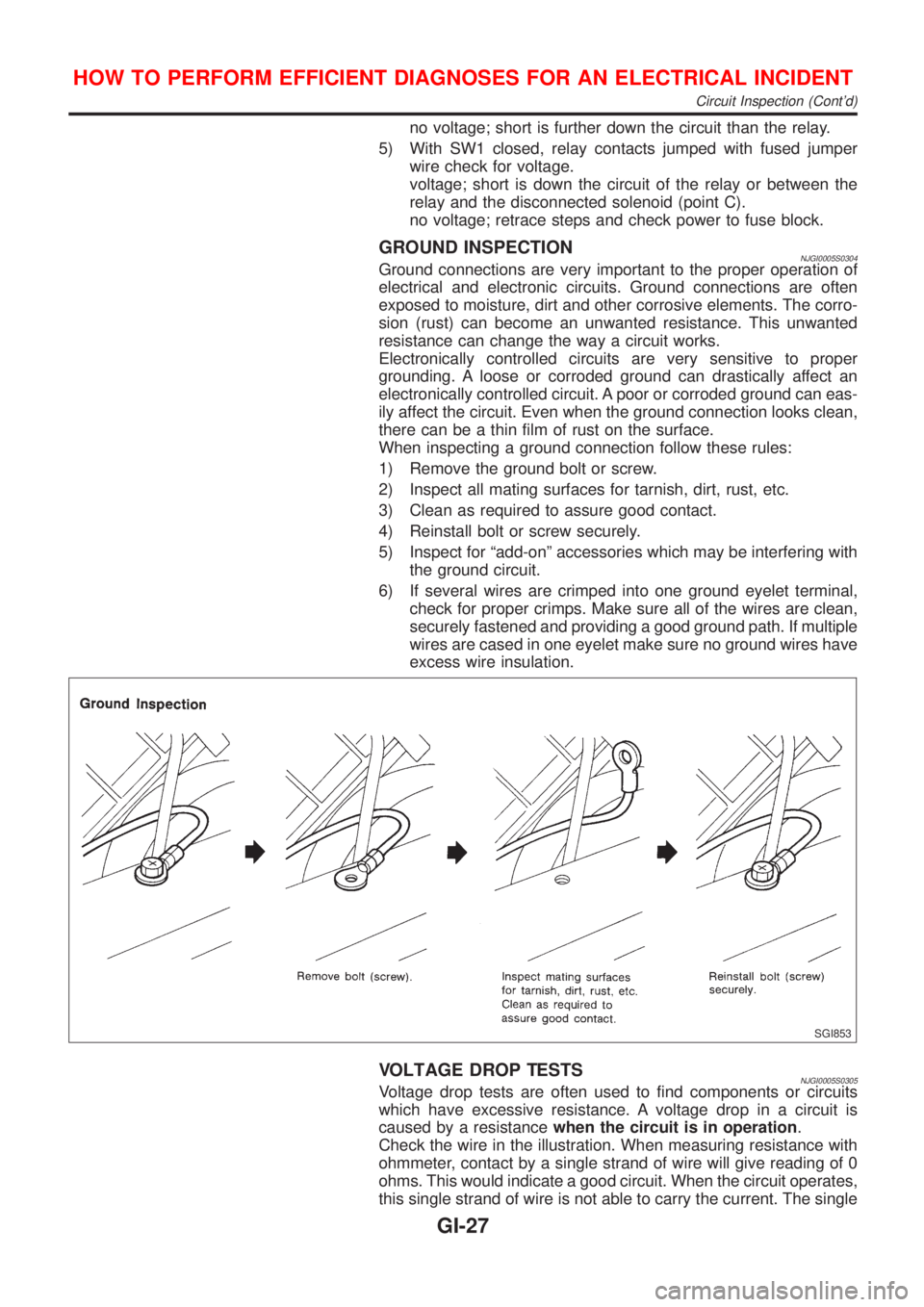
When inspecting a ground connection follow these rules:
1) Remove the ground bolt or screw.
2) Inspect all mating surfaces for tarnish, dirt, rust, etc.
3) Clean as required to assure good contact.
4) Reinstall bolt or screw securely.
5) Inspect for ªadd-onº accessories which may be interfering with
the ground circuit.
6) If several wires are crimped into one ground eyelet terminal,
check for proper crimps. Make sure all of the wires are clean,
securely fastened and providing a good ground path. If multiple
wires are cased in one eyelet make sure no ground wires have
excess wire insulation.
SGI853
VOLTAGE DROP TESTSNJGI0005S0305Voltage drop tests are often used to find components or circuits
which have excessive resistance. A voltage drop in a circuit is
caused by a resistancewhen the circuit is in operation.
Check the wire in the illustration. When measuring resistance with
ohmmeter, contact by a single strand of wire will give reading of 0
ohms. This would indicate a good circuit. When the circuit operates,
this single strand of wire is not able to carry the current. The single
HOW TO PERFORM EFFICIENT DIAGNOSES FOR AN ELECTRICAL INCIDENT
Circuit Inspection (Cont'd)
GI-27
Page 35 of 2493
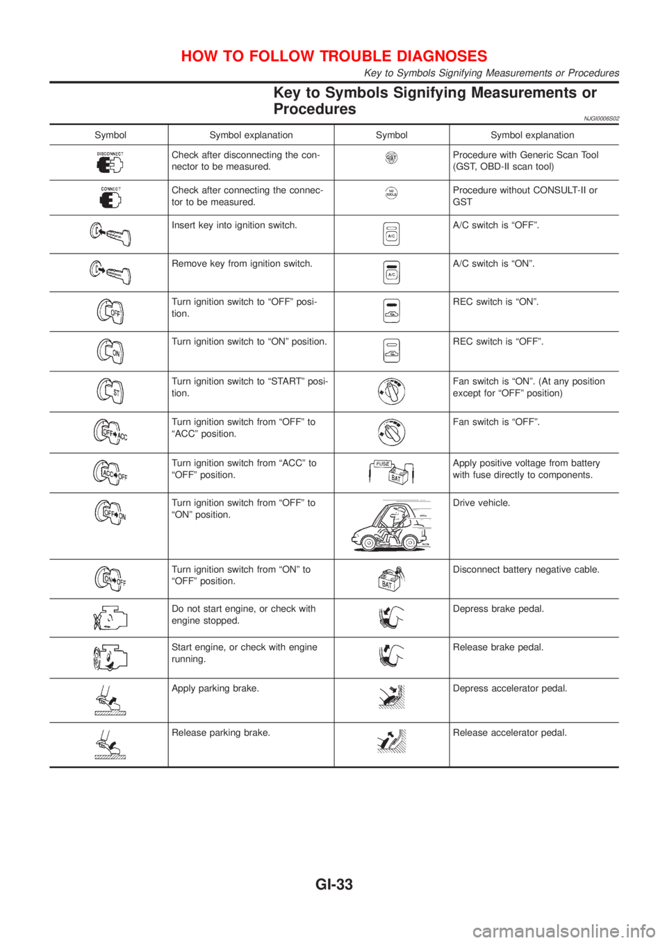
Key to Symbols Signifying Measurements or
Procedures
NJGI0006S02
Symbol Symbol explanation Symbol Symbol explanation
Check after disconnecting the con-
nector to be measured.Procedure with Generic Scan Tool
(GST, OBD-II scan tool)
Check after connecting the connec-
tor to be measured.Procedure without CONSULT-II or
GST
Insert key into ignition switch.A/C switch is ªOFFº.
Remove key from ignition switch.A/C switch is ªONº.
Turn ignition switch to ªOFFº posi-
tion.REC switch is ªONº.
Turn ignition switch to ªONº position.REC switch is ªOFFº.
Turn ignition switch to ªSTARTº posi-
tion.Fan switch is ªONº. (At any position
except for ªOFFº position)
Turn ignition switch from ªOFFº to
ªACCº position.Fan switch is ªOFFº.
Turn ignition switch from ªACCº to
ªOFFº position.Apply positive voltage from battery
with fuse directly to components.
Turn ignition switch from ªOFFº to
ªONº position.Drive vehicle.
Turn ignition switch from ªONº to
ªOFFº position.Disconnect battery negative cable.
Do not start engine, or check with
engine stopped.Depress brake pedal.
Start engine, or check with engine
running.Release brake pedal.
Apply parking brake.Depress accelerator pedal.
Release parking brake.Release accelerator pedal.
HOW TO FOLLOW TROUBLE DIAGNOSES
Key to Symbols Signifying Measurements or Procedures
GI-33
Page 58 of 2493
NJMA0036
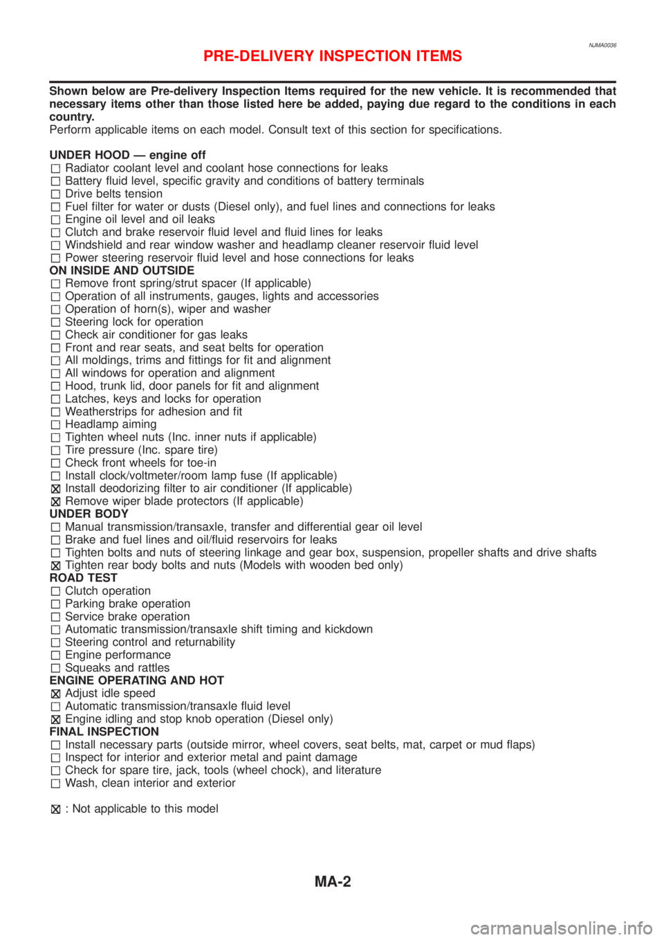
Shown below are Pre-delivery Inspection Items required for the new vehicle. It is recommended that
necessary items other than those listed here be added, paying due regard to the conditions in each
country.
Perform applicable items on each model. Consult text of this section for specifications.
UNDER HOOD Ð engine off
Radiator coolant level and coolant hose connections for leaks
Battery fluid level, specific gravity and conditions of battery terminals
Drive belts tension
Fuel filter for water or dusts (Diesel only), and fuel lines and connections for leaks
Engine oil level and oil leaks
Clutch and brake reservoir fluid level and fluid lines for leaks
Windshield and rear window washer and headlamp cleaner reservoir fluid level
Power steering reservoir fluid level and hose connections for leaks
ON INSIDE AND OUTSIDE
Remove front spring/strut spacer (If applicable)
Operation of all instruments, gauges, lights and accessories
Operation of horn(s), wiper and washer
Steering lock for operation
Check air conditioner for gas leaks
Front and rear seats, and seat belts for operation
All moldings, trims and fittings for fit and alignment
All windows for operation and alignment
Hood, trunk lid, door panels for fit and alignment
Latches, keys and locks for operation
Weatherstrips for adhesion and fit
Headlamp aiming
Tighten wheel nuts (Inc. inner nuts if applicable)
Tire pressure (Inc. spare tire)
Check front wheels for toe-in
Install clock/voltmeter/room lamp fuse (If applicable)
Install deodorizing filter to air conditioner (If applicable)
Remove wiper blade protectors (If applicable)
UNDER BODY
Manual transmission/transaxle, transfer and differential gear oil level
Brake and fuel lines and oil/fluid reservoirs for leaks
Tighten bolts and nuts of steering linkage and gear box, suspension, propeller shafts and drive shafts
Tighten rear body bolts and nuts (Models with wooden bed only)
ROAD TEST
Clutch operation
Parking brake operation
Service brake operation
Automatic transmission/transaxle shift timing and kickdown
Steering control and returnability
Engine performance
Squeaks and rattles
ENGINE OPERATING AND HOT
Adjust idle speed
Automatic transmission/transaxle fluid level
Engine idling and stop knob operation (Diesel only)
FINAL INSPECTION
Install necessary parts (outside mirror, wheel covers, seat belts, mat, carpet or mud flaps)
Inspect for interior and exterior metal and paint damage
Check for spare tire, jack, tools (wheel chock), and literature
Wash, clean interior and exterior
: Not applicable to this model
PRE-DELIVERY INSPECTION ITEMS
MA-2
Page 92 of 2493
NJEM0007
1. Warm up engine.
2. Turn ignition switch OFF.
3. Release fuel pressure.
Refer to EC-38, ªReleasing Fuel Pressureº.
4. Remove ignition coils.
5. Remove spark plugs.
+Clean area around plug with compressed air before removing
the spark plug.
SEM973E
AEM308
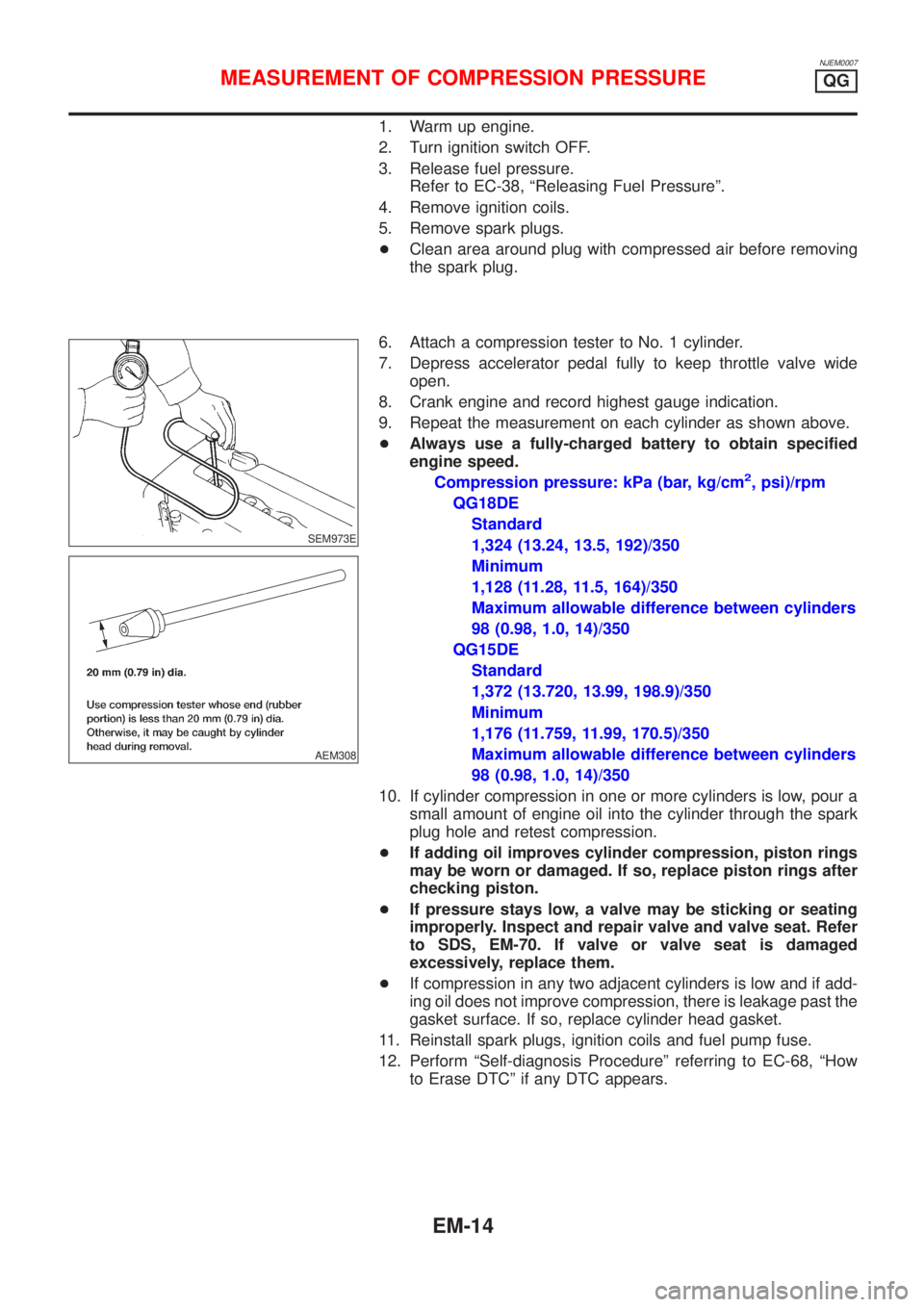
6. Attach a compression tester to No. 1 cylinder.
7. Depress accelerator pedal fully to keep throttle valve wide
open.
8. Crank engine and record highest gauge indication.
9. Repeat the measurement on each cylinder as shown above.
+Always use a fully-charged battery to obtain specified
engine speed.
Compression pressure: kPa (bar, kg/cm
2, psi)/rpm
QG18DE
Standard
1,324 (13.24, 13.5, 192)/350
Minimum
1,128 (11.28, 11.5, 164)/350
Maximum allowable difference between cylinders
98 (0.98, 1.0, 14)/350
QG15DE
Standard
1,372 (13.720, 13.99, 198.9)/350
Minimum
1,176 (11.759, 11.99, 170.5)/350
Maximum allowable difference between cylinders
98 (0.98, 1.0, 14)/350
10. If cylinder compression in one or more cylinders is low, pour a
small amount of engine oil into the cylinder through the spark
plug hole and retest compression.
+If adding oil improves cylinder compression, piston rings
may be worn or damaged. If so, replace piston rings after
checking piston.
+If pressure stays low, a valve may be sticking or seating
improperly. Inspect and repair valve and valve seat. Refer
to SDS, EM-70. If valve or valve seat is damaged
excessively, replace them.
+If compression in any two adjacent cylinders is low and if add-
ing oil does not improve compression, there is leakage past the
gasket surface. If so, replace cylinder head gasket.
11. Reinstall spark plugs, ignition coils and fuel pump fuse.
12. Perform ªSelf-diagnosis Procedureº referring to EC-68, ªHow
to Erase DTCº if any DTC appears.
MEASUREMENT OF COMPRESSION PRESSUREQG
EM-14
Page 160 of 2493
NJEM0053
JEM111G
1. Warm up engine.
2. Turn ignition switch OFF.
3. Using CONSULT-II, make sure no error codes are indicated for
self-diagnosis items. Refer to EC-492, ªTrouble Diagnosis Ð
INDEXº.
+Do not disconnect CONSULT-II until the end of this operation;
it will be used to check engine rpm and for error detection at
the end of this operation.
4. Disconnect the negative battery terminal.
5. To prevent fuel from being injected during inspection, remove
fuel injection pump fuse [ENG CONT2 (20A)] from fuse box on
the left side of engine compartment.
6. Remove glow plugs from all the cylinders.
+Before removal, clean the surrounding area to prevent
entry of any foreign materials into the engine.
+Carefully remove glow plugs to prevent any damage or
breakage.
+Handle with care to avoid applying any shock to glow
plugs.
SEM112G
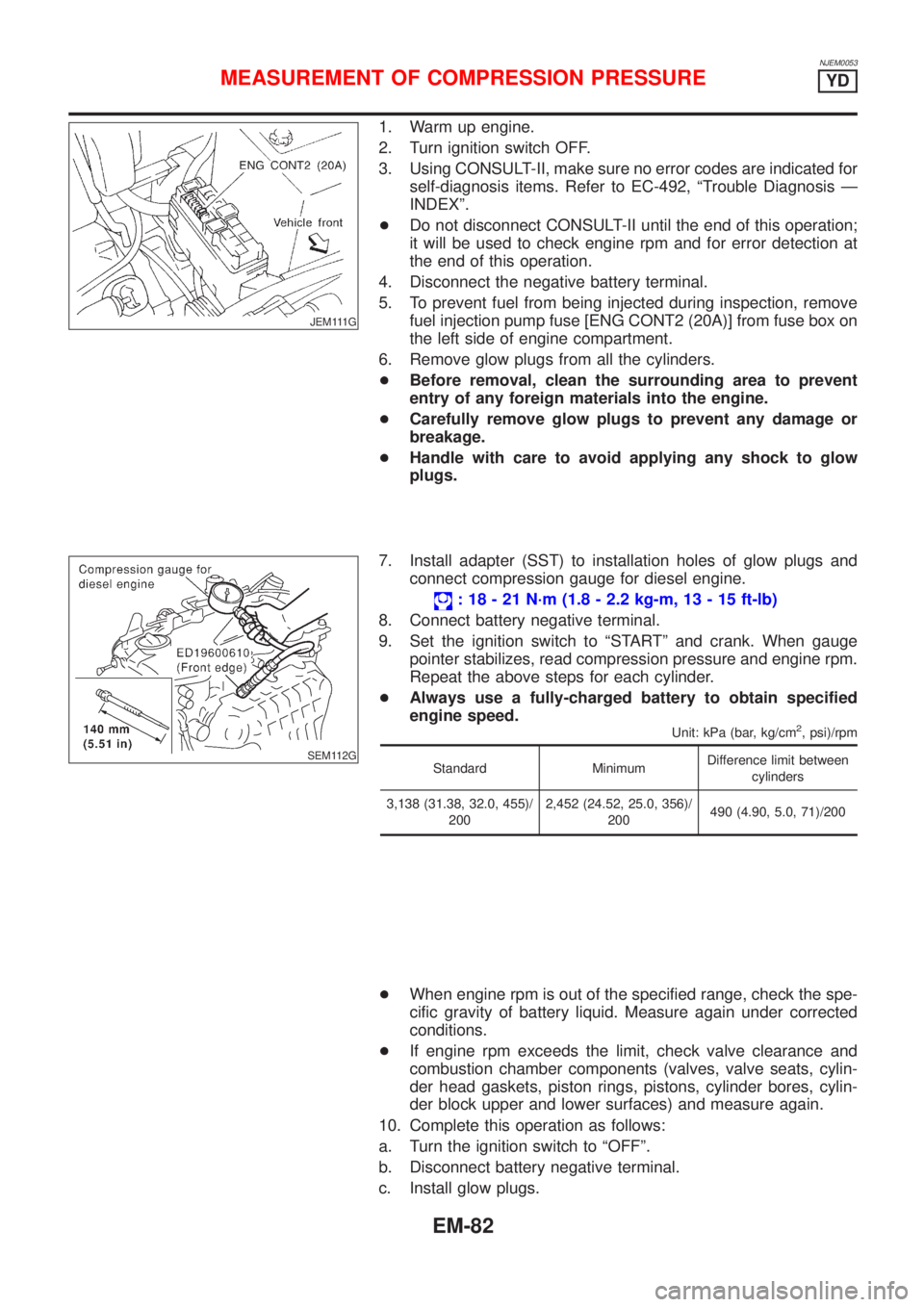
7. Install adapter (SST) to installation holes of glow plugs and
connect compression gauge for diesel engine.
: 18 - 21 N´m (1.8 - 2.2 kg-m, 13 - 15 ft-lb)
8. Connect battery negative terminal.
9. Set the ignition switch to ªSTARTº and crank. When gauge
pointer stabilizes, read compression pressure and engine rpm.
Repeat the above steps for each cylinder.
+Always use a fully-charged battery to obtain specified
engine speed.
Unit: kPa (bar, kg/cm2, psi)/rpm
Standard MinimumDifference limit between
cylinders
3,138 (31.38, 32.0, 455)/
2002,452 (24.52, 25.0, 356)/
200490 (4.90, 5.0, 71)/200
+When engine rpm is out of the specified range, check the spe-
cific gravity of battery liquid. Measure again under corrected
conditions.
+If engine rpm exceeds the limit, check valve clearance and
combustion chamber components (valves, valve seats, cylin-
der head gaskets, piston rings, pistons, cylinder bores, cylin-
der block upper and lower surfaces) and measure again.
10. Complete this operation as follows:
a. Turn the ignition switch to ªOFFº.
b. Disconnect battery negative terminal.
c. Install glow plugs.
MEASUREMENT OF COMPRESSION PRESSUREYD
EM-82