ESP NISSAN ALMERA N16 2003 Electronic User Guide
[x] Cancel search | Manufacturer: NISSAN, Model Year: 2003, Model line: ALMERA N16, Model: NISSAN ALMERA N16 2003Pages: 3189, PDF Size: 54.76 MB
Page 251 of 3189
Removal and InstallationNJEM0071CAUTION:
When installing bearings, pistons, or other sliding parts,
lubricate contacting surfaces with new engine oil.
Place removed parts such as bearings and bearing caps
in their proper order and direction.
When installing connecting rod nuts, and main bearing
cap bolts, apply new engine oil to threads and seating
surfaces.
Do not allow any magnetic materials to contact the signal
plate of flywheel.
Do not remove the signal plate at back.
Do not place the signal plate side facing under.
Handle with care so as not to damage the signal plate
[especially four places on protrusions for signal of crank
position sensor (TDC sensor)].
DisassemblyNJEM0072PISTON AND CRANKSHAFTNJEM0072S011. Remove engine. Refer to “ENGINE ASSEMBLY”, “Removal
and Installation”, EM-63.
2. Place engine on a work stand.
a. Remove flywheel.
Hold ring gear with ring gear stopper (KV10105630,
KV10105610). Then, loosen securing bolts with TORX socket
(size: Q8 E20, Commercial Service Tool) and remove them.
As an alternative method, hold the crankshaft pulley with a
pulley holder (SST) to remove the flywheel.
JEM192G
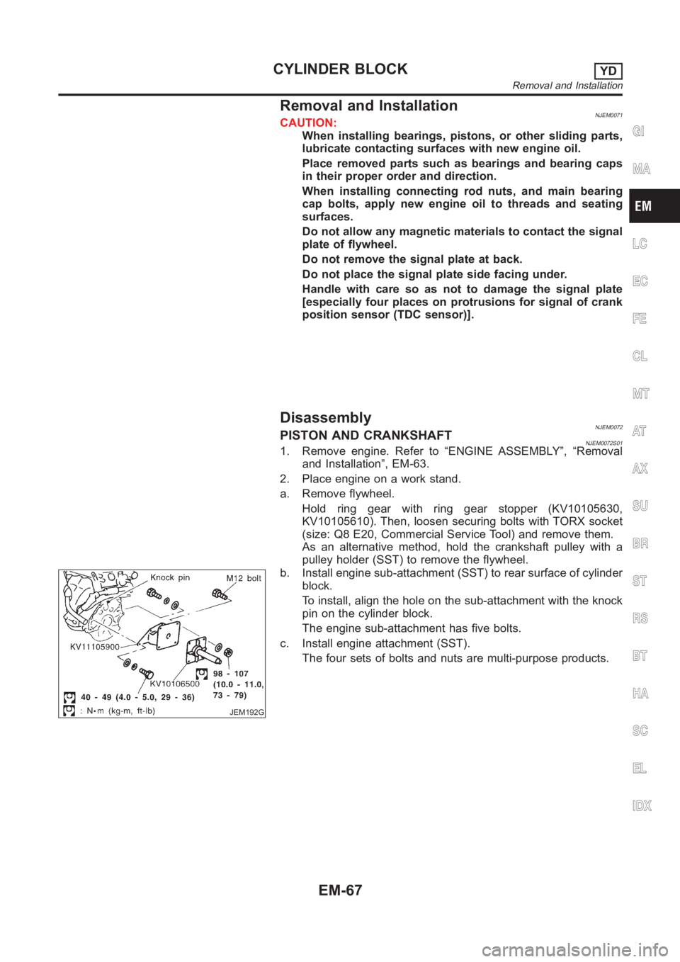
b. Install engine sub-attachment (SST) to rear surface of cylinder
block.
To install, align the hole on the sub-attachment with the knock
pin on the cylinder block.
The engine sub-attachment has five bolts.
c. Install engine attachment (SST).
The four sets of bolts and nuts are multi-purpose products.
GI
MA
LC
EC
FE
CL
MT
AT
AX
SU
BR
ST
RS
BT
HA
SC
EL
IDX
CYLINDER BLOCKYD
Removal and Installation
EM-67
Page 264 of 3189
JEM220G
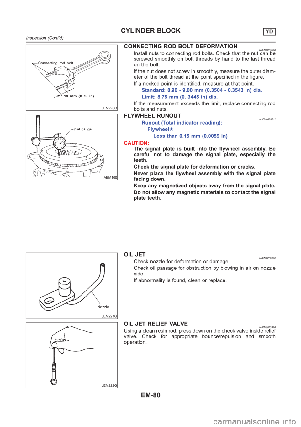
CONNECTING ROD BOLT DEFORMATIONNJEM0073S18Install nuts to connecting rod bolts. Check that the nut can be
screwed smoothly on bolt threads by hand to the last thread
on the bolt.
If the nut does not screw in smoothly, measure the outer diam-
eter of the bolt thread at the point specified in the figure.
If a necked point is identified, measure at that point.
Standard: 8.90 - 9.00 mm (0.3504 - 0.3543 in) dia.
Limit: 8.75 mm (0. 3445 in) dia.
If the measurement exceeds the limit, replace connecting rod
bolts and nuts.
AEM100
FLYWHEEL RUNOUTNJEM0073S11Runout (Total indicator reading):
Flywheel★
Less than 0.15 mm (0.0059 in)
CAUTION:
The signal plate is built into the flywheel assembly. Be
careful not to damage the signal plate, especially the
teeth.
Check the signal plate for deformation or cracks.
Never place the flywheel assembly with the signal plate
facing down.
Keep any magnetized objects away from the signal plate.
Do not allow any magnetic materials to contact the signal
plate teeth.
JEM221G
OIL JETNJEM0073S19Check nozzle for deformation or damage.
Check oil passage for obstruction by blowing in air on nozzle
side.
If abnormality is found, clean or replace.
JEM222G
OIL JET RELIEF VALVENJEM0073S20Using a clean resin rod, press down on the check valve inside relief
valve. Check for appropriate bounce/repulsion and smooth
operation.
CYLINDER BLOCKYD
Inspection (Cont’d)
EM-80
Page 345 of 3189
![NISSAN ALMERA N16 2003 Electronic User Guide PRECAUTIONS
EC-15
[QG (WITH EURO-OBD)]
C
D
E
F
G
H
I
J
K
L
MA
EC
PRECAUTIONSPFP:00001
Precautions for Supplemental Restraint System (SRS) “AIR BAG” and “SEAT
BELT PRE-TENSIONER”
EBS00K2V
The](/img/5/57350/w960_57350-344.png "NISSAN ALMERA N16 2003 Electronic User Guide PRECAUTIONS
EC-15
[QG (WITH EURO-OBD)]
C
D
E
F
G
H
I
J
K
L
MA
EC
PRECAUTIONSPFP:00001
Precautions for Supplemental Restraint System (SRS) “AIR BAG” and “SEAT
BELT PRE-TENSIONER”
EBS00K2V
The")
PRECAUTIONS
EC-15
[QG (WITH EURO-OBD)]
C
D
E
F
G
H
I
J
K
L
MA
EC
PRECAUTIONSPFP:00001
Precautions for Supplemental Restraint System (SRS) “AIR BAG” and “SEAT
BELT PRE-TENSIONER”
EBS00K2V
The Supplemental Restraint System such as “AIR BAG” and “SEAT BELT PRE-TENSIONER”, used along
with a front seat belt, helps to reduce the risk or severity of injury to the driver and front passenger for certain
types of collision. Information necessary to service the system safely is included in the SRS and SB section of
this Service Manual.
WARNING:
●To avoid rendering the SRS inoperative, which could increase the risk of personal injury or death
in the event of a collision which would result in air bag inflation, all maintenance must be per-
formed by an authorized NISSAN/INFINITI dealer.
●Improper maintenance, including incorrect removal and installation of the SRS, can lead to per-
sonal injury caused by unintentional activation of the system. For removal of Spiral Cable and Air
Bag Module, see the SRS section.
●Do not use electrical test equipment on any circuit related to the SRS unless instructed to in this
Service Manual. SRS wiring harnesses can be identified by yellow and/or orange harness connec-
tors.
On Board Diagnostic (OBD) System of Engine and A/TEBS00K2W
The ECM has an on board diagnostic system. It will light up the malfunction indicator (MI) to warn the driver of
a malfunction causing emission deterioration.
CAUTION:
●Be sure to turn the ignition switch OFF and disconnect the battery ground cable before any repair
or inspection work. The open/short circuit of related switches, sensors, solenoid valves, etc. will
cause the MI to light up.
●Be sure to connect and lock the connectors securely after work. A loose (unlocked) connector will
cause the MI to light up due to the open circuit. (Be sure the connector is free from water, grease,
dirt, bent terminals, etc.)
●Certain systems and components, especially those related to OBD, may use a new style slide-
locking type harness connector. For description and how to disconnect, refer to EL-7.
●Be sure to route and secure the harnesses properly after work. The interference of the harness
with a bracket, etc. may cause the MI to light up due to the short circuit.
●Be sure to connect rubber tubes properly after work. A misconnected or disconnected rubber tube
may cause the MI to light up due to the malfunction of the fuel injection system, etc.
●Be sure to erase the unnecessary malfunction information (repairs completed) from the ECM and
TCM (Transmission control module) before returning the vehicle to the customer.
PrecautionEBS00K2X
●Always use a 12 volt battery as power source.
●Do not attempt to disconnect battery cables while engine is
running.
●Before connecting or disconnecting the ECM harness con-
nector, turn ignition switch OFF and disconnect battery
ground cable. Failure to do so may damage the ECM
because battery voltage is applied to ECM even if ignition
switch is turned off.
●Before removing parts, turn ignition switch OFF and then
disconnect battery ground cable.
SEF289H
Page 372 of 3189
![NISSAN ALMERA N16 2003 Electronic User Guide EC-42
[QG (WITH EURO-OBD)]
ON BOARD DIAGNOSTIC (OBD) SYSTEM
SRT Item
The table below shows required self-diagnostic items to set the SRT to “CMPLT”.
*1: If completion of several SRTs is required,](/img/5/57350/w960_57350-371.png "NISSAN ALMERA N16 2003 Electronic User Guide EC-42
[QG (WITH EURO-OBD)]
ON BOARD DIAGNOSTIC (OBD) SYSTEM
SRT Item
The table below shows required self-diagnostic items to set the SRT to “CMPLT”.
*1: If completion of several SRTs is required,")
EC-42
[QG (WITH EURO-OBD)]
ON BOARD DIAGNOSTIC (OBD) SYSTEM
SRT Item
The table below shows required self-diagnostic items to set the SRT to “CMPLT”.
*1: If completion of several SRTs is required, perform driving patterns (DTC confirmation procedure), one by one based on the priority for
models with CONSULT-II.
SRT Set Timing
SRT is set as “CMPLT” after self-diagnosis has been performed one or more times. Completion of SRT is
done regardless of whether the result is OK or NG. The set timing is different between OK and NG results and
is shown in the table below.
OK: Self-diagnosis is carried out and the result is OK.
NG: Self-diagnosis is carried out and the result is NG.
—: Self-diagnosis is not carried out.
When all SRT related self-diagnoses showed OK results in a single cycle (Ignition OFF-ON-OFF), the SRT will
indicate “CMPLT”. → Case 1 above
When all SRT related self-diagnoses showed OK results through several different cycles, the SRT will indicate
“CMPLT” at the time the respective self-diagnoses have at least one OK result. → Case 2 above
SRT item
(CONSULT-II indi-
cation)Performance
Priority
*1Required self-diagnostic items to set the SRT to “CMPLT”
Corresponding DTC
No.
CATALYST 2 Three way catalyst function P0420
HO2S 1 Heated oxygen sensor 1 P0132
Heated oxygen sensor 1 P0133
Heated oxygen sensor 1 P0134
Heated oxygen sensor 1 P1143
Heated oxygen sensor 1 P1144
Heated oxygen sensor 2 P0138
Heated oxygen sensor 2 P0139
Heated oxygen sensor 2 P1146
Heated oxygen sensor 2 P1147
HO2S HTR 1 Heated oxygen sensor 1 heater P0031, P0032
Heated oxygen sensor 2 heater P0037, P0038
Self-diagnosis resultExample
DiagnosisIgnition cycle
← ON → OFF ← ON → OFF ← ON → OFF ← ON →
All OK Case 1 P0400 OK (1) — (1) OK (2) — (2)
P0402 OK (1) — (1) — (1) OK (2)
P1402 OK (1) OK (2) — (2) — (2)
SRT of EGR “CMPLT” “CMPLT” “CMPLT” “CMPLT”
Case 2 P0400 OK (1) — (1) — (1) — (1)
P0402 — (0) — (0) OK (1) — (1)
P1402 OK (1) OK (2) — (2) — (2)
SRT of EGR “INCMP” “INCMP” “CMPLT” “CMPLT”
NG exists Case 3 P0400 OK OK — —
P0402 — — — —
P1402 NG — NGNG
(Consecutive
NG)
(1st trip)
DTC1st trip DTC — 1st trip DTCDTC
(= MI “ON”)
SRT of EGR “INCMP” “INCMP” “INCMP” “CMPLT”
Page 373 of 3189
![NISSAN ALMERA N16 2003 Electronic User Guide ON BOARD DIAGNOSTIC (OBD) SYSTEM
EC-43
[QG (WITH EURO-OBD)]
C
D
E
F
G
H
I
J
K
L
MA
EC
If one or more SRT related self-diagnoses showed NG results in 2 consecutive cycles, the SRT will also indi-
cate](/img/5/57350/w960_57350-372.png "NISSAN ALMERA N16 2003 Electronic User Guide ON BOARD DIAGNOSTIC (OBD) SYSTEM
EC-43
[QG (WITH EURO-OBD)]
C
D
E
F
G
H
I
J
K
L
MA
EC
If one or more SRT related self-diagnoses showed NG results in 2 consecutive cycles, the SRT will also indi-
cate")
ON BOARD DIAGNOSTIC (OBD) SYSTEM
EC-43
[QG (WITH EURO-OBD)]
C
D
E
F
G
H
I
J
K
L
MA
EC
If one or more SRT related self-diagnoses showed NG results in 2 consecutive cycles, the SRT will also indi-
cate “CMPLT”. → Case 3 above
The table above shows that the minimum number of cycles for setting SRT as “INCMP” is one (1) for each
self-diagnosis (Case 1 & 2) or two (2) for one of self-diagnoses (Case 3). However, in preparation for the state
emissions inspection, it is unnecessary for each self-diagnosis to be executed twice (Case 3) for the following
reasons:
●The SRT will indicate “CMPLT” at the time the respective self-diagnoses have one (1) OK result.
●The emissions inspection requires “CMPLT” of the SRT only with OK self-diagnosis results.
●When, during SRT driving pattern, 1st trip DTC (NG) is detected prior to “CMPLT” of SRT, the self-diagno-
sis memory must be erased from ECM after repair.
●If the 1st trip DTC is erased, all the SRT will indicate “INCMP”.
NOTE:
SRT can be set as “CMPLT” together with the DTC(s). Therefore, DTC check must always be carried out
prior to the state emission inspection even though the SRT indicates “CMPLT”.
SRT Service Procedure
If a vehicle has failed the state emissions inspection due to one or more SRT items indicating “INCMP”, review
the flowchart diagnostic sequence on the next page.
Page 375 of 3189
![NISSAN ALMERA N16 2003 Electronic User Guide ON BOARD DIAGNOSTIC (OBD) SYSTEM
EC-45
[QG (WITH EURO-OBD)]
C
D
E
F
G
H
I
J
K
L
MA
EC
How to Set SRT Code
To set all SRT codes, self-diagnosis for the items indicated above must be performed one or mo](/img/5/57350/w960_57350-374.png "NISSAN ALMERA N16 2003 Electronic User Guide ON BOARD DIAGNOSTIC (OBD) SYSTEM
EC-45
[QG (WITH EURO-OBD)]
C
D
E
F
G
H
I
J
K
L
MA
EC
How to Set SRT Code
To set all SRT codes, self-diagnosis for the items indicated above must be performed one or mo")
ON BOARD DIAGNOSTIC (OBD) SYSTEM
EC-45
[QG (WITH EURO-OBD)]
C
D
E
F
G
H
I
J
K
L
MA
EC
How to Set SRT Code
To set all SRT codes, self-diagnosis for the items indicated above must be performed one or more times. Each
diagnosis may require a long period of actual driving under various conditions.
WITH CONSULT-II
Perform corresponding DTC Confirmation Procedure one by one based on “Performance Priority” in the table
on EC-42, "
SRT Item" .
WITHOUT CONSULT-II
The most efficient driving pattern in which SRT codes can be properly set is explained on the next page. The
driving pattern should be performed one or more times to set all SRT codes.
Page 388 of 3189
![NISSAN ALMERA N16 2003 Electronic User Guide EC-58
[QG (WITH EURO-OBD)]
TROUBLE DIAGNOSIS
TROUBLE DIAGNOSIS
PFP:00004
Trouble Diagnosis IntroductionEBS00K3L
INTRODUCTION
The engine has an ECM to control major systems such as fuel con-
trol, ign](/img/5/57350/w960_57350-387.png "NISSAN ALMERA N16 2003 Electronic User Guide EC-58
[QG (WITH EURO-OBD)]
TROUBLE DIAGNOSIS
TROUBLE DIAGNOSIS
PFP:00004
Trouble Diagnosis IntroductionEBS00K3L
INTRODUCTION
The engine has an ECM to control major systems such as fuel con-
trol, ign")
EC-58
[QG (WITH EURO-OBD)]
TROUBLE DIAGNOSIS
TROUBLE DIAGNOSIS
PFP:00004
Trouble Diagnosis IntroductionEBS00K3L
INTRODUCTION
The engine has an ECM to control major systems such as fuel con-
trol, ignition control, idle air control system, etc. The ECM accepts
input signals from sensors and instantly drives actuators. It is essen-
tial that both input and output signals are proper and stable. At the
same time, it is important that there are no malfunctions such as vac-
uum leaks, fouled spark plugs, or other malfunctions with the engine.
It is much more difficult to diagnose a incident that occurs intermit-
tently rather than continuously. Most intermittent incidents are
caused by poor electric connections or improper wiring. In this case,
careful checking of suspected circuits may help prevent the replace-
ment of good parts.
A visual check only may not find the cause of the incidents. A road
test with CONSULT-II (or GST) or a circuit tester connected should
be performed. Follow the “Work Flow” on EC-59
.
Before undertaking actual checks, take a few minutes to talk with a
customer who approaches with a driveability complaint. The cus-
tomer can supply good information about such incidents, especially
intermittent ones. Find out what symptoms are present and under
what conditions they occur. A “Diagnostic Worksheet” like the exam-
ple on EC-62
should be used.
Start your diagnosis by looking for “conventional” malfunctions first.
This will help troubleshoot driveability malfunctions on an electroni-
cally controlled engine vehicle.
MEF036D
SEF233G
SEF234G
Page 395 of 3189
![NISSAN ALMERA N16 2003 Electronic User Guide TROUBLE DIAGNOSIS
EC-65
[QG (WITH EURO-OBD)]
C
D
E
F
G
H
I
J
K
L
MA
EC
Basic InspectionEBS00K3O
1.INSPECTION START
1. Check service records for any recent repairs that may indicate a related malfuncti](/img/5/57350/w960_57350-394.png "NISSAN ALMERA N16 2003 Electronic User Guide TROUBLE DIAGNOSIS
EC-65
[QG (WITH EURO-OBD)]
C
D
E
F
G
H
I
J
K
L
MA
EC
Basic InspectionEBS00K3O
1.INSPECTION START
1. Check service records for any recent repairs that may indicate a related malfuncti")
TROUBLE DIAGNOSIS
EC-65
[QG (WITH EURO-OBD)]
C
D
E
F
G
H
I
J
K
L
MA
EC
Basic InspectionEBS00K3O
1.INSPECTION START
1. Check service records for any recent repairs that may indicate a related malfunction, or a current need for
scheduled maintenance.
2. Open engine hood and check the following:
–Harness connectors for improper connections
–Wiring harness for improper connections, pinches and cut
–Vacuum hoses for splits, kinks and improper connections
–Hoses and ducts for leaks
–Air cleaner clogging
–Gasket
3. Confirm that electrical or mechanical loads are not applied.
–Headlamp switch is OFF.
–Air conditioner switch is OFF.
–Rear window defogger switch is OFF.
–Steering wheel is in the straight-ahead position, etc.
4. Start engine and warm it up until engine coolant temperature
indicator points the middle of gauge.
Ensure engine stays below 1,000 rpm.
5. Run engine at about 2,000 rpm for about 2 minutes under no-
load.
6. Make sure that no DTC is displayed with CONSULT-II or GST.
OK or NG
OK >> GO TO 3.
NG >> GO TO 2.
2.REPAIR OR REPLACE
Repair or replace components as necessary according to corresponding “Diagnostic Procedure”.
>> GO TO 3.
SEF983U
SEF976U
SEF977U
Page 426 of 3189
![NISSAN ALMERA N16 2003 Electronic User Guide EC-96
[QG (WITH EURO-OBD)]
TROUBLE DIAGNOSIS
DTC Work Support Mode
REAL TIME DIAGNOSIS IN DATA MONITOR MODE (RECORDING VEHICLE DATA)
Description
CONSULT-II has two kinds of triggers and they can be se](/img/5/57350/w960_57350-425.png "NISSAN ALMERA N16 2003 Electronic User Guide EC-96
[QG (WITH EURO-OBD)]
TROUBLE DIAGNOSIS
DTC Work Support Mode
REAL TIME DIAGNOSIS IN DATA MONITOR MODE (RECORDING VEHICLE DATA)
Description
CONSULT-II has two kinds of triggers and they can be se")
EC-96
[QG (WITH EURO-OBD)]
TROUBLE DIAGNOSIS
DTC Work Support Mode
REAL TIME DIAGNOSIS IN DATA MONITOR MODE (RECORDING VEHICLE DATA)
Description
CONSULT-II has two kinds of triggers and they can be selected by touching “SETTING” in “DATA MONITOR”
mode.
1. “AUTO TRIG” (Automatic trigger):
●The malfunction will be identified on the CONSULT-II screen
in real time.
In other words, DTC/1st trip DTC and malfunction item will be
displayed if the malfunction is detected by ECM.
At the moment a malfunction is detected by ECM, “MONI-
TOR” in “DATA MONITOR” screen is changed to “Recording
Data ... xx%” as shown at right, and the data after the mal-
function detection is recorded. Then when the percentage
reached 100%, “REAL-TIME DIAG” screen is displayed. If
“STOP” is touched on the screen during “Recording Data ...
xx%”, “REAL-TIME DIAG” screen is also displayed.
The recording time after the malfunction detection and the
recording speed can be changed by “TRIGGER POINT” and
“Recording Speed”. Refer to CONSULT-II OPERATION MAN-
UAL.
2. “MANU TRIG” (Manual trigger):
●DTC/1st trip DTC and malfunction item will not be displayed
automatically on CONSULT-II screen even though a malfunc-
tion is detected by ECM.
DATA MONITOR can be performed continuously even though
a malfunction is detected.
Test mode Test item Condition Reference page
HO2S1HO2S1 (B1) P0133
Refer to corresponding
trouble diagnosis for
DTC.EC-155
HO2S1 (B1) P0134EC-165
HO2S1 (B1) P1143EC-296
HO2S1 (B1) P1144EC-302
H02S2HO2S2 (B1) P0139EC-178HO2S2 (B1) P1146EC-308
HO2S2 (B1) P1147EC-316
SEF705Y
SEF707X
Page 427 of 3189
![NISSAN ALMERA N16 2003 Electronic User Guide TROUBLE DIAGNOSIS
EC-97
[QG (WITH EURO-OBD)]
C
D
E
F
G
H
I
J
K
L
MA
EC
Operation
1. “AUTO TRIG”
●While trying to detect the DTC/1st trip DTC by performing the “DTC Confirmation Procedure”,](/img/5/57350/w960_57350-426.png "NISSAN ALMERA N16 2003 Electronic User Guide TROUBLE DIAGNOSIS
EC-97
[QG (WITH EURO-OBD)]
C
D
E
F
G
H
I
J
K
L
MA
EC
Operation
1. “AUTO TRIG”
●While trying to detect the DTC/1st trip DTC by performing the “DTC Confirmation Procedure”,")
TROUBLE DIAGNOSIS
EC-97
[QG (WITH EURO-OBD)]
C
D
E
F
G
H
I
J
K
L
MA
EC
Operation
1. “AUTO TRIG”
●While trying to detect the DTC/1st trip DTC by performing the “DTC Confirmation Procedure”, be sure
to select to “DATA MONITOR (AUTO TRIG)” mode. You can confirm the malfunction at the moment it is
detected.
●While narrowing down the possible causes, CONSULT-II should be set in “DATA MONITOR (AUTO
TRIG)” mode, especially in case the incident is intermittent.
When you are inspecting the circuit by gently shaking (or twisting) the suspicious connectors, compo-
nents and harness in the “DTC Confirmation Procedure”, the moment a malfunction is found the DTC/
1st trip DTC will be displayed. (Refer to “Incident Simulation Tests” in GI-23.)
2. “MANU TRIG”
●If the malfunction is displayed as soon as “DATA MONITOR” is selected, reset CONSULT-II to “MANU
TRIG”. By selecting “MANU TRIG” you can monitor and store the data. The data can be utilized for fur-
ther diagnosis, such as a comparison with the value for the normal operating condition.
Generic Scan Tool (GST) FunctionEBS00K3V
DESCRIPTION
Generic Scan Tool (OBDII scan tool) complying with ISO 15031-4
has 8 different functions explained below.
ISO9141 is used as the protocol.
The name “GST” or “Generic Scan Tool” is used in this service man-
ual.
PBIB0197E
SEF139P