ESP NISSAN ALMERA N16 2003 Electronic Repair Manual
[x] Cancel search | Manufacturer: NISSAN, Model Year: 2003, Model line: ALMERA N16, Model: NISSAN ALMERA N16 2003Pages: 3189, PDF Size: 54.76 MB
Page 2 of 3189
FOREWORD
This manual contains maintenance and repair procedures for NISSAN
ALMERA, model N16 series.
In order to assure your safety and the efficient functioning of the vehicle,
this manual should be read thoroughly. It is especially important that the
PRECAUTIONS in the GI section be completely understood before starting
any repair task.
All information in this manual is based on the latest product information
at the time of publication. The right is reserved to make changes in speci-
fications and methods at any time without notice.
IMPORTANT SAFETY NOTICE
The proper performance of service is essential for both the safety of the
technician and the efficient functioning of the vehicle.
The service methods in this Service Manual are described in such a man-
ner that the service may be performed safely and accurately.
Service varies with the procedures used, the skills of the technician and the
tools and parts available. Accordingly, anyone using service procedures,
tools or parts which are not specifically recommended by NISSAN must
first completely satisfy himself that neither his safety nor the vehicle’s
safety will be jeopardized by the service method selected.
NISSAN EUROPE S.A.S.
Service Engineering Section
Paris, France
Page 6 of 3189
The security indicator is located on the combi meter. The indicator
blinks when the ignition switch is in “OFF” or “ACC” position.
Therefore, NATS warns outsiders that the vehicle is equipped with
the anti-theft system.
When NATS detects trouble, the security indicator lamp lights
up while ignition switch is in “ON” position.
This lighting up indicates that the anti-theft is not functioning,
so prompt service is required.
When servicing NATS (trouble diagnoses, system initialization
and additional registration of other NATS ignition key IDs),
CONSULT-II hardware and CONSULT-II NATS software is
necessary.
Regarding the procedures of NATS initialization and NATS
ignition key ID registration, refer to CONSULT-II operation
manual, NATS.
Therefore, CONSULT-II NATS software (program card and
operation manual) must be kept strictly confidential to main-
tain the integrity of the anti-theft function.
When servicing NATS (trouble diagnoses, system initialization
and additional registration of other NATS ignition key IDs), it
may be necessary to re-register original key identification.
Therefore, be sure to receive all keys from vehicle owner. A
maximum of five key IDs can be registered into NATS.
When failing to start the engine first time using the key of
NATS, start as follows.
a) Leave the ignition key in “ON” position for approximately 5
seconds.
b) Turn ignition key to “OFF” or “LOCK” position and wait approxi-
mately 5 seconds.
c) Repeat step 1 and 2 again.
d) Restart the engine while keeping the key separate from any
others on key-chain.
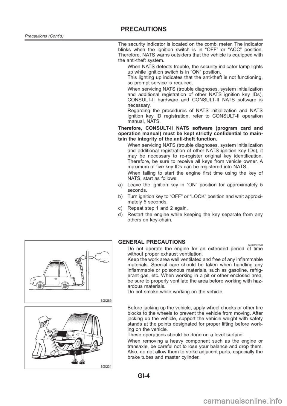
SGI285
GENERAL PRECAUTIONSNJGI0001S03Do not operate the engine for an extended period of time
without proper exhaust ventilation.
Keep the work area well ventilated and free of any inflammable
materials. Special care should be taken when handling any
inflammable or poisonous materials, such as gasoline, refrig-
erant gas, etc. When working in a pit or other enclosed area,
be sure to properly ventilate the area before working with haz-
ardous materials.
Do not smoke while working on the vehicle.
SGI231
Before jacking up the vehicle, apply wheel chocks or other tire
blocks to the wheels to prevent the vehicle from moving. After
jacking up the vehicle, support the vehicle weight with safety
stands at the points designated for proper lifting before work-
ing on the vehicle.
These operations should be done on a level surface.
When removing a heavy component such as the engine or
transaxle, be careful not to lose your balance and drop them.
Also, do not allow them to strike adjacent parts, especially the
brake tubes and master cylinder.
PRECAUTIONS
Precautions (Cont’d)
GI-4
Page 16 of 3189
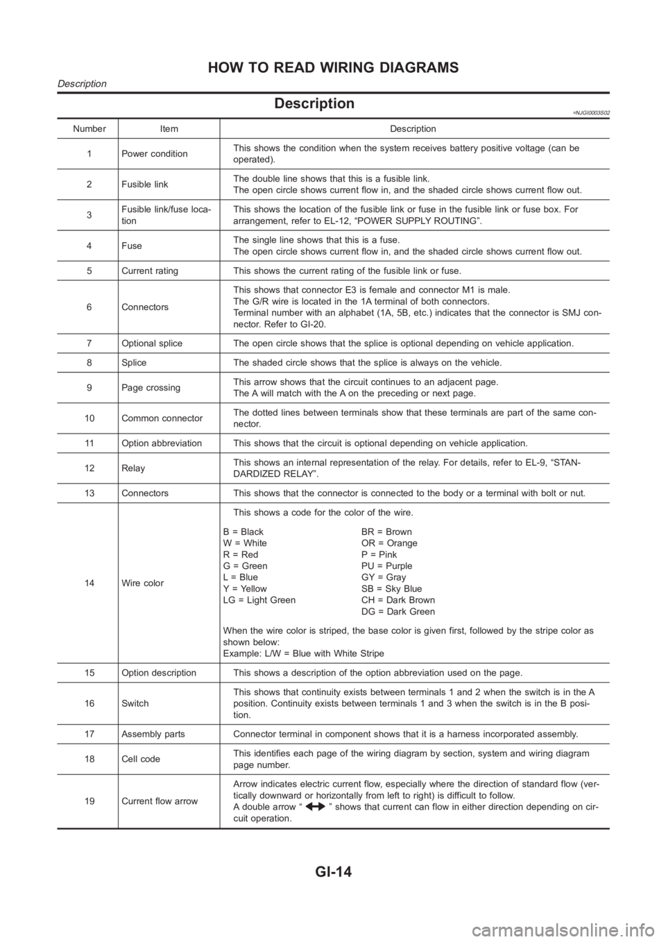
Description=NJGI0003S02
Number Item Description
1 Power conditionThis shows the condition when the system receives battery positive voltage (can be
operated).
2 Fusible linkThe double line shows that this is a fusible link.
The open circle shows current flow in, and the shaded circle shows current flow out.
3Fusible link/fuse loca-
tionThis shows the location of the fusible link or fuse in the fusible link or fusebox.For
arrangement, refer to EL-12, “POWER SUPPLY ROUTING”.
4FuseThe single line shows that this is a fuse.
The open circle shows current flow in, and the shaded circle shows current flow out.
5 Current rating This shows the current rating of the fusible link or fuse.
6 ConnectorsThis shows that connector E3 is female and connector M1 is male.
The G/R wire is located in the 1A terminal of both connectors.
Terminal number with an alphabet (1A, 5B, etc.) indicates that the connector is SMJ con-
nector. Refer to GI-20.
7 Optional splice The open circle shows that the splice is optional depending on vehicle application.
8 Splice The shaded circle shows that the splice is always on the vehicle.
9 Page crossingThis arrow shows that the circuit continues to an adjacent page.
The A will match with the A on the preceding or next page.
10 Common connectorThe dotted lines between terminals show that these terminals are part of thesamecon-
nector.
11 Option abbreviation This shows that the circuit is optional depending on vehicle application.
12 RelayThis shows an internal representation of the relay. For details, refer to EL-9, “STAN-
DARDIZED RELAY”.
13 Connectors This shows that the connector is connected to the body or a terminal with bolt or nut.
14 Wire colorThis shows a code for the color of the wire.
B=Black
W = White
R = Red
G = Green
L = Blue
Y = Yellow
LG = Light GreenBR = Brown
OR = Orange
P = Pink
PU = Purple
GY = Gray
SB = Sky Blue
CH = Dark Brown
DG=DarkGreen
When the wire color is striped, the base color is given first, followed by the stripe color as
shown below:
Example: L/W = Blue with White Stripe
15 Option description This shows a description of the option abbreviationused on the page.
16 SwitchThis shows that continuity exists between terminals 1 and 2 when the switchis in the A
position. Continuity exists between terminals 1 and 3 when the switch is inthe B posi-
tion.
17 Assembly parts Connector terminal in component shows that it is a harness incorporated assembly.
18 Cell codeThis identifies each page of the wiring diagram by section, system and wiring diagram
page number.
19 Current flow arrowArrow indicates electric current flow, especially where the direction ofstandard flow (ver-
tically downward or horizontally from left to right) is difficult to follow.
A double arrow “
” shows that current can flow in either direction depending on cir-
cuit operation.
HOW TO READ WIRING DIAGRAMS
Description
GI-14
Page 18 of 3189
SGI364
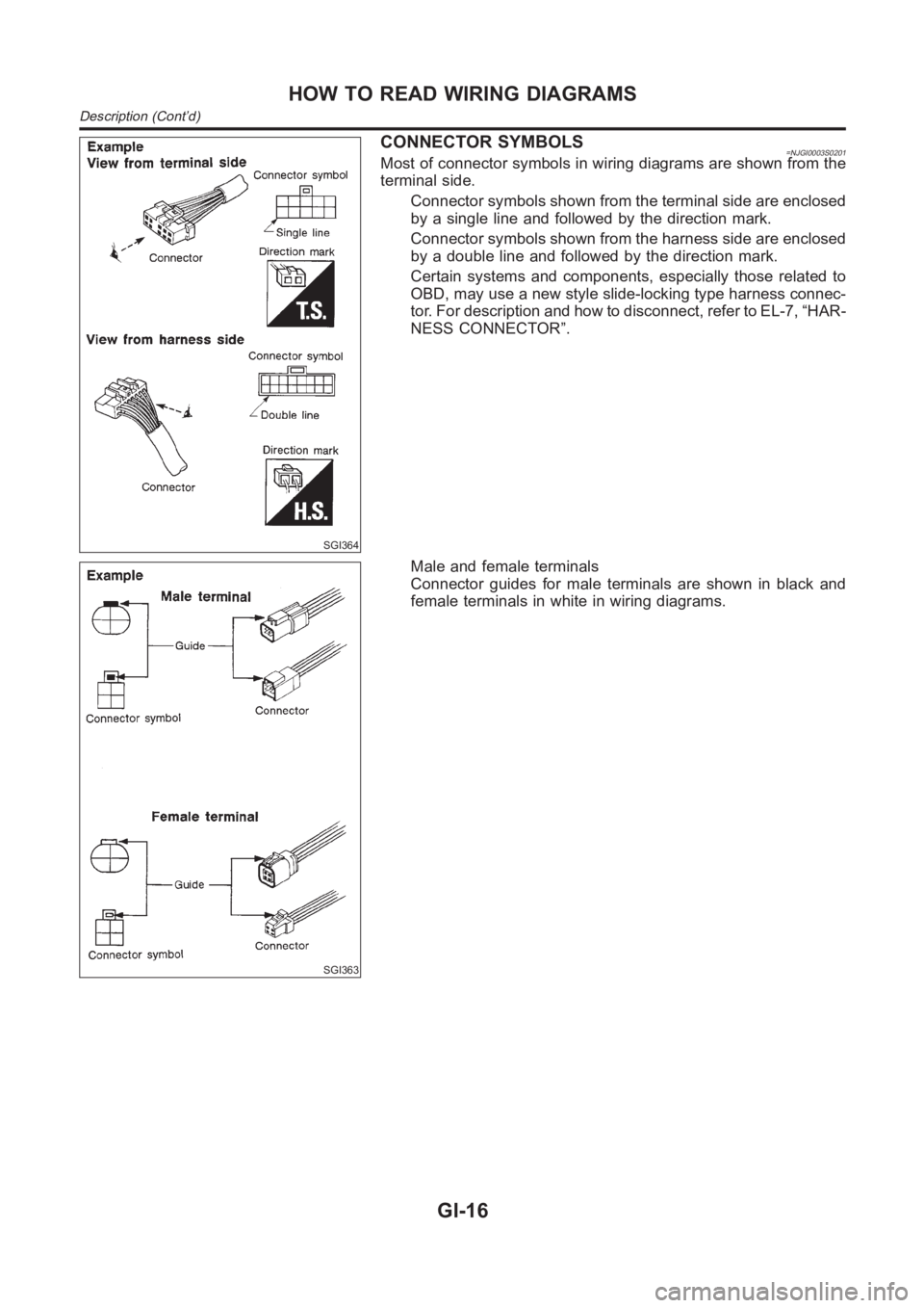
CONNECTOR SYMBOLS=NJGI0003S0201Most of connector symbols in wiring diagrams are shown from the
terminal side.
Connector symbols shown from the terminal side are enclosed
by a single line and followed by the direction mark.
Connector symbols shown from the harness side are enclosed
by a double line and followed by the direction mark.
Certain systems and components, especially those related to
OBD, may use a new style slide-locking type harness connec-
tor. For description and how to disconnect, refer to EL-7, “HAR-
NESS CONNECTOR”.
SGI363
Male and female terminals
Connector guides for male terminals are shown in black and
female terminals in white in wiring diagrams.
HOW TO READ WIRING DIAGRAMS
Description (Cont’d)
GI-16
Page 130 of 3189
![NISSAN ALMERA N16 2003 Electronic Repair Manual EM-52
[QG]
TIMING CHAIN
2. Install front oil seal to front cover.
●Install it so that identification letters on oil seal will face toward
front side of the engine.
●Using an oil seal drift (commer NISSAN ALMERA N16 2003 Electronic Repair Manual EM-52
[QG]
TIMING CHAIN
2. Install front oil seal to front cover.
●Install it so that identification letters on oil seal will face toward
front side of the engine.
●Using an oil seal drift (commer](/img/5/57350/w960_57350-129.png)
EM-52
[QG]
TIMING CHAIN
2. Install front oil seal to front cover.
●Install it so that identification letters on oil seal will face toward
front side of the engine.
●Using an oil seal drift (commercial service tool), press oil seal
in until it is flush with end surface of mounting position.
●Make sure that oil seal outer circumference is free from dam-
age and burr.
3. Install front cover with the following procedure:
a. Install O-ring to cylinder block.
b. Using a flat-bladed screwdriver, apply a continuous bead of liq-
uid gasket to contact surface between cylinder head gasket
lower surface and cylinder block (2 locations shown in figure).
Use Genuine Liquid Gasket or equivalent.
c. Apply a continuous bead of liquid gasket to back surface of front
cover (location shown in figure).
CAUTION:
●Do not apply liquid gasket to groove A shown in figure.
●Especially for locations indicated by * mark in figure,
strictly observe application range of liquid gasket.
d. Apply liquid gasket to top surface of front cover lightly and
evenly.
Use Genuine Liquid Gasket or equivalent.
e. Install O-ring to back surface of front cover.
f. With socket of oil pump inner rotor placed on crankshaft top sur-
face (clearance between front cover top surface and cylinder
head gasket lower surface is secured), move front cover close to
cylinder block. (Right side in figure)
g. Lift front cover at an angle and install it to mounting position so
that front cover will come in contact with both cylinder head gas-
ket lower surface and cylinder block front surface at the same
time. (Right side in figure)
CAUTION:
●During work, be sure not to damage cylinder head gas-
ket.
●When installing, avoid discontinuous bead of liquid gas-
ket caused by allowing it to adhere to an unnecessary area.
PBIC0530E
PBIC0561E
PBIC0562E
PBIC0563E
Page 135 of 3189
![NISSAN ALMERA N16 2003 Electronic Repair Manual CYLINDER HEAD
EM-57
[QG]
C
D
E
F
G
H
I
J
K
L
MA
EM
CYLINDER HEADPFP:11041
On-Vehicle ServiceEBS00LQH
CHECKING COMPRESSION PRESSURE
1. Warm up engine thoroughly. Then, stop it.
2. Release fuel pressu NISSAN ALMERA N16 2003 Electronic Repair Manual CYLINDER HEAD
EM-57
[QG]
C
D
E
F
G
H
I
J
K
L
MA
EM
CYLINDER HEADPFP:11041
On-Vehicle ServiceEBS00LQH
CHECKING COMPRESSION PRESSURE
1. Warm up engine thoroughly. Then, stop it.
2. Release fuel pressu](/img/5/57350/w960_57350-134.png)
CYLINDER HEAD
EM-57
[QG]
C
D
E
F
G
H
I
J
K
L
MA
EM
CYLINDER HEADPFP:11041
On-Vehicle ServiceEBS00LQH
CHECKING COMPRESSION PRESSURE
1. Warm up engine thoroughly. Then, stop it.
2. Release fuel pressure. Refer to EC-34, "
FUEL PRESSURE RELEASE" (WITH EURO-OBD), EC-427,
"FUEL PRESSURE RELEASE" (WITHOUT EURO-OBD).
3. Remove ignition coil and spark plug from each cylinder.
Refer to IGNITION COIL EM-24, "
Removal and Installation" and SPARK PLUG EM-25, "Removal and
Installation" .
4. Connect engine tachometer (not required in use of CONSULT-II).
5. Disconnect fuel injector harness connector so that no fuel is injected.
6. Install compression tester with adapter onto spark plug hole.
●Use compression gauge whose picking up end inserted to spark
plug hole is smaller than 20 mm (0.79 in) in diameter. Otherwise,
it may be caught by cylinder head during removal.
7. With accelerator pedal fully depressed, turn ignition switch to
“START” for cranking. When the gauge pointer stabilizes, read
the compression pressure and engine rpm. Perform these steps
to check each cylinder.
Compression pressure
[kPa (bar, kg/cm2 , psi)/rpm]
CAUTION:
Always use a fully changed battery to obtain specified engine speed.
●If the engine speed is out of specified range, check battery liquid for proper gravity. Check engine speed
again with normal battery gravity.
●If compression pressure is below minimum value, check valve clearances and parts associated with com-
bustion chamber (Valve, valve seat, piston, piston ring, cylinder bore, cylinder head, cylinder head gas-
ket). After the checking, measure compression pressure again.
●If some cylinders have low compression pressure, pour small amount of engine oil into the spark plug hole
of the cylinder to re-check it for compression.
–If the added engine oil improves the compression, the piston rings may be worn out or damaged. Check
the piston rings and replace if necessary.
–If the compression pressure remains at low level despite the addition of engine oil, the valves may be mal-
functioning. Check the valves for damage. Replace the valve or valve seat accordingly.
●If two adjacent cylinders have respectively low compression pressure and their compression remains low
even after the addition of engine oil, the gaskets are leaking. In such a case, replace the cylinder head
gaskets.
KBIA1402E
Engine type QG15DE QG18DE
Standard1,372 (13.72, 13.99,
198.9)1,324 (13.24, 13.5, 192)
Limit 1,176 (11.76, 12.0, 170.5) 1,128 (11.28, 11.5, 164)
Difference limit among
cylinders98 (0.98, 1.0, 14) 98 (0.98, 1.0, 14)SEM387C
Page 151 of 3189
![NISSAN ALMERA N16 2003 Electronic Repair Manual CYLINDER BLOCK
EM-73
[QG]
C
D
E
F
G
H
I
J
K
L
MA
EM
11. Remove the piston and connecting rod assembly.
●Before removing the piston and connecting rod assembly,
check the connecting rod si NISSAN ALMERA N16 2003 Electronic Repair Manual CYLINDER BLOCK
EM-73
[QG]
C
D
E
F
G
H
I
J
K
L
MA
EM
11. Remove the piston and connecting rod assembly.
●Before removing the piston and connecting rod assembly,
check the connecting rod si](/img/5/57350/w960_57350-150.png)
CYLINDER BLOCK
EM-73
[QG]
C
D
E
F
G
H
I
J
K
L
MA
EM
11. Remove the piston and connecting rod assembly.
●Before removing the piston and connecting rod assembly,
check the connecting rod side clearance. Refer to EM-84,
"CONNECTING ROD SIDE CLEARANCE" .
a. Position the crankshaft pin corresponding to the connecting rod
to be removed onto the bottom dead center.
b. Remove the connecting rod cap.
c. Using a hammer handle or similar tool, push the piston and con-
necting rod assembly out to the cylinder head side.
12. Remove the connecting rod bearings.
CAUTION:
●When removing them, note the installation position. Keep them in the correct order.
13. Remove the piston rings form the piston.
●Before removing the piston rings, check the piston ring side
clearance. Refer to EM-85, "
PISTON RING SIDE CLEAR-
ANCE" .
●Use a piston ring expander (commercial service tool).
CAUTION:
●When removing the piston rings, be careful not to dam-
age the piston.
●Be careful not to damage piston rings by expanding them
excessively.
14. Remove the piston from the connecting rod as follows:
a. Using a snap ring pliers, remove the snap ring.
b. Heat piston to 60 to 70°C (140 to 158°F) with drier or equivalent.
PBIC0259E
PBIC0087E
PBIC0088E
PBIC0089E
Page 155 of 3189
![NISSAN ALMERA N16 2003 Electronic Repair Manual CYLINDER BLOCK
EM-77
[QG]
C
D
E
F
G
H
I
J
K
L
MA
EM
10. Install piston rings with piston ring expander (commercial ser-
vice tool).
CAUTION:
●Be careful not to damage piston.
●When instal NISSAN ALMERA N16 2003 Electronic Repair Manual CYLINDER BLOCK
EM-77
[QG]
C
D
E
F
G
H
I
J
K
L
MA
EM
10. Install piston rings with piston ring expander (commercial ser-
vice tool).
CAUTION:
●Be careful not to damage piston.
●When instal](/img/5/57350/w960_57350-154.png)
CYLINDER BLOCK
EM-77
[QG]
C
D
E
F
G
H
I
J
K
L
MA
EM
10. Install piston rings with piston ring expander (commercial ser-
vice tool).
CAUTION:
●Be careful not to damage piston.
●When installing top ring, be careful not to break end gap
step.
●Position end gaps of each piston ring to piston front mark as
shown in figure, then install rings.
●Install top ring with stamp mark side facing upward.
11. Install the connecting rod bearings to the connecting rod and the
connecting rod cap.
●When installing the connecting rod bearings, apply engine oil
to the bearing surface (inside). Do not apply oil to the back
surface, but thoroughly clean it.
●When installing, align the connecting rod bearing stopper pro-
trusion with the notch of the connecting rod to install.
●Check the oil holes on the connecting rod and those on the
corresponding bearing are aligned.
12. Install the piston and connecting rod assembly to the crankshaft.
●Position the crankshaft pin corresponding to the connecting
rod to be installed onto the bottom dead center.
●Apply engine oil sufficiently to the cylinder bore, piston and
crankshaft pin.
●Match the cylinder position with the cylinder No. on the con-
necting rod to install.
●Using a piston ring compressor, install the piston with the front
mark on the piston crown facing the front of the engine.
CAUTION:
Be careful not to damage the crankshaft pin, resulting from
an interference of the connecting rod big end.
13. Install the connecting rod cap.
●Match the stamped cylinder number marks on the connecting
rod with those on the cap to install.
PBIC0977E
PBIC0482E
PBIC0267E
PBIC0593E
Page 166 of 3189
![NISSAN ALMERA N16 2003 Electronic Repair Manual EM-88
[QG]
CYLINDER BLOCK
●If replacing the piston and piston pin assembly, refer to the “Piston Selection Table” to select the piston
corresponding to the applicable bore NISSAN ALMERA N16 2003 Electronic Repair Manual EM-88
[QG]
CYLINDER BLOCK
●If replacing the piston and piston pin assembly, refer to the “Piston Selection Table” to select the piston
corresponding to the applicable bore](/img/5/57350/w960_57350-165.png)
EM-88
[QG]
CYLINDER BLOCK
●If replacing the piston and piston pin assembly, refer to the “Piston Selection Table” to select the piston
corresponding to the applicable bore grade of the cylinder block to be used. Refer to EM-80, "
HOW TO
SELECT PISTON" .
Factory installed parts grading:
●Service parts apply only to grade 0.
Unit: mm (in)
CYLINDER BLOCK DISTORTION
●Using a scraper, remove gasket on the cylinder block surface,
and also remove oil, scale, carbon, or other contamination.
CAUTION:
Be careful not to allow gasket flakes to enter the oil or cool-
ant passages.
●Measure the distortion on the block upper face at some different
points in 6 directions.
●If out of the distortion limit, replace the cylinder block.
INNER DIAMETER OF MAIN BEARING HOUSING
●Install the main bearing caps with the main bearings removed,
and tighten the mounting bolts to the specified torque.
●Using a bore gauge, measure the inner diameter of the main
bearing housing.
●If out of the standard, replace the cylinder block and lower cylin-
der block assembly.
NOTE:
These components cannot be replaced as a single unit because
they were processed together.
PISTON TO CYLINDER BORE CLEARANCE
Inner Diameter of Cylinder Bore
●Using a bore gauge, measure cylinder bore for wear, out-of-
round and taper at 6 different points on each cylinder. (X and Y
directions at A, B and C) (Y is in longitudinal direction of engine)
Grade 0 1
Connecting rod small end inner diam-
eter19.000 - 19.006
(0.7480 - 0.7483)19.006 - 19.012
(0.7483 - 0.7485)
Piston pin outer diameter18.989 - 18.995
(0.7476 - 0.7478)18.995 - 19.001
(0.7478 - 0.7481)
Piston pin hole diameterQG15DE18.987 - 18.993
(0.7475 - 0.7478)18.993 - 18.999
(0.7478 - 0.7480)
QG18DE18.993 - 18.996
(0.7478- 0.7479)18.996 - 18.999
(0.7479 - 0.7480)
PBIC0591E
Limit : 0.1 mm (0.004 in)
PBIC0121E
Standard : 53.644 - 53.668 mm (2.1120 - 2.1129 in) dia.
PBIC0611E
PBIC0612E
Page 247 of 3189
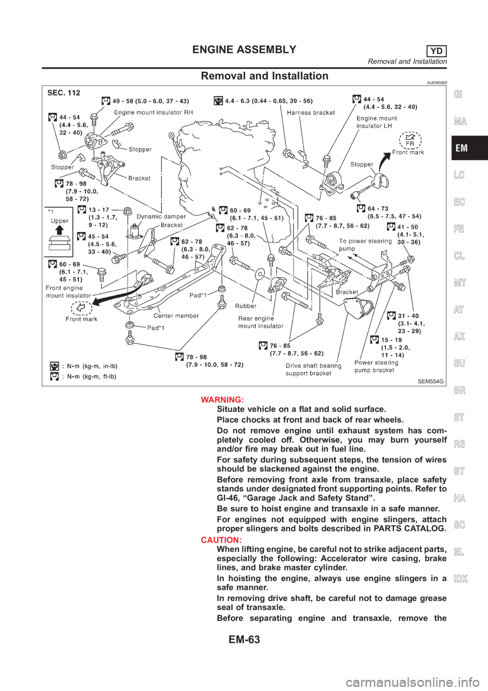
Removal and InstallationNJEM0069
SEM554G
WARNING:
Situate vehicle on a flat and solid surface.
Place chocks at front and back of rear wheels.
Do not remove engine until exhaust system has com-
pletely cooled off. Otherwise, you may burn yourself
and/or fire may break out in fuel line.
For safety during subsequent steps, the tension of wires
should be slackened against the engine.
Before removing front axle from transaxle, place safety
stands under designated front supporting points. Refer to
GI-46, “Garage Jack and Safety Stand”.
Be sure to hoist engine and transaxle in a safe manner.
For engines not equipped with engine slingers, attach
proper slingers and bolts described in PARTS CATALOG.
CAUTION:
When lifting engine, be careful not to strike adjacent parts,
especially the following: Accelerator wire casing, brake
lines, and brake master cylinder.
In hoisting the engine, always use engine slingers in a
safe manner.
In removing drive shaft, be careful not to damage grease
seal of transaxle.
Before separating engine and transaxle, remove the
GI
MA
LC
EC
FE
CL
MT
AT
AX
SU
BR
ST
RS
BT
HA
SC
EL
IDX
ENGINE ASSEMBLYYD
Removal and Installation
EM-63