NISSAN ALMERA N16 2003 Electronic Repair Manual
ALMERA N16 2003
NISSAN
NISSAN
https://www.carmanualsonline.info/img/5/57350/w960_57350-0.png
NISSAN ALMERA N16 2003 Electronic Repair Manual
Trending: wires, wiper fluid, airbag, maintenance schedule, Compression, jump start, change wheel
Page 2561 of 3189
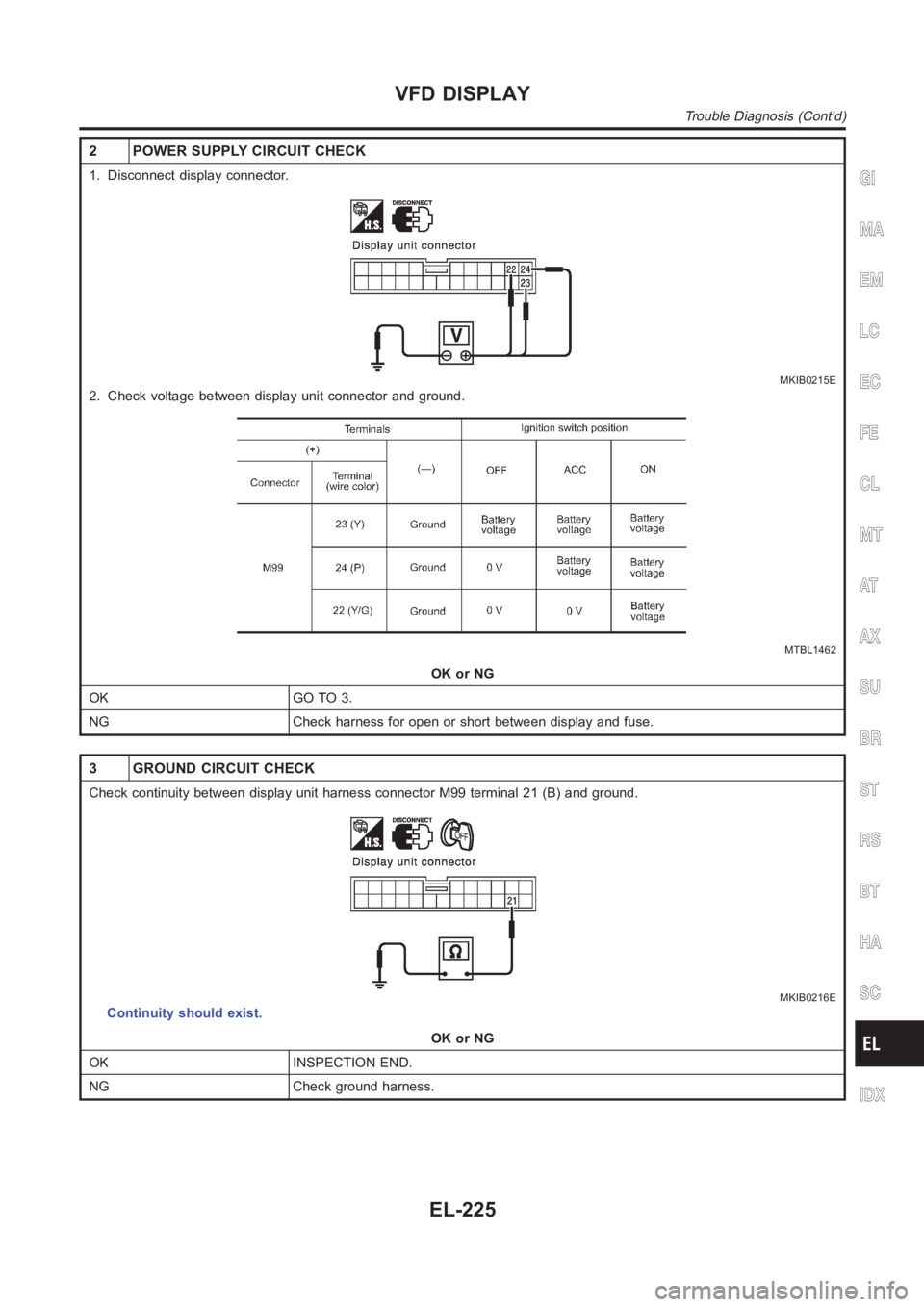
2 POWER SUPPLY CIRCUIT CHECK
1. Disconnect display connector.
MKIB0215E
2. Check voltage between display unit connector and ground.
MTBL1462
OK or NG
OK GO TO 3.
NG Check harness for open or short between display and fuse.
3 GROUND CIRCUIT CHECK
Check continuity between display unit harness connector M99 terminal 21 (B) and ground.
MKIB0216E
Continuity should exist.
OK or NG
OK INSPECTION END.
NG Check ground harness.
GI
MA
EM
LC
EC
FE
CL
MT
AT
AX
SU
BR
ST
RS
BT
HA
SC
IDX
VFD DISPLAY
Trouble Diagnosis (Cont’d)
EL-225
Page 2562 of 3189
POWER SUPPLY AND GROUND CIRCUIT CHECK FOR
MULTIFUNCTION SWITCH
NJEL0637S04
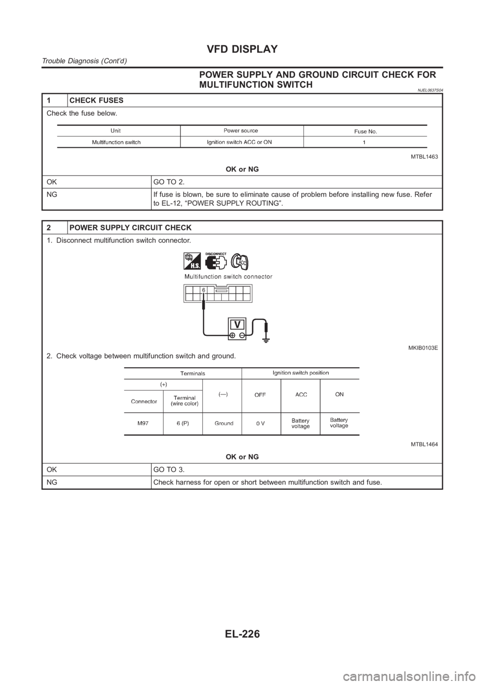
1 CHECK FUSES
Check the fuse below.
MTBL1463
OK or NG
OK GO TO 2.
NG If fuse is blown, be sure to eliminate cause of problem before installingnew fuse. Refer
to EL-12, “POWER SUPPLY ROUTING”.
2 POWER SUPPLY CIRCUIT CHECK
1. Disconnect multifunction switch connector.
MKIB0103E
2. Check voltage between multifunction switch and ground.
MTBL1464
OK or NG
OK GO TO 3.
NG Check harness for open or short between multifunction switch and fuse.
VFD DISPLAY
Trouble Diagnosis (Cont’d)
EL-226
Page 2563 of 3189
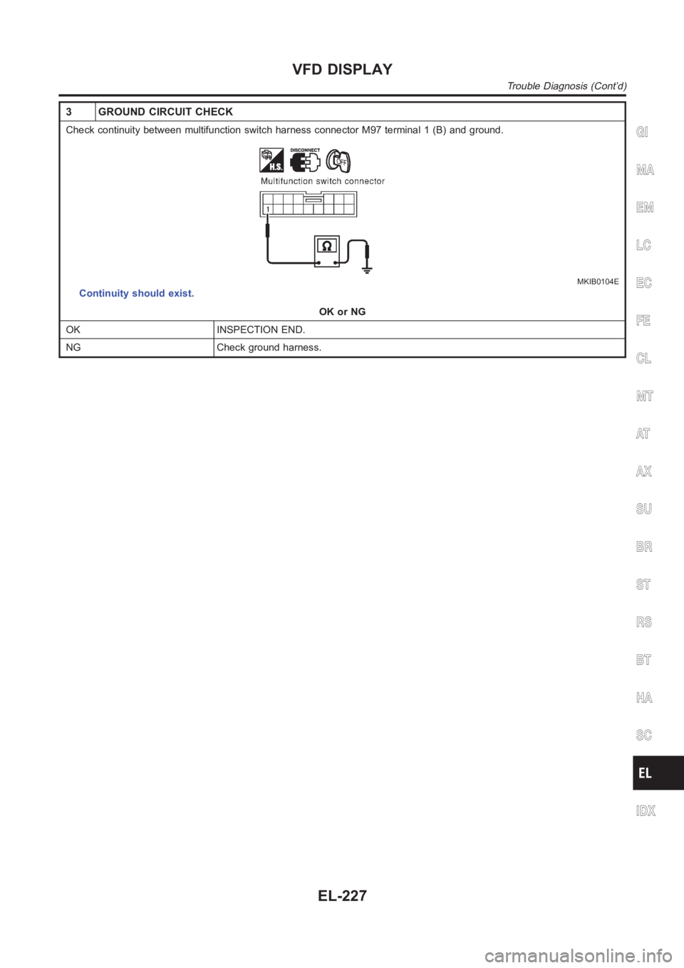
3 GROUND CIRCUIT CHECK
Check continuity between multifunction switch harness connector M97 terminal 1 (B) and ground.
MKIB0104E
Continuity should exist.
OK or NG
OK INSPECTION END.
NG Check ground harness.
GI
MA
EM
LC
EC
FE
CL
MT
AT
AX
SU
BR
ST
RS
BT
HA
SC
IDX
VFD DISPLAY
Trouble Diagnosis (Cont’d)
EL-227
Page 2564 of 3189
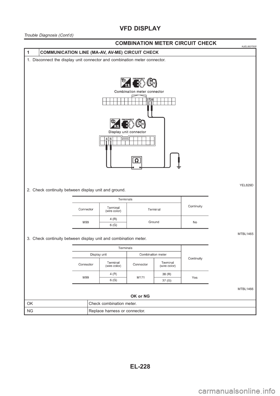
COMBINATION METER CIRCUIT CHECKNJEL0637S05
1 COMMUNICATION LINE (MA-AV, AV-ME) CIRCUIT CHECK
1. Disconnect the display unit connector and combination meter connector.
YEL829D
2. Check continuity between display unit and ground.
MTBL1465
3. Check continuity between display unit and combination meter.
MTBL1466
OK or NG
OK Check combination meter.
NG Replace harness or connector.
VFD DISPLAY
Trouble Diagnosis (Cont’d)
EL-228
Page 2565 of 3189
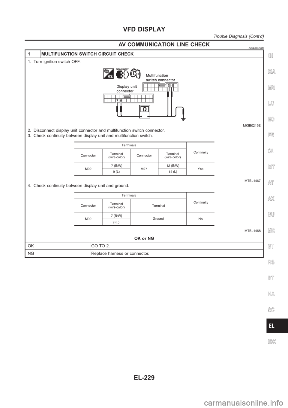
AV COMMUNICATION LINE CHECKNJEL0637S06
1 MULTIFUNCTION SWITCH CIRCUIT CHECK
1. Turn ignition switch OFF.
MKIB0219E
2. Disconnect display unit connector and multifunction switch connector.
3. Check continuity between display unit and multifunction switch.
MTBL1467
4. Check continuity between display unit and ground.
MTBL1468
OK or NG
OK GO TO 2.
NG Replace harness or connector.
GI
MA
EM
LC
EC
FE
CL
MT
AT
AX
SU
BR
ST
RS
BT
HA
SC
IDX
VFD DISPLAY
Trouble Diagnosis (Cont’d)
EL-229
Page 2566 of 3189
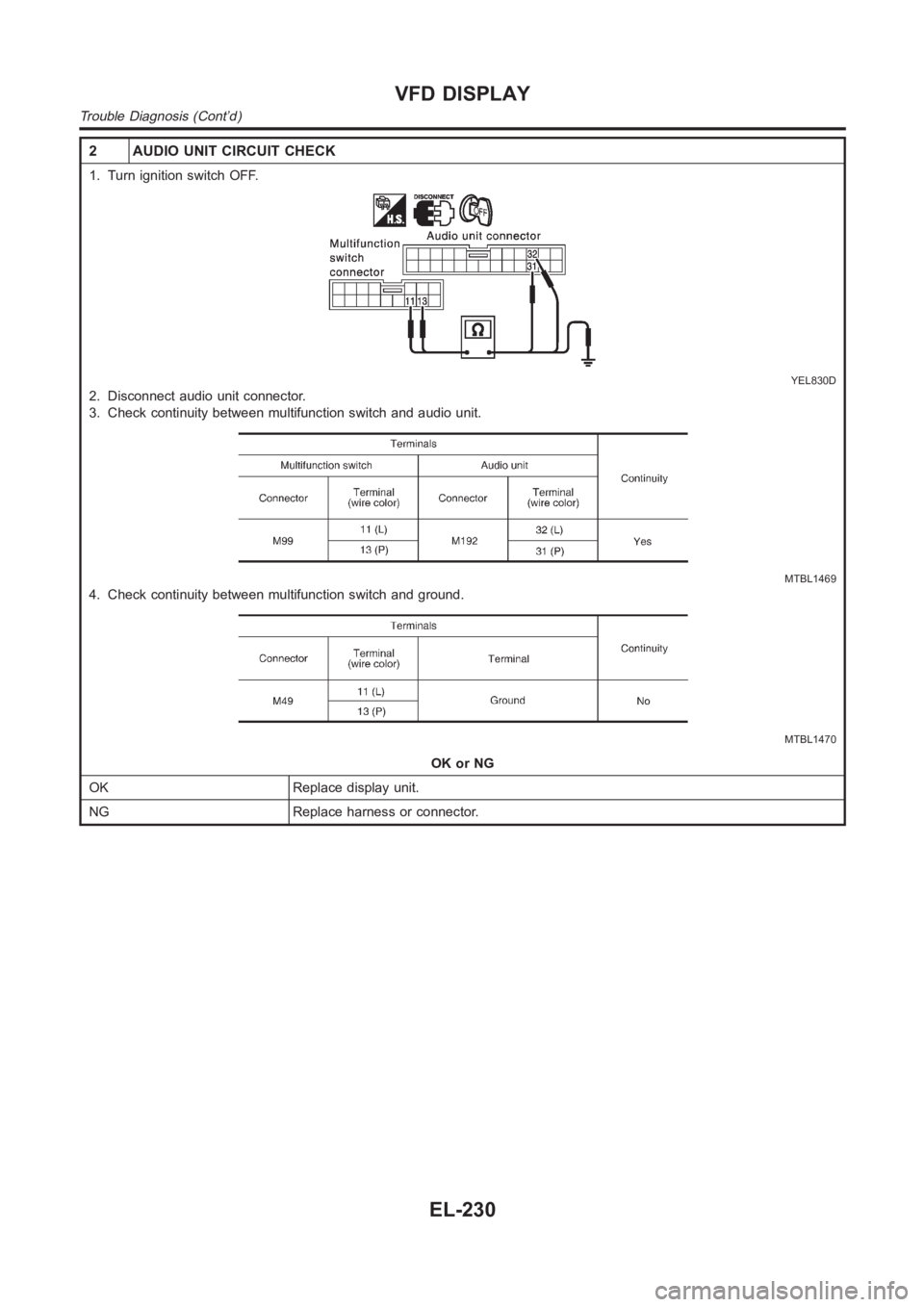
2 AUDIO UNIT CIRCUIT CHECK
1. Turn ignition switch OFF.
YEL830D
2. Disconnect audio unit connector.
3. Check continuity between multifunction switch and audio unit.
MTBL1469
4. Check continuity between multifunction switch and ground.
MTBL1470
OK or NG
OK Replace display unit.
NG Replace harness or connector.
VFD DISPLAY
Trouble Diagnosis (Cont’d)
EL-230
Page 2567 of 3189
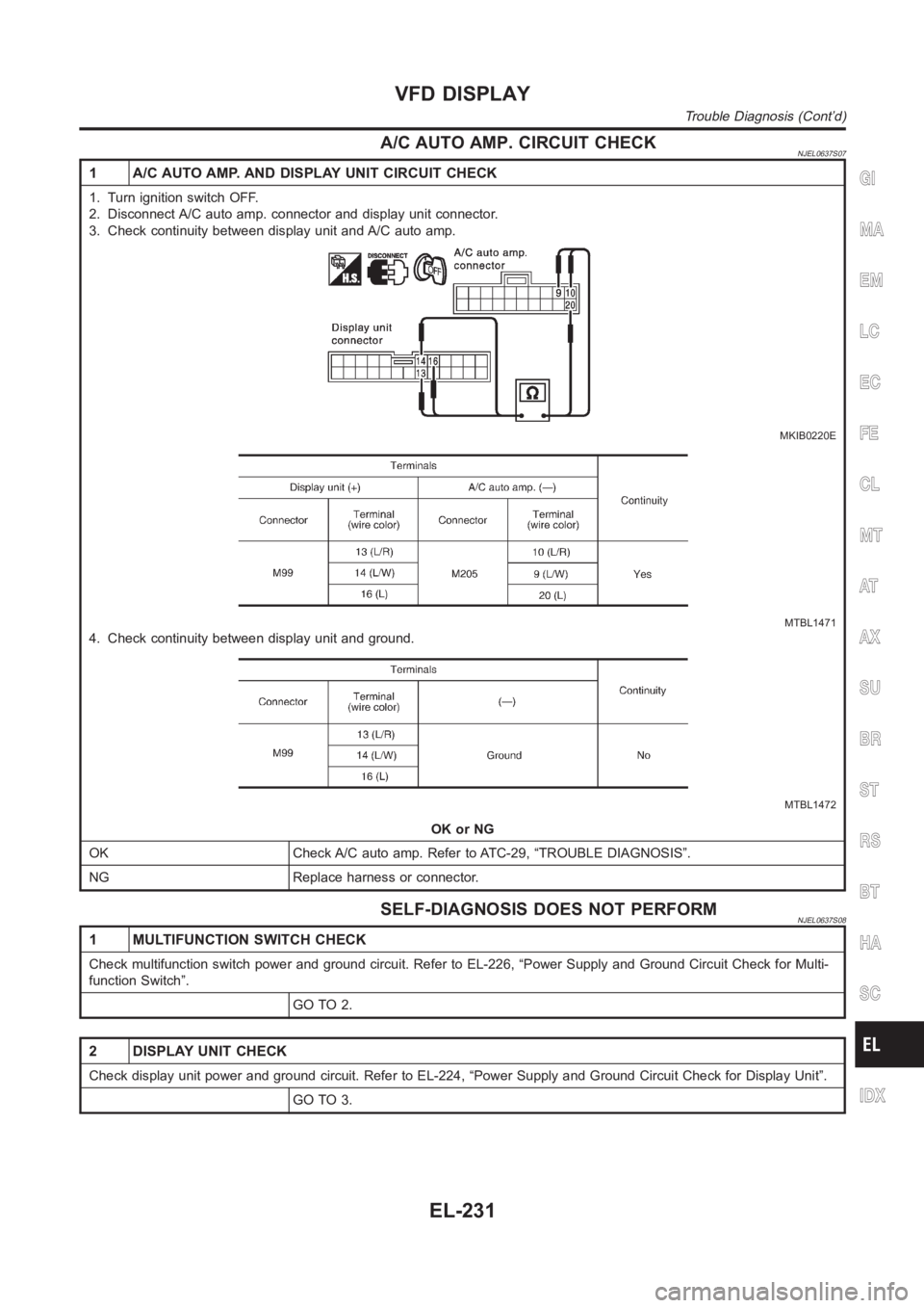
A/C AUTO AMP. CIRCUIT CHECKNJEL0637S07
1 A/C AUTO AMP. AND DISPLAY UNIT CIRCUIT CHECK
1. Turn ignition switch OFF.
2. Disconnect A/C auto amp. connector and display unit connector.
3. Check continuity between display unit and A/C auto amp.
MKIB0220E
MTBL1471
4. Check continuity between display unit and ground.
MTBL1472
OK or NG
OK Check A/C auto amp. Refer to ATC-29, “TROUBLE DIAGNOSIS”.
NG Replace harness or connector.
SELF-DIAGNOSIS DOES NOT PERFORMNJEL0637S08
1 MULTIFUNCTION SWITCH CHECK
Check multifunction switch power and ground circuit. Refer to EL-226, “Power Supply and Ground Circuit Check for Multi-
function Switch”.
GO TO 2.
2 DISPLAY UNIT CHECK
Check display unit power and ground circuit. Refer to EL-224, “Power Supply and Ground Circuit Check for Display Unit”.
GO TO 3.
GI
MA
EM
LC
EC
FE
CL
MT
AT
AX
SU
BR
ST
RS
BT
HA
SC
IDX
VFD DISPLAY
Trouble Diagnosis (Cont’d)
EL-231
Page 2568 of 3189
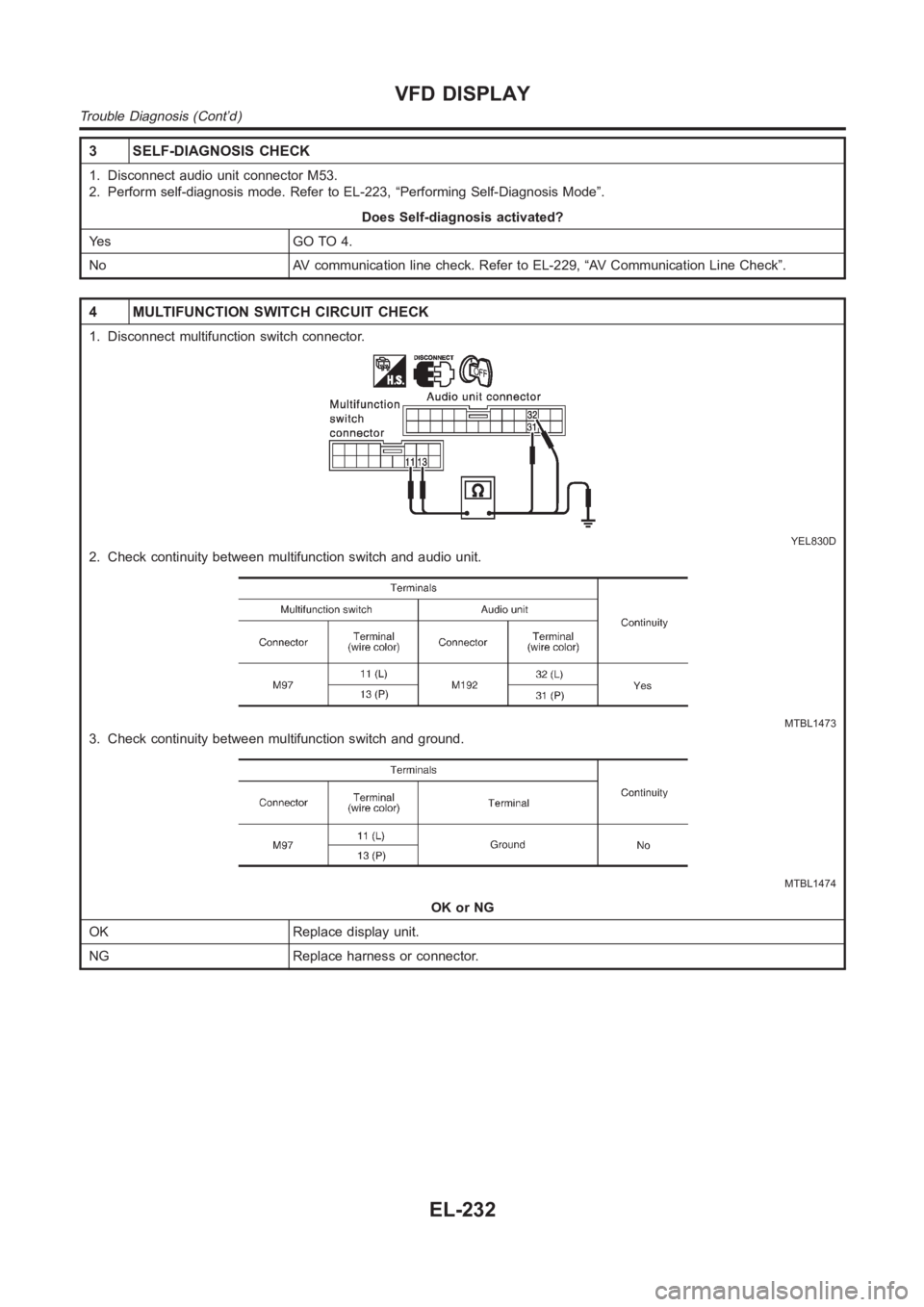
3 SELF-DIAGNOSIS CHECK
1. Disconnect audio unit connector M53.
2. Perform self-diagnosis mode. Refer to EL-223, “Performing Self-Diagnosis Mode”.
Does Self-diagnosis activated?
Ye s G O T O 4 .
No AV communication line check. Refer to EL-229, “AV Communication Line Check”.
4 MULTIFUNCTION SWITCH CIRCUIT CHECK
1. Disconnect multifunction switch connector.
YEL830D
2. Check continuity between multifunction switch and audio unit.
MTBL1473
3. Check continuity between multifunction switch and ground.
MTBL1474
OK or NG
OK Replace display unit.
NG Replace harness or connector.
VFD DISPLAY
Trouble Diagnosis (Cont’d)
EL-232
Page 2569 of 3189
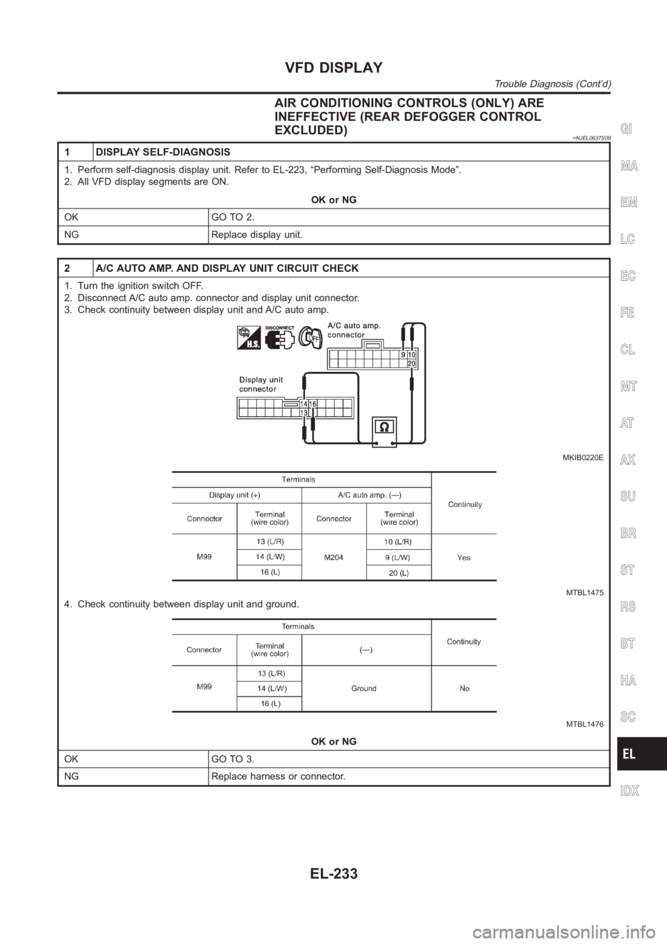
AIR CONDITIONING CONTROLS (ONLY) ARE
INEFFECTIVE (REAR DEFOGGER CONTROL
EXCLUDED)
=NJEL0637S09
1 DISPLAY SELF-DIAGNOSIS
1. Perform self-diagnosis display unit. Refer to EL-223, “Performing Self-Diagnosis Mode”.
2. All VFD display segments are ON.
OK or NG
OK GO TO 2.
NG Replace display unit.
2 A/C AUTO AMP. AND DISPLAY UNIT CIRCUIT CHECK
1. Turn the ignition switch OFF.
2. Disconnect A/C auto amp. connector and display unit connector.
3. Check continuity between display unit and A/C auto amp.
MKIB0220E
MTBL1475
4. Check continuity between display unit and ground.
MTBL1476
OK or NG
OK GO TO 3.
NG Replace harness or connector.
GI
MA
EM
LC
EC
FE
CL
MT
AT
AX
SU
BR
ST
RS
BT
HA
SC
IDX
VFD DISPLAY
Trouble Diagnosis (Cont’d)
EL-233
Page 2570 of 3189
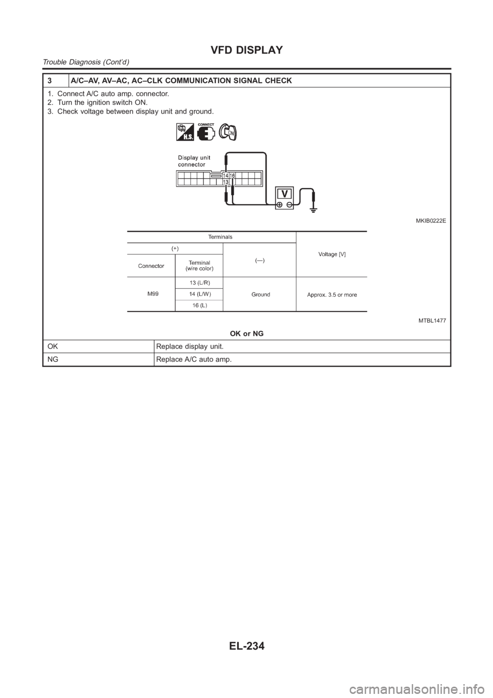
3 A/C–AV, AV–AC, AC–CLK COMMUNICATION SIGNAL CHECK
1. Connect A/C auto amp. connector.
2. Turn the ignition switch ON.
3. Check voltage between display unit and ground.
MKIB0222E
MTBL1477
OK or NG
OK Replace display unit.
NG Replace A/C auto amp.
VFD DISPLAY
Trouble Diagnosis (Cont’d)
EL-234
Trending: airbag off, turning light, Engine Control, dimensions, TEMP GAUGE, clutch, diagnostic menu
