radiator NISSAN ALMERA N16 2003 Electronic Service Manual
[x] Cancel search | Manufacturer: NISSAN, Model Year: 2003, Model line: ALMERA N16, Model: NISSAN ALMERA N16 2003Pages: 3189, PDF Size: 54.76 MB
Page 931 of 3189
![NISSAN ALMERA N16 2003 Electronic Service Manual DTC P1217 ENGINE OVER TEMPERATURE
EC-601
[QG (WITHOUT EURO-OBD)]
C
D
E
F
G
H
I
J
K
L
MA
EC
4.CHECK COOLING SYSTEM FOR LEAK
Apply pressure to the cooling system with a tester, and check if](/img/5/57350/w960_57350-930.png "NISSAN ALMERA N16 2003 Electronic Service Manual DTC P1217 ENGINE OVER TEMPERATURE
EC-601
[QG (WITHOUT EURO-OBD)]
C
D
E
F
G
H
I
J
K
L
MA
EC
4.CHECK COOLING SYSTEM FOR LEAK
Apply pressure to the cooling system with a tester, and check if")
DTC P1217 ENGINE OVER TEMPERATURE
EC-601
[QG (WITHOUT EURO-OBD)]
C
D
E
F
G
H
I
J
K
L
MA
EC
4.CHECK COOLING SYSTEM FOR LEAK
Apply pressure to the cooling system with a tester, and check if the
pressure drops.
CAUTION:
Higher than the specified pressure may cause radiator damage.
Pressure should not drop.
OK or NG
OK >> GO TO 5.
NG >> Check the following for leak
●Hose
●Radiator
●Water pump
Refer to LC-14.
5.CHECK RADIATOR CAP
Apply pressure to cap with a tester.
OK or NG
OK >> GO TO 6.
NG >> Replace radiator cap.
6.CHECK THERMOSTAT
1. Check valve seating condition at normal room temperatures.
It should seat tightly.
2. Check valve opening temperature and valve lift.
3. Check if valve is closed at 5°C (9°F) below valve opening tem-
perature.
For details, refer to LC-15.
OK or NG
OK >> GO TO 7.
NG >> Replace thermostat
7.CHECK ENGINE COOLANT TEMPERATURE SENSOR
Refer to EC-505, "
Component Inspection" .
OK or NG
OK >> GO TO 8.
NG >> Replace engine coolant temperature sensor.Testing pressure: 157 kPa (1.57 bar 1.6 kg/cm
2 , 23
psi)
SLC754A
Radiator cap relief pressure: 59 - 98 kPa
(0.59 - 0.98 bar 0.6 - 1.0 kg/
cm
2 , 9 - 14 psi)
SLC755A
Valve opening temperature: 82°C (180°F) [standard]
Valve lift: More than 8 mm/95°C
(0.31 in/203°F)
SLC343
Page 935 of 3189
![NISSAN ALMERA N16 2003 Electronic Service Manual DTC P1217 ENGINE OVER TEMPERATURE
EC-605
[QG (WITHOUT EURO-OBD)]
C
D
E
F
G
H
I
J
K
L
MA
EC
7.CHECK COOLING FAN MOTORS
Refer to EC-606, "
Component Inspection" .
OK or NG
OK >> GO TO 8.
NG >> R](/img/5/57350/w960_57350-934.png "NISSAN ALMERA N16 2003 Electronic Service Manual DTC P1217 ENGINE OVER TEMPERATURE
EC-605
[QG (WITHOUT EURO-OBD)]
C
D
E
F
G
H
I
J
K
L
MA
EC
7.CHECK COOLING FAN MOTORS
Refer to EC-606, \"
Component Inspection\" .
OK or NG
OK >> GO TO 8.
NG >> R")
DTC P1217 ENGINE OVER TEMPERATURE
EC-605
[QG (WITHOUT EURO-OBD)]
C
D
E
F
G
H
I
J
K
L
MA
EC
7.CHECK COOLING FAN MOTORS
Refer to EC-606, "
Component Inspection" .
OK or NG
OK >> GO TO 8.
NG >> Replace cooling fan motors.
8.CHECK SMART ENTRANCE CONTROL UNIT
Refer to EL-368.
OK or NG
OK >> GO TO 9.
NG >> Replace cooling fan motors.
9.CHECK INTERMITTENT INCIDENT
Perform EC-485, "
TROUBLE DIAGNOSIS FOR INTERMITTENT INCIDENT" .
>>INSPECTION END
Main 12 Causes of OverheatingEBS00KJ7
*1: Turn the ignition switch ON.
*2: Engine running at 3,000 rpm for 10 minutes.
*3: Drive at 90 km/h (55 MPH) for 30 minutes and then let idle for 10 minutes. Engine Step Inspection item Equipment Standard Reference page
OFF 1
●Blocked radiator
●Blocked condenser
●Blocked radiator grille
●Blocked bumper
●Visual No blocking —
2
●Coolant mixture●Coolant tester 50 - 50% coolant mixture See MA-19.
3
●Coolant level●Visual Coolant up to MAX level
in reservoir tank and radi-
ator filler neckSee MA-7.
4
●Radiator cap●Pressure tester 59 - 98 kPa
(0.59 - 0.98 bar, 0.6 - 1.0
kg/cm
2 , 9 - 14 psi) (Limit)See LC-12.
ON*
25●Coolant leaks●Visual No leaks See LC-11.
ON*
26●Thermostat●Touch the upper and
lower radiator hosesBoth hoses should be hot See LC-15, and LC-16.
ON*
17●Cooling fan●CONSULT-II Operating See trouble diagnosis for
DTC P1217 (EC-596
).
OFF 8
●Combustion gas leak●Color checker chemical
tester 4 Gas analyzerNegative —
ON*
39●Coolant temperature
gauge●Visual Gauge less than 3/4
when driving—
●Coolant overflow to
reservoir tank●Visual No overflow during driving
and idlingSee MA-7.
OFF*
410●Coolant return from
reservoir tank to radia-
tor●Visual Should be initial level in
reservoir tankSee MA-7.
OFF 11
●Cylinder head●Straight gauge feeler
gauge0.1 mm (0.004 in) Maxi-
mum distortion (warping)SeeEM-57, "CYLINDER
HEAD" .
12
●Cylinder block and pis-
tons●Visual No scuffing on cylinder
walls or pistonSeeEM-70, "CYLINDER
BLOCK" .
Page 1185 of 3189
![NISSAN ALMERA N16 2003 Electronic Service Manual TERMI-
NAL
NO.WIRE
COLORITEM CONDITION DATA(DC Voltage)
221 LG/B Cooling fan relay (High)[Engine is running]
Cooling fans are not operating
Cooling fans are operating at low speedBATTERY VOLTAGE
(11 -](/img/5/57350/w960_57350-1184.png "NISSAN ALMERA N16 2003 Electronic Service Manual TERMI-
NAL
NO.WIRE
COLORITEM CONDITION DATA(DC Voltage)
221 LG/B Cooling fan relay (High)[Engine is running]
Cooling fans are not operating
Cooling fans are operating at low speedBATTERY VOLTAGE
(11 -")
TERMI-
NAL
NO.WIRE
COLORITEM CONDITION DATA(DC Voltage)
221 LG/B Cooling fan relay (High)[Engine is running]
Cooling fans are not operating
Cooling fans are operating at low speedBATTERY VOLTAGE
(11 - 14V)
[Engine is running]
Cooling fans are operating at high speedApproximately 0.1V
On Board Diagnosis LogicNJEC0663This diagnosis continuously monitors the engine coolant temperature.
If the cooling fan or another component in the cooling system malfunctions, engine coolant temperature will
rise.
When the engine coolant temperature reaches an abnormally high temperature condition, a malfunction is
indicated.
This self-diagnosis has the one trip detection logic.
DTC Malfunction is detected when ... Check Items (Possible Cause)
P1217
0208Cooling fan does not operate properly (Overheat).
Cooling fan system does not operate properly
(Overheat).
Engine coolant was not added to the system using
the proper filling method.Harness or connectors
(The cooling fan circuit is open or shorted.)
Cooling fan
Radiator hose
Radiator
Radiator cap
Water pump
Thermostat
Engine coolant temperature sensor
For more information, refer to “MAIN 12 CAUSES OF
OVERHEATING”, EC-144.
CAUTION:
When a malfunction is indicated, be sure to replace the coolant following the procedure in the LC-43,
“Changing Engine Coolant”. Also, replace the engine oil.
1) Fill radiator with coolant up to specified level with a filling speed of 2liters per minute. Be sure
to use coolant with the proper mixture ratio. Refer to MA-21, “Engine Coolant Mixture Ratio”.
2) After refilling coolant, run engine to ensure that no water-flow noise is emitted.
GI
MA
EM
LC
FE
CL
MT
AT
AX
SU
BR
ST
RS
BT
HA
SC
EL
IDX
DTC P1217 OVER HEATYD
ECM Terminals and Reference Value (Cont’d)
EC-131
Page 1186 of 3189
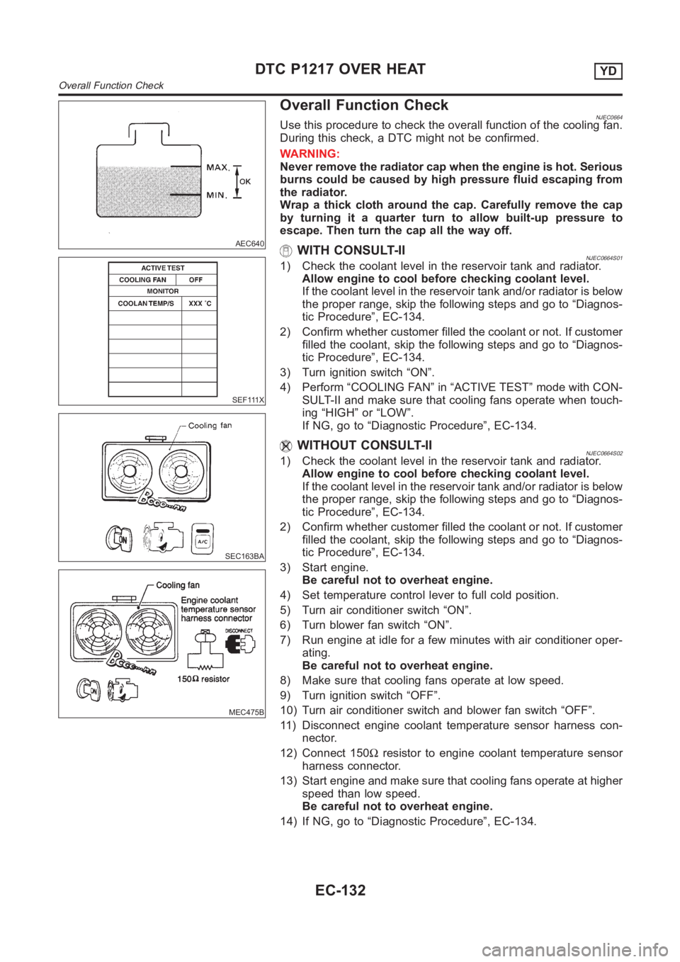
AEC640
Overall Function Check
SEF111X
SEC163BA
MEC475B
NJEC0664Use this procedure to check the overall function of the cooling fan.
During this check, a DTC might not be confirmed.
WARNING:
Never remove the radiator cap when the engine is hot. Serious
burns could be caused by high pressure fluid escaping from
the radiator.
Wrap a thick cloth around the cap. Carefully remove the cap
by turning it a quarter turn to allow built-up pressure to
escape. Then turn the cap all the way off.
WITH CONSULT-IINJEC0664S011) Check the coolant level in the reservoir tank and radiator.
Allow engine to cool before checking coolant level.
If the coolant level in the reservoir tank and/or radiator is below
the proper range, skip the following steps and go to “Diagnos-
tic Procedure”, EC-134.
2) Confirm whether customer filled the coolant or not. If customer
filled the coolant, skip the following steps and go to “Diagnos-
tic Procedure”, EC-134.
3) Turn ignition switch “ON”.
4) Perform “COOLING FAN” in “ACTIVE TEST” mode with CON-
SULT-II and make sure that cooling fans operate when touch-
ing “HIGH” or “LOW”.
If NG, go to “Diagnostic Procedure”, EC-134.
WITHOUT CONSULT-IINJEC0664S021) Check the coolant level in the reservoir tank and radiator.
Allow engine to cool before checking coolant level.
If the coolant level in the reservoir tank and/or radiator is below
the proper range, skip the following steps and go to “Diagnos-
tic Procedure”, EC-134.
2) Confirm whether customer filled the coolant or not. If customer
filled the coolant, skip the following steps and go to “Diagnos-
tic Procedure”, EC-134.
3) Start engine.
Be careful not to overheat engine.
4) Set temperature control lever to full cold position.
5) Turn air conditioner switch “ON”.
6) Turn blower fan switch “ON”.
7) Run engine at idle for a few minutes with air conditioner oper-
ating.
Be careful not to overheat engine.
8) Make sure that cooling fans operate at low speed.
9) Turn ignition switch “OFF”.
10) Turn air conditioner switch and blower fan switch “OFF”.
11) Disconnect engine coolant temperature sensor harness con-
nector.
12) Connect 150Ωresistor to engine coolant temperature sensor
harness connector.
13) Start engine and make sure that cooling fans operate at higher
speed than low speed.
Be careful not to overheat engine.
14) If NG, go to “Diagnostic Procedure”, EC-134.
DTC P1217 OVER HEATYD
Overall Function Check
EC-132
Page 1190 of 3189
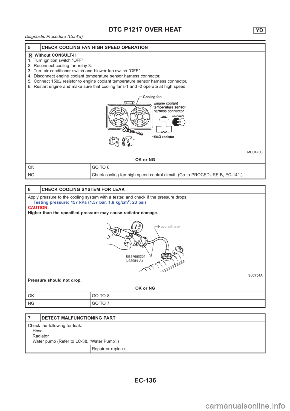
5 CHECK COOLING FAN HIGH SPEED OPERATION
Without CONSULT-II
1. Turn ignition switch “OFF”.
2. Reconnect cooling fan relay-3.
3. Turn air conditioner switch and blower fan switch “OFF”.
4. Disconnect engine coolant temperature sensor harness connector.
5. Connect 150Ωresistor to engine coolant temperature sensor harness connector.
6. Restart engine and make sure that cooling fans-1 and -2 operate at high speed.
MEC475B
OK or NG
OK GO TO 6.
NG Check cooling fan high speed control circuit. (Go to PROCEDURE B, EC-141.)
6 CHECK COOLING SYSTEM FOR LEAK
Apply pressure to the cooling system with a tester, and check if the pressure drops.
Testing pressure: 157 kPa (1.57 bar, 1.6 kg/cm2,23psi)
CAUTION:
Higher than the specified pressure may cause radiator damage.
SLC754A
Pressure should not drop.
OK or NG
OK GO TO 8.
NG GO TO 7.
7 DETECT MALFUNCTIONING PART
Check the following for leak.
Hose
Radiator
Water pump (Refer to LC-38, “Water Pump”.)
Repair or replace.
DTC P1217 OVER HEATYD
Diagnostic Procedure (Cont’d)
EC-136
Page 1191 of 3189
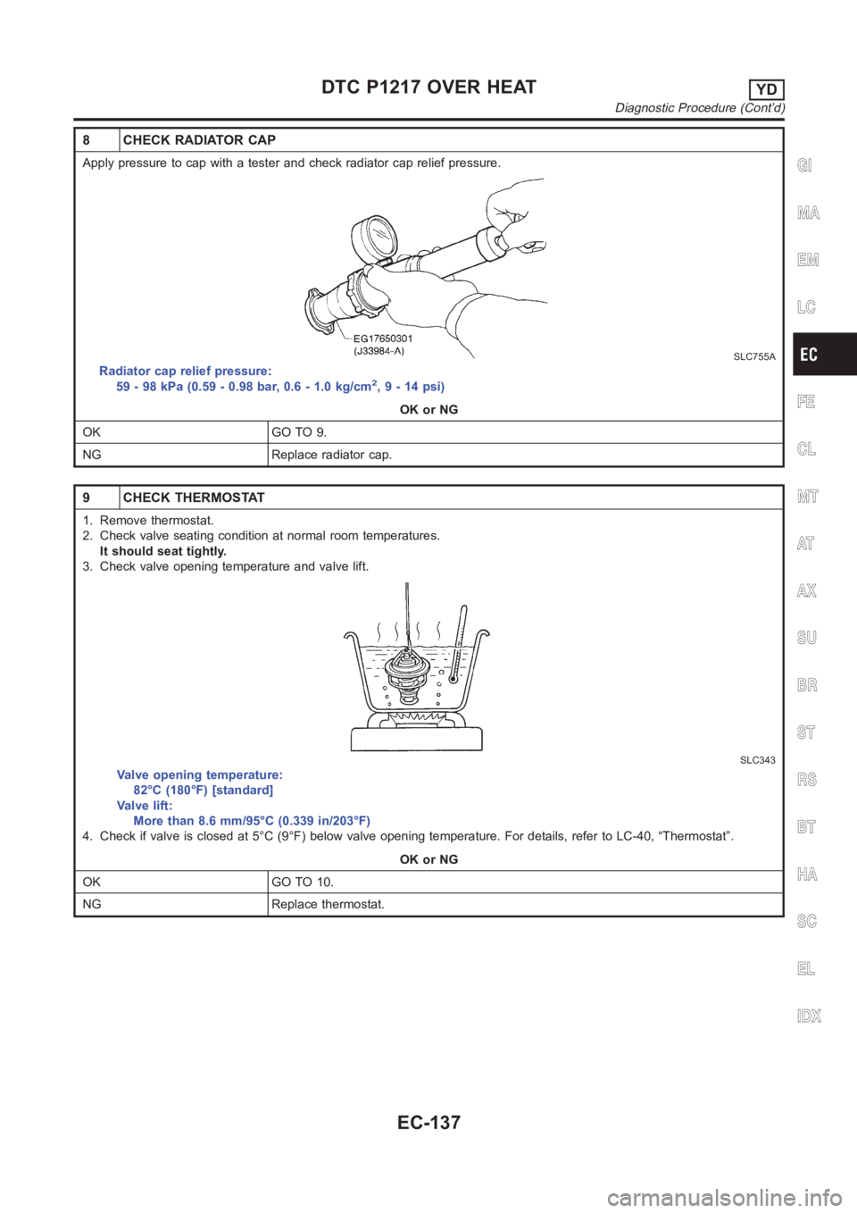
8 CHECK RADIATOR CAP
Apply pressure to cap with a tester and check radiator cap relief pressure.
SLC755A
Radiator cap relief pressure:
59 - 98 kPa (0.59 - 0.98 bar, 0.6 - 1.0 kg/cm2,9-14psi)
OK or NG
OK GO TO 9.
NG Replace radiator cap.
9 CHECK THERMOSTAT
1. Remove thermostat.
2. Check valve seating condition at normal room temperatures.
It should seat tightly.
3. Check valve opening temperature and valve lift.
SLC343
Valve opening temperature:
82°C (180°F) [standard]
Valve lift:
More than 8.6 mm/95°C (0.339 in/203°F)
4. Check if valve is closed at 5°C (9°F) below valve opening temperature. For details, refer to LC-40, “Thermostat”.
OK or NG
OK GO TO 10.
NG Replace thermostat.
GI
MA
EM
LC
FE
CL
MT
AT
AX
SU
BR
ST
RS
BT
HA
SC
EL
IDX
DTC P1217 OVER HEATYD
Diagnostic Procedure (Cont’d)
EC-137
Page 1198 of 3189
9 CHECK INTERMITTENT INCIDENT
1. Perform “TROUBLE DIAGNOSIS FOR INTERMITTENT INCIDENT”, EC-71.
INSPECTION END
Main 12 Causes of OverheatingNJEC0667
Engine Step Inspection item Equipment Condition Reference page
OFF 1 Blocked radiator
Blocked radiator grille
Blocked bumperVisual No blocking —
2 Coolant mixture Coolant tester 50 - 50% coolant mixture See MA-19, “RECOM-
MENDED FLUIDS AND
LUBRICANTS”.
3 Coolant level Visual Coolant up to MAX level
in reservoir tank and
radiator filler neckSee LC-17, “Changing
Engine Coolant”.
4 Radiator cap Pressure tester 78 - 98 kPa
(0.78 - 0.98 bar, 0.8 - 1.0
kg/cm
2, 11 - 14 psi)See LC-37, “System
Check”.
ON*
25 Coolant leaks Visual No leaks See LC-37, “System
Check”.
ON*
26 Thermostat Touch the upper and
lower radiator hosesBoth hoses should be
hotSee LC-40, “Thermostat”
and “Radiator”.
ON*
17 Cooling fan CONSULT-II Operating See Trouble Diagnosis
for DTC P1217, EC-130.
OFF 8 Combustion gas leak Color checker chemi-
cal tester 4 Gas ana-
lyzerNegative —
ON*
39 Coolant temperature
gaugeVisual Gauge less than 3/4
when driving—
Coolant overflow to
reservoir tankVisual No overflow during driv-
ing and idlingSee LC-43, “Changing
Engine Coolant”.
OFF*
410 Coolant return from
reservoir tank to radia-
torVisual Should be initial level in
reservoir tankSee LC-43, “REFILLING
ENGINE COOLANT”.
OFF 11 Cylinder head Straight gauge feeler
gauge0.1mm (0.004 in) Maxi-
mum distortion (warping)See EM-48, “Inspection”.
12 Cylinder block and pis-
tonsVisual No scuffing on cylinder
walls or pistonSee EM-70, “Inspection”.
*1: Turn the ignition switch ON.
*2: Engine running at 3,000 rpm for 10 minutes.
*3: Drive at 90 km/h (55 MPH) for 30 minutes and then let idle for 10 minutes.
*4: After 60 minutes of cool down time.
For more information, refer to LC-46, “OVERHEATING CAUSE ANALYSIS”.
DTC P1217 OVER HEATYD
Diagnostic Procedure (Cont’d)
EC-144
Page 1469 of 3189
A/T FLUID
AT-13
D
E
F
G
H
I
J
K
L
MA
B
AT
A/T FLUIDPFP:KLE40
Checking A/T FluidECS007NC
1. Warm up engine.
2. Check for fluid leakage.
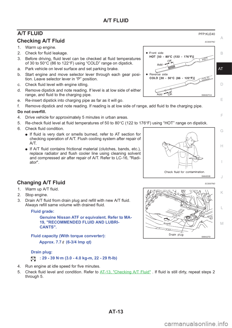
3. Before driving, fluid level can be checked at fluid temperatures
of 30 to 50°C (86 to 122°F) using “COLD” range on dipstick.
a. Park vehicle on level surface and set parking brake.
b. Start engine and move selector lever through each gear posi-
tion. Leave selector lever in “P” position.
c. Check fluid level with engine idling.
d. Remove dipstick and note reading. If level is at low side of either
range, and fluid to the charging pipe.
e. Re-insert dipstick into charging pipe as far as it will go.
f. Remove dipstick and note reading. If reading is at low side of range, add fluid to the charging pipe.
Do not overfill.
4. Drive vehicle for approximately 5 minutes in urban areas.
5. Re-check fluid level at fluid temperatures of 50 to 80°C (122 to 176°F) using “HOT” range on dipstick.
6. Check fluid condition.
●If fluid is very dark or smells burned, refer to AT section for
checking operation of A/T. Flush cooling system after repair of
A/T.
●If A/T fluid contains frictional material (clutches, bands, etc.),
replace radiator and flush cooler line using cleaning solvent
and compressed air after repair of A/T. Refer to LC-16, "Radi-
ator".
Changing A/T FluidECS007ND
1. Warm up A/T fluid.
2. Stop engine.
3. Drain A/T fluid from drain plug and refill with new A/T fluid.
Always refill same volume with drained fluid.
4. Run engine at idle speed for five minutes.
5. Check fluid level and condition. Refer to AT- 1 3 , "
Checking A/T Fluid" . If fluid is still dirty, repeat steps 2
through 5.
SMA827CA
SMA853B
Fluid grade:
Genuine Nissan ATF or equivalent. Refer to MA-
19, "RECOMMENDED FLUID AND LUBRI-
CANTS".
Fluid capacity (With torque converter):
Approx. 7.7 (6-3/4 lmp qt)
Drain plug:
: 29 - 39 N·m (3.0 - 4.0 kg-m, 22 - 29 ft-lb)
SMA027D
Page 1875 of 3189
![NISSAN ALMERA N16 2003 Electronic Service Manual DISASSEMBLY
AT-419
[ALL]
D
E
F
G
H
I
J
K
L
MA
B
AT
4. Remove A/T fluid charging pipe and fluid cooler tube.
5. Set manual shaft to position P.
6. Remove park/neutral position (PNP) switch.
7. Remove o](/img/5/57350/w960_57350-1874.png "NISSAN ALMERA N16 2003 Electronic Service Manual DISASSEMBLY
AT-419
[ALL]
D
E
F
G
H
I
J
K
L
MA
B
AT
4. Remove A/T fluid charging pipe and fluid cooler tube.
5. Set manual shaft to position P.
6. Remove park/neutral position (PNP) switch.
7. Remove o")
DISASSEMBLY
AT-419
[ALL]
D
E
F
G
H
I
J
K
L
MA
B
AT
4. Remove A/T fluid charging pipe and fluid cooler tube.
5. Set manual shaft to position P.
6. Remove park/neutral position (PNP) switch.
7. Remove oil pan and oil pan gasket.
●Do not reuse oil pan bolts.
8. Check foreign materials in oil pan to help determine causes of
malfunction. If the fluid is very dark, smells burned, or contains
foreign particles, the frictional material (clutches, band) may
need replacement. A tacky film that will not wipe clean indicates
varnish build up. Varnish can cause valves, servo, and clutches
to stick and can inhibit pump pressure.
●If frictional material is detected, replace radiator after
repair of A/T. Refer to LC-16, "RADIATOR".
9. Remove control valve assembly according to the following pro-
cedures.
a. Remove control valve assembly mounting bolts A, B and C.
MCIB9012E
SAT023JA
SAT128E
AAT260A
Page 2080 of 3189
ATC-100
TROUBLE DIAGNOSIS
Ambient Sensor Circuit
EJS001ZV
COMPONENT DESCRIPTION
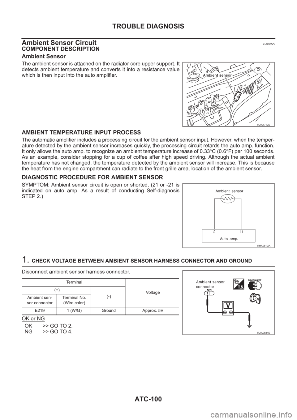
Ambient Sensor
The ambient sensor is attached on the radiator core upper support. It
detects ambient temperature and converts it into a resistance value
which is then input into the auto amplifier.
AMBIENT TEMPERATURE INPUT PROCESS
The automatic amplifier includes a processing circuit for the ambient sensor input. However, when the temper-
ature detected by the ambient sensor increases quickly, the processing circuit retards the auto amp. function.
It only allows the auto amp. to recognize an ambient temperature increase of 0.33°C (0.6°F) per 100 seconds.
As an example, consider stopping for a cup of coffee after high speed driving. Although the actual ambient
temperature has not changed, the temperature detected by the ambient sensor will increase. This is because
the heat from the engine compartment can radiate to the front grille area, location of the ambient sensor.
DIAGNOSTIC PROCEDURE FOR AMBIENT SENSOR
SYMPTOM: Ambient sensor circuit is open or shorted. (21 or -21 is
indicated on auto amp. As a result of conducting Self-diagnosis
STEP 2.)
1. CHECK VOLTAGE BETWEEN AMBIENT SENSOR HARNESS CONNECTOR AND GROUND
Disconnect ambient sensor harness connector.
OK or NG
OK >> GO TO 2.
NG >> GO TO 4.
RJIA1712E
RHA051GA
Terminal
Voltage (+)
(-)
Ambient sen-
sor connectorTerminal No.
(Wire color)
E219 1 (W/G) Ground Approx. 5V
RJIA0681E