jump cable NISSAN ALMERA N16 2003 Electronic Repair Manual
[x] Cancel search | Manufacturer: NISSAN, Model Year: 2003, Model line: ALMERA N16, Model: NISSAN ALMERA N16 2003Pages: 3189, PDF Size: 54.76 MB
Page 29 of 3189
voltage; open is further down the circuit than the relay.
no voltage; open is between SW1 and relay (point B).
5) Close the relay and probe at the solenoid.
voltage; open is further down the circuit than the solenoid.
no voltage; open is between relay and solenoid (point C).
Any powered circuit can be diagnosed using the approach in the
above example.
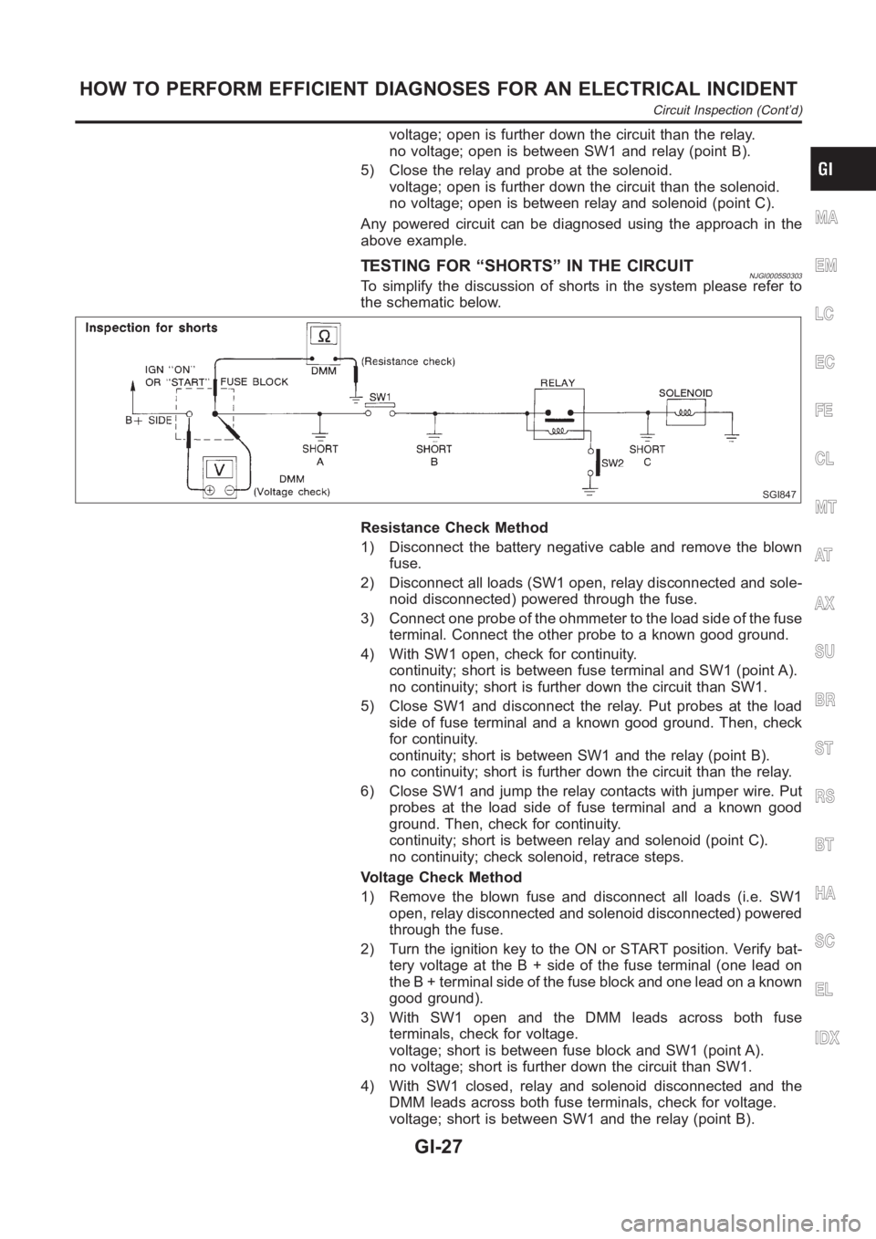
TESTING FOR “SHORTS” IN THE CIRCUITNJGI0005S0303To simplify the discussion of shorts in the system please refer to
the schematic below.
SGI847
Resistance Check Method
1) Disconnect the battery negative cable and remove the blown
fuse.
2) Disconnect all loads (SW1 open, relay disconnected and sole-
noid disconnected) powered through the fuse.
3) Connect one probe of the ohmmeter to the load side of the fuse
terminal. Connect the other probe to a known good ground.
4) With SW1 open, check for continuity.
continuity; short is between fuse terminal and SW1 (point A).
no continuity; short is further down the circuit than SW1.
5) Close SW1 and disconnect the relay. Put probes at the load
side of fuse terminal and a known good ground. Then, check
for continuity.
continuity; short is between SW1 and the relay (point B).
no continuity; short is further down the circuit than the relay.
6) Close SW1 and jump the relay contacts with jumper wire. Put
probes at the load side of fuse terminal and a known good
ground. Then, check for continuity.
continuity; short is between relay and solenoid (point C).
no continuity; check solenoid, retrace steps.
Voltage Check Method
1) Remove the blown fuse and disconnect all loads (i.e. SW1
open, relay disconnected and solenoid disconnected) powered
through the fuse.
2) Turn the ignition key to the ON or START position. Verify bat-
tery voltage at the B + side of the fuse terminal (one lead on
the B + terminal side of the fuse block and one lead on a known
good ground).
3) With SW1 open and the DMM leads across both fuse
terminals, check for voltage.
voltage; short is between fuse block and SW1 (point A).
no voltage; short is further down the circuit than SW1.
4) With SW1 closed, relay and solenoid disconnected and the
DMM leads across both fuse terminals, check for voltage.
voltage; short is between SW1 and the relay (point B).
MA
EM
LC
EC
FE
CL
MT
AT
AX
SU
BR
ST
RS
BT
HA
SC
EL
IDX
HOW TO PERFORM EFFICIENT DIAGNOSES FOR AN ELECTRICAL INCIDENT
Circuit Inspection (Cont’d)
GI-27
Page 1237 of 3189
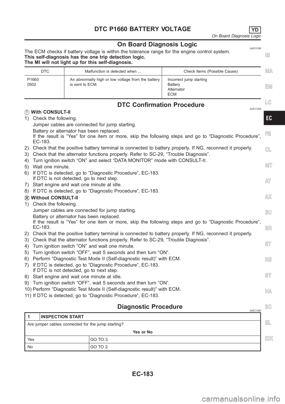
On Board Diagnosis LogicNJEC1258The ECM checks if battery voltage is within the tolerance range for the engine control system.
This self-diagnosis has the one trip detection logic.
The MI will not light up for this self-diagnosis.
DTC Malfunction is detected when ... Check Items (Possible Cause)
P1660
0502An abnormally high or low voltage from the battery
is sent to ECM.Incorrect jump starting
Battery
Alternator
ECM
DTC Confirmation ProcedureNJEC1259With CONSULT-II
1) Check the following.
Jumper cables are connected for jump starting.
Battery or alternator has been replaced.
If the result is “Yes” for one item or more, skip the following steps and go to“Diagnostic Procedure”,
EC-183.
2) Check that the positive battery terminal is connected to battery properly. If NG, reconnect it properly.
3) Check that the alternator functions properly. Refer to SC-29, “TroubleDiagnosis”.
4) Turn ignition switch “ON” and select “DATA MONITOR” mode with CONSULT-II.
5) Wait one minute.
6) If DTC is detected, go to “Diagnostic Procedure”, EC-183.
If DTC is not detected, go to next step.
7) Start engine and wait one minute at idle.
8) If DTC is detected, go to “Diagnostic Procedure”, EC-183.
Without CONSULT-II
1) Check the following.
Jumper cables are connected for jump starting.
Battery or alternator has been replaced.
If the result is “Yes” for one item or more, skip the following steps and go to“Diagnostic Procedure”,
EC-183.
2) Check that the positive battery terminal is connected to battery properly. If NG, reconnect it properly.
3) Check that the alternator functions properly. Refer to SC-29, “TroubleDiagnosis”.
4) Turn ignition switch “ON” and wait one minute.
5) Turn ignition switch “OFF”, wait 5 seconds and then turn “ON”.
6) Perform “Diagnostic Test Mode II (Self-diagnostic result)” with ECM.
7) If DTC is detected, go to “Diagnostic Procedure”, EC-183.
If DTC is not detected, go to next step.
8) Start engine and wait one minute at idle.
9) Turn ignition switch “OFF”, wait 5 seconds and then turn “ON”.
10) Perform “Diagnostic Test Mode II (Self-diagnostic result)” with ECM.
11) If DTC is detected, go to “Diagnostic Procedure”, EC-183.
Diagnostic ProcedureNJEC1260
1 INSPECTION START
Are jumper cables connected for the jump starting?
YesorNo
Ye s G O T O 3 .
No GO TO 2.
GI
MA
EM
LC
FE
CL
MT
AT
AX
SU
BR
ST
RS
BT
HA
SC
EL
IDX
DTC P1660 BATTERY VOLTAGEYD
On Board Diagnosis Logic
EC-183
Page 1238 of 3189
2 CHECK BATTERY AND ALTERNATOR
Check that the proper type of battery and alternator is installed.
Refer to SC-37, “Battery” and SC-38, “Alternator”.
OK or NG
OK GO TO 5.
NG Replace with a proper one.
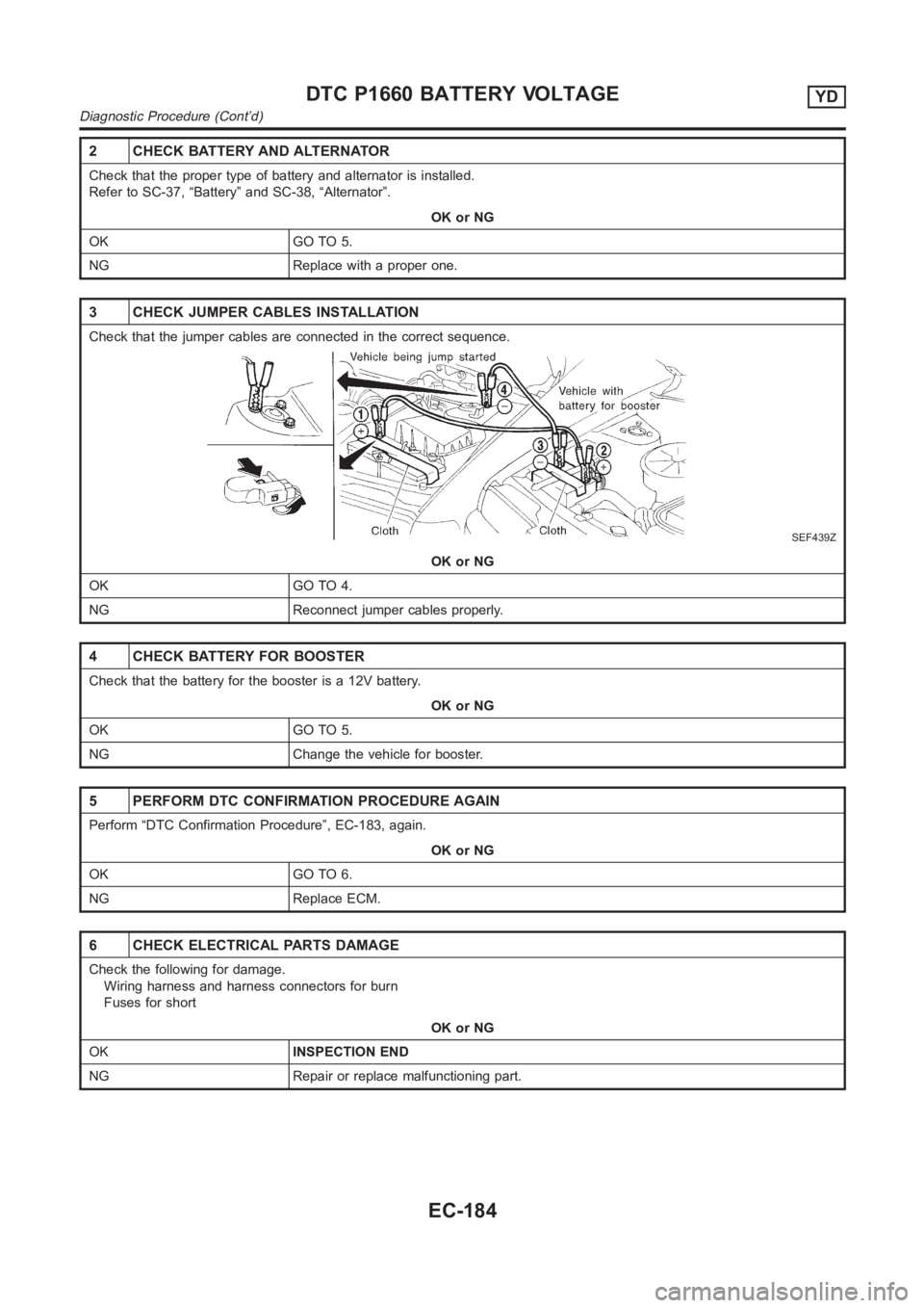
3 CHECK JUMPER CABLES INSTALLATION
Check that the jumper cables are connected in the correct sequence.
SEF439Z
OK or NG
OK GO TO 4.
NG Reconnect jumper cables properly.
4 CHECK BATTERY FOR BOOSTER
Check that the battery for the booster is a 12V battery.
OK or NG
OK GO TO 5.
NG Change the vehicle for booster.
5 PERFORM DTC CONFIRMATION PROCEDURE AGAIN
Perform “DTC Confirmation Procedure”, EC-183, again.
OK or NG
OK GO TO 6.
NG Replace ECM.
6 CHECK ELECTRICAL PARTS DAMAGE
Check the following for damage.
Wiring harness and harness connectors for burn
Fuses for short
OK or NG
OKINSPECTION END
NG Repair or replace malfunctioning part.
DTC P1660 BATTERY VOLTAGEYD
Diagnostic Procedure (Cont’d)
EC-184
Page 2549 of 3189
Trouble DiagnosesNJEL0385AUDIO UNITNJEL0385S05
Symptom Possible causes Repair order
Audio unit inoperative (no
digital display and no
sound from speakers).1. 10A fuse
2. Poor audio unit case ground
3. Audio unit1. Check 10A fuse. Turn ignition switch ON and verify
that battery positive voltage is present at the termi-
nal of audio unit.
2. Check audio unit case ground.
3. Remove audio unit for repair.
Audio unit presets are lost
when ignition switch is
turned OFF.1. 15A fuse
2. Audio unit1. Check 15A fuse and verify that battery positive volt-
age is present at the terminal of audio unit.
2. Remove audio unit for repair.
Individual rear speaker is
noisy or inoperative.1. Each speaker
2. Output circuit to each speaker1. Check speaker.
2. Check the output circuits to each speaker
between audio unit and speaker amp.
between speaker amp. and each speaker.
AM/FM stations are weak
or noisy.1. Roof antenna
2. Audio unit ground
3. Audio unit1. Check roof antenna.
2. Check audio unit ground condition.
3. Remove audio unit for repair.
Audio unit generates noise
in AM and FM modes with
engine running.1. Poor audio unit ground
2. Loose or missing ground bonding straps
3. Ignition condenser or rear window defog-
ger noise suppressor condenser
4. Ignition coil or secondary wiring
5. Audio unit1. Check audio unit ground.
2. Check ground bonding straps.
3. Replace ignition condenser or rear window defogger
noise suppressor condenser.
4. Check ignition coil and secondary wiring.
5. Remove audio unit for repair.
Audio unit generates noise
in AM and FM modes with
accessories on (switch
pops and motor noise).1. Poor audio unit ground
2. Antenna
3. Accessory ground
4. Faulty accessory1. Check audio unit ground.
2. Check antenna.
3. Check accessory ground.
4. Replace accessory.
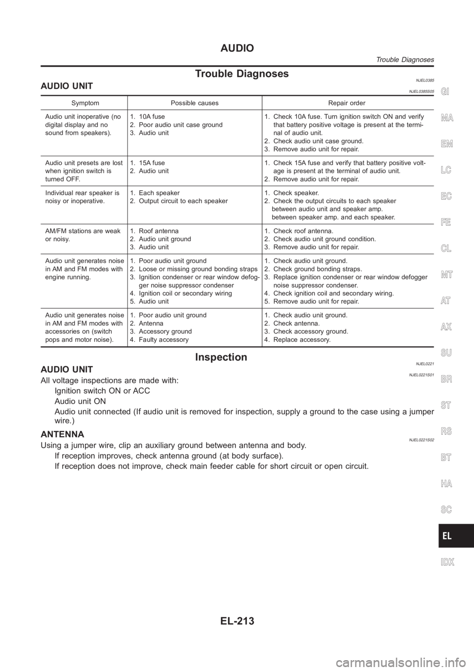
InspectionNJEL0221AUDIO UNITNJEL0221S01All voltage inspections are made with:
Ignition switch ON or ACC
Audio unit ON
Audio unit connected (If audio unit is removed for inspection, supply a ground to the case using a jumper
wire.)
ANTENNANJEL0221S02Using a jumper wire, clip an auxiliary ground between antenna and body.
If reception improves, check antenna ground (at body surface).
If reception does not improve, check main feeder cable for short circuit oropen circuit.
GI
MA
EM
LC
EC
FE
CL
MT
AT
AX
SU
BR
ST
RS
BT
HA
SC
IDX
AUDIO
Trouble Diagnoses
EL-213
Page 3109 of 3189
How to Handle BatteryNJSC0003CAUTION:
If it becomes necessary to start the engine with a booster
battery and jumper cables,
1) Use a 12-volt booster battery.
2) After connecting battery cables, ensure that they are
tightly clamped to battery terminals for good contact.
3) Never add distilled water through the hole used to check
specific gravity.
MEL040F
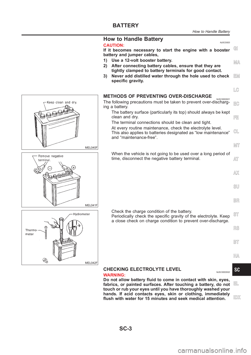
METHODS OF PREVENTING OVER-DISCHARGENJSC0003S01The following precautions must be taken to prevent over-discharg-
ing a battery.
The battery surface (particularly its top) should always be kept
clean and dry.
The terminal connections should be clean and tight.
At every routine maintenance, check the electrolyte level.
This also applies to batteries designated as “low maintenance”
and “maintenance-free”.
MEL041F
When the vehicle is not going to be used over a long period of
time, disconnect the negative battery terminal.
MEL042F
Check the charge condition of the battery.
Periodically check the specific gravity of the electrolyte. Keep
a close check on charge condition to prevent over-discharge.
CHECKING ELECTROLYTE LEVELNJSC0003S02WARNING:
Do not allow battery fluid to come in contact with skin, eyes,
fabrics, or painted surfaces. After touching a battery, do not
touch or rub your eyes until you have thoroughly washed your
hands. If acid contacts eyes, skin or clothing, immediately
flush with water for 15 minutes and seek medical attention.
GI
MA
EM
LC
EC
FE
CL
MT
AT
AX
SU
BR
ST
RS
BT
HA
EL
IDX
BATTERY
How to Handle Battery
SC-3