711 NISSAN ALMERA N16 2003 Electronic Repair Manual
[x] Cancel search | Manufacturer: NISSAN, Model Year: 2003, Model line: ALMERA N16, Model: NISSAN ALMERA N16 2003Pages: 3189, PDF Size: 54.76 MB
Page 1 of 3189
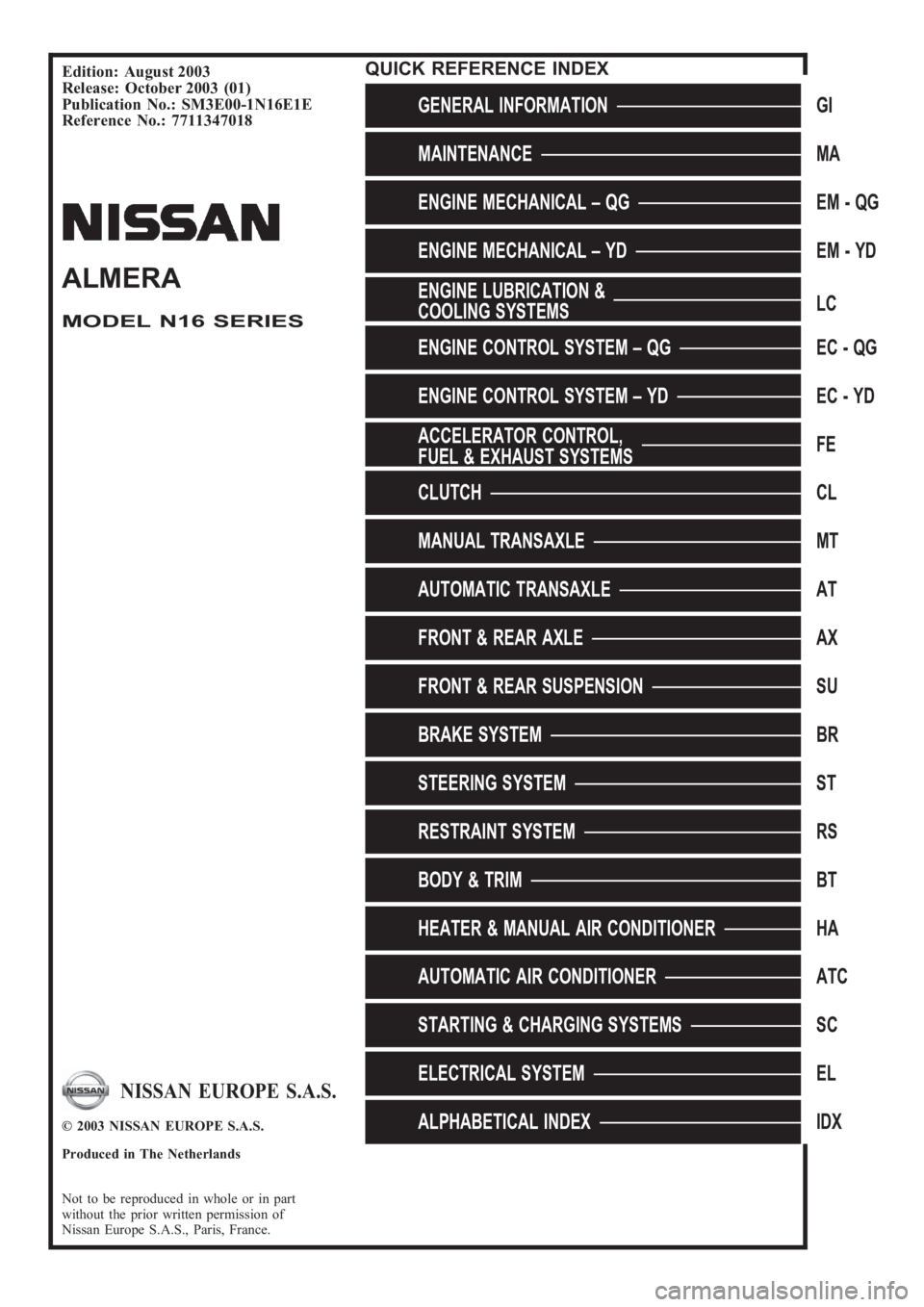
Edition: August 2003
Release: October 2003 (01)
Publication No.: SM3E00-1N16E1E
Reference No.: 7711347018
GENERAL INFORMATIONGI
MAINTENANCEMA
ENGINE MECHANICAL – QGEM-QG
ENGINE MECHANICAL – YDEM-YD
ENGINE LUBRICATION &
COOLING SYSTEMSLC
ENGINE CONTROL SYSTEM – QGEC - QG
ENGINE CONTROL SYSTEM – YDEC - YD
ACCELERATOR CONTROL,
FUEL & EXHAUST SYSTEMSFE
CLUTCHCL
MANUAL TRANSAXLEMT
AUTOMATIC TRANSAXLEAT
FRONT & REAR AXLEAX
FRONT & REAR SUSPENSIONSU
BRAKE SYSTEMBR
STEERING SYSTEMST
RESTRAINT SYSTEMRS
BODY & TRIMBT
HEATER & MANUAL AIR CONDITIONERHA
AUTOMATIC AIR CONDITIONERATC
STARTING & CHARGING SYSTEMSSC
ELECTRICAL SYSTEMEL
ALPHABETICAL INDEXIDX
ALMERA
MODEL N16 SERIES
NISSAN EUROPE S.A.S.
© 2003 NISSAN EUROPE S.A.S.
Produced in The Netherlands
Not to be reproduced in whole or in part
without the prior written permission of
Nissan Europe S.A.S., Paris, France.
QUICK REFERENCE INDEX
Page 233 of 3189
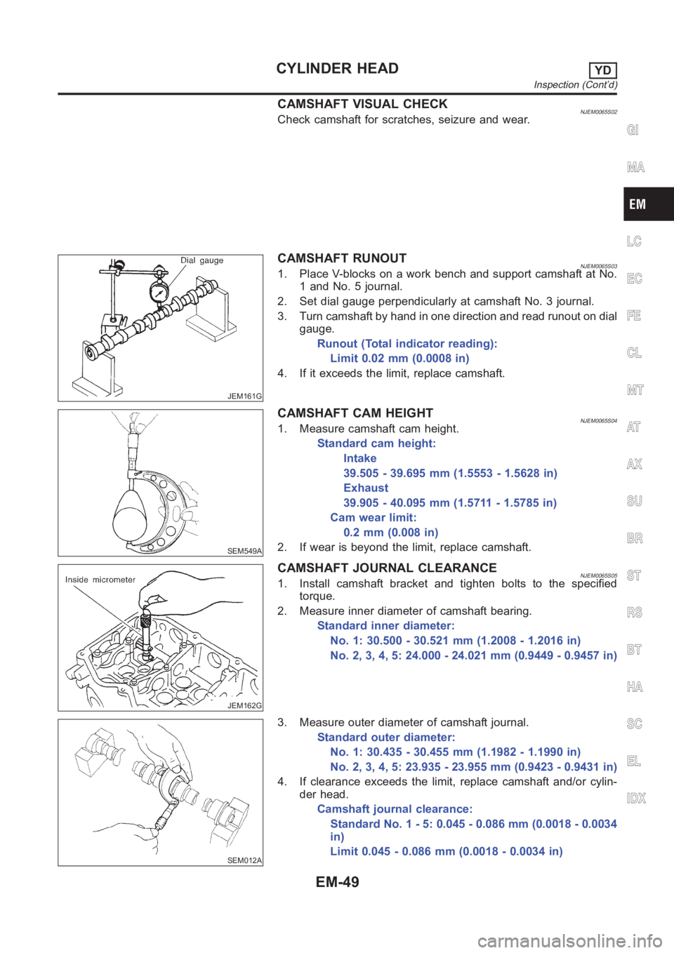
CAMSHAFT VISUAL CHECKNJEM0065S02Check camshaft for scratches, seizure and wear.
JEM161G
CAMSHAFT RUNOUTNJEM0065S031. Place V-blocks on a work bench and support camshaft at No.
1 and No. 5 journal.
2. Set dial gauge perpendicularly at camshaft No. 3 journal.
3. Turn camshaft by hand in one direction and read runout on dial
gauge.
Runout (Total indicator reading):
Limit 0.02 mm (0.0008 in)
4. If it exceeds the limit, replace camshaft.
SEM549A
CAMSHAFT CAM HEIGHTNJEM0065S041. Measure camshaft cam height.
Standard cam height:
Intake
39.505 - 39.695 mm (1.5553 - 1.5628 in)
Exhaust
39.905 - 40.095 mm (1.5711 - 1.5785 in)
Cam wear limit:
0.2mm(0.008in)
2. If wear is beyond the limit, replace camshaft.
JEM162G
CAMSHAFT JOURNAL CLEARANCENJEM0065S051. Install camshaft bracket and tighten bolts to the specified
torque.
2. Measure inner diameter of camshaft bearing.
Standard inner diameter:
No. 1: 30.500 - 30.521 mm (1.2008 - 1.2016 in)
No. 2, 3, 4, 5: 24.000 - 24.021 mm (0.9449 - 0.9457 in)
SEM012A
3. Measure outer diameter of camshaft journal.
Standard outer diameter:
No. 1: 30.435 - 30.455 mm (1.1982 - 1.1990 in)
No. 2, 3, 4, 5: 23.935 - 23.955 mm (0.9423 - 0.9431 in)
4. If clearance exceeds the limit, replace camshaft and/or cylin-
der head.
Camshaft journal clearance:
Standard No. 1 - 5: 0.045 - 0.086 mm (0.0018 - 0.0034
in)
Limit 0.045 - 0.086 mm (0.0018 - 0.0034 in)
GI
MA
LC
EC
FE
CL
MT
AT
AX
SU
BR
ST
RS
BT
HA
SC
EL
IDX
CYLINDER HEADYD
Inspection (Cont’d)
EM-49
Page 276 of 3189
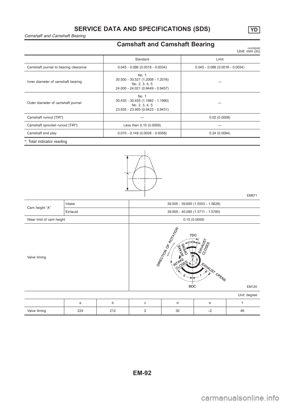
Camshaft and Camshaft Bearing=NJEM0080Unit: mm (in)
Standard Limit
Camshaft journal to bearing clearance 0.045 - 0.086 (0.0018 - 0.0034) 0.045 - 0.086 (0.0018 - 0.0034)
Inner diameter of camshaft bearingNo. 1
30.500 - 30.521 (1.2008 - 1.2016)
No. 2, 3, 4, 5
24.000 - 24.021 (0.9449 - 0.9457)—
Outer diameter of camshaft journalNo. 1
30.435 - 30.455 (1.1982 - 1.1990)
No. 2, 3, 4, 5
23.935 - 23.955 (0.9423 - 0.9431)—
Camshaft runout [TIR*] — 0.02 (0.0008)
Camshaft sprocket runout [TIR*] Less than 0.15 (0.0059) —
Camshaft end play 0.070 - 0.148 (0.0028 - 0.0058) 0.24 (0.0094)
*: Total indicator reading
EM671
Cam height “A”Intake 39.505 - 39.695 (1.5553 - 1.5628)
Exhaust 39.905 - 40.095 (1.5711 - 1.5785)
Wear limit of cam height0.15 (0.0059)
Valve timing
EM120
Unit: degree
abcde f
Valve timing 224 212 2 30 –2 46
SERVICE DATA AND SPECIFICATIONS (SDS)YD
Camshaft and Camshaft Bearing
EM-92
Page 338 of 3189
EC-8
Wiring Diagram .....................................................625
Diagnostic Procedure ...........................................626
DTC P1805 BRAKE SWITCH .................................628
Description ............................................................628
CONSULT-II Reference Value in Data Monitor Mode
.628
On Board Diagnosis Logic ....................................628
DTC Confirmation Procedure ...............................628
Wiring Diagram .....................................................629
Diagnostic Procedure ...........................................630
Component Inspection ..........................................632
HO2S1 HEATER .....................................................633
Description ............................................................633
CONSULT-II Reference Value in Data Monitor Mode
.633
Wiring Diagram .....................................................634
Diagnostic Procedure ...........................................635
Component Inspection ..........................................637
Removal and Installation ......................................637
HO2S2 HEATER .....................................................638
Description ............................................................638
CONSULT-II Reference Value in Data Monitor Mode
.638
Wiring Diagram .....................................................639
Diagnostic Procedure ...........................................640
Component Inspection ..........................................642
Removal and Installation ......................................642
IAT SENSOR ...........................................................643
Component Description ........................................643
Wiring Diagram .....................................................644
Diagnostic Procedure ...........................................645
Component Inspection ..........................................646
Removal and Installation ......................................646
HO2S1 .....................................................................647
Component Description ........................................647
CONSULT-II Reference Value in Data Monitor Mode
.647
Wiring Diagram .....................................................648
Diagnostic Procedure ...........................................649
Component Inspection ..........................................652
Removal and Installation ......................................653
HO2S2 .....................................................................654
Component Description ........................................654
CONSULT-II Reference Value in Data Monitor Mode
.654
Wiring Diagram .....................................................655
Diagnostic Procedure ...........................................656
Component Inspection ..........................................658
Removal and Installation ......................................659
IGNITION SIGNAL ..................................................660
Component Description ........................................660
Wiring Diagram .....................................................661
Diagnostic Procedure ...........................................664
Component Inspection ..........................................668
Removal and Installation ......................................669
EVAP CANISTER PURGE VOLUME CONTROL
SOLENOID VALVE .................................................670
Description ............................................................670
CONSULT-II Reference Value in Data Monitor Mode .670
Wiring Diagram .....................................................671
Diagnostic Procedure ............................................673
Component Inspection ..........................................676
Removal and Installation .......................................676
VSS ..........................................................................677
Description ............................................................677
Diagnostic Procedure ............................................677
POWER STEERING PRESSURE SENSOR ...........678
Component Description ........................................678
CONSULT-II Reference Value in Data Monitor Mode
.678
Wiring Diagram .....................................................679
Diagnostic Procedure ............................................680
Component Inspection ..........................................682
IVT CONTROL SOLENOID VALVE ........................683
Description ............................................................683
CONSULT-II Reference Value in Data Monitor Mode
.683
Wiring Diagram .....................................................685
Diagnostic Procedure ............................................686
Component Inspection ..........................................688
Removal and Installation .......................................688
PNP SWITCH ..........................................................689
Component Description ........................................689
CONSULT-II Reference Value in Data Monitor Mode
.689
Wiring Diagram .....................................................690
Diagnostic Procedure ............................................691
INJECTOR CIRCUIT ...............................................693
Component Description ........................................693
CONSULT-II Reference Value in Data Monitor Mode
.693
Wiring Diagram .....................................................694
Diagnostic Procedure ............................................695
Component Inspection ..........................................698
Removal and Installation ......................................
.698
FUEL PUMP CIRCUIT .............................................699
Description ............................................................699
CONSULT-II Reference Value in Data Monitor Mode
.699
Wiring Diagram .....................................................700
Diagnostic Procedure ............................................701
Component Inspection ..........................................703
Removal and Installation .......................................704
REFRIGERANT PRESSURE SENSOR ..................705
Component Description ........................................705
Wiring Diagram .....................................................706
Diagnostic Procedure ............................................707
Removal and Installation .......................................709
ELECTRICAL LOAD SIGNAL ................................710
Description ............................................................710
CONSULT-II Reference Value in Data Monitor Mode
.710
Wiring Diagram .....................................................711
Diagnostic Procedure ............................................712
MI & DATA LINK CONNECTORS ...........................715
Wiring Diagram—LHD Models ..............................715
Wiring Diagram—RHD Models .............................716
Page 1041 of 3189
![NISSAN ALMERA N16 2003 Electronic Repair Manual ELECTRICAL LOAD SIGNAL
EC-711
[QG (WITHOUT EURO-OBD)]
C
D
E
F
G
H
I
J
K
L
MA
EC
Wiring DiagramEBS00KMD
YEC311A](/img/5/57350/w960_57350-1040.png "NISSAN ALMERA N16 2003 Electronic Repair Manual ELECTRICAL LOAD SIGNAL
EC-711
[QG (WITHOUT EURO-OBD)]
C
D
E
F
G
H
I
J
K
L
MA
EC
Wiring DiagramEBS00KMD
YEC311A")
ELECTRICAL LOAD SIGNAL
EC-711
[QG (WITHOUT EURO-OBD)]
C
D
E
F
G
H
I
J
K
L
MA
EC
Wiring DiagramEBS00KMD
YEC311A
Page 1224 of 3189
MONITOR ITEM CONDITION SPECIFICATION
BARO SEN Ignition switch: ONAltitude
Approx. 0 m (0 ft): Approx. 100.62
kPa (1.0062 bar, 1.026 kg/cm
2,
14.59 psi)
Approx. 1,000 m (3,281 ft): Approx.
88.95 kPa (0.8895 bar, 0.907
kg/cm
2, 12.90 psi)
Approx. 1,500 m (4,922 ft): Approx.
83.16 kPa (0.8316 bar, 0.848
kg/cm
2, 12.06 psi)
Approx. 2,000 m (6,562 ft): Approx.
78.36 kPa (0.7836 bar, 0.799
kg/cm
2, 11.36 psi)
ECM Terminals and Reference ValueNJEC0709Specification data are reference values and are measured between each terminal and ground.
CAUTION:
Do not use ECM ground terminals when measuring input/output voltage. Doing so may result in dam-
age to the ECM’s transistor. Use a ground other than ECM terminals, such as the ground.
TERMI-
NAL
NO.WIRE
COLORITEM CONDITION DATA (DC Voltage)
313 L/WElectronic control fuel
injection pump[Engine is running]
Warm-up condition
Idle speedApproximately 0.1V
314 L/RElectronic control fuel
injection pump[Engine is running]
Warm-up condition
Idle speedApproximately 0.4V
316 PUElectronic control fuel
injection pump[Engine is running]
Warm-up condition
Idle speedApproximately 2.5V
317 PElectronic control fuel
injection pump[Engine is running]
Warm-up condition
Idle speedApproximately 2.5V
On Board Diagnosis LogicNJEC0710This self-diagnosis has the one trip detection logic.
DTC Malfunction is detected when .... Check Items (Possible cause)
P1600
0703Injection pump control unit receives incorrect volt-
age signal from ECM continuously.Harness or connectors
(Electronic control fuel injection pump circuit is
open or shorted.)
Electronic control fuel injection pump
SEF817Y
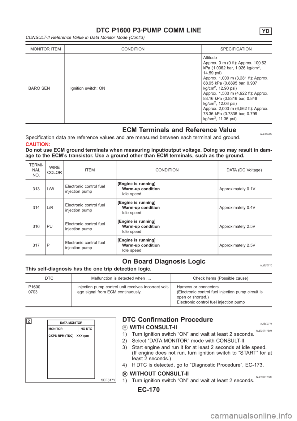
DTC Confirmation ProcedureNJEC0711WITH CONSULT-IINJEC0711S011) Turn ignition switch “ON” and wait at least 2 seconds.
2) Select “DATA MONITOR” mode with CONSULT-II.
3) Start engine and run it for at least 2 seconds at idle speed.
(If engine does not run, turn ignition switch to “START” for at
least 2 seconds.)
4) If DTC is detected, go to “Diagnostic Procedure”, EC-173.
WITHOUT CONSULT-IINJEC0711S021) Turn ignition switch “ON” and wait at least 2 seconds.
DTC P1600 P3·PUMP COMM LINEYD
CONSULT-II Reference Value in Data Monitor Mode (Cont’d)
EC-170
Page 1394 of 3189
SMT710DB
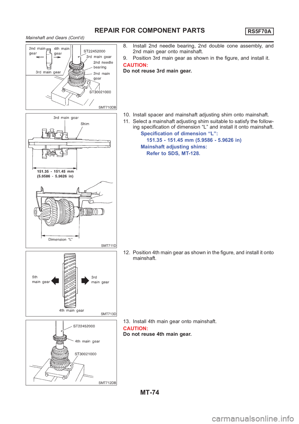
8. Install 2nd needle bearing, 2nd double cone assembly, and
2nd main gear onto mainshaft.
9. Position 3rd main gear as shown in the figure, and install it.
CAUTION:
Do not reuse 3rd main gear.
SMT711D
10. Install spacer and mainshaft adjusting shim onto mainshaft.
11. Select a mainshaft adjusting shim suitable to satisfy the follow-
ing specification of dimension “L” and install it onto mainshaft.
Specification of dimension “L”:
151.35 - 151.45 mm (5.9586 - 5.9626 in)
Mainshaft adjusting shims:
Refer to SDS, MT-128.
SMT713D
12. Position 4th main gear as shown in the figure, and install it onto
mainshaft.
SMT712DB
13. Install 4th main gear onto mainshaft.
CAUTION:
Do not reuse 4th main gear.
REPAIR FOR COMPONENT PARTSRS5F70A
Mainshaft and Gears (Cont’d)
MT-74
Page 2079 of 3189
TROUBLE DIAGNOSIS
ATC-99
C
D
E
F
G
H
I
K
L
MA
B
AT C
Memory FunctionEJS0022Y
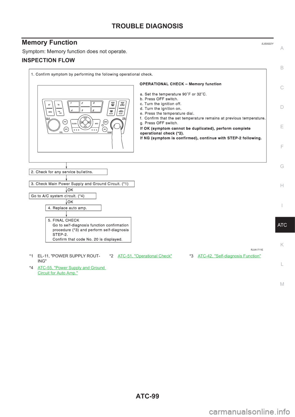
Symptom: Memory function does not operate.
INSPECTION FLOW
*1 EL-11, "POWER SUPPLY ROUT-
ING"*2AT C - 5 1 , "Operational Check"*3AT C - 4 2 , "Self-diagnosis Function"
*4AT C - 5 5 , "Power Supply and Ground
Circuit for Auto Amp."
RJIA1711E
Page 2102 of 3189
ATC-122
HEATER & COOLING UNIT ASSEMBLY
HEATER & COOLING UNIT ASSEMBLY
PFP:27110
Removal and InstallationEJS0020A
REMOVAL
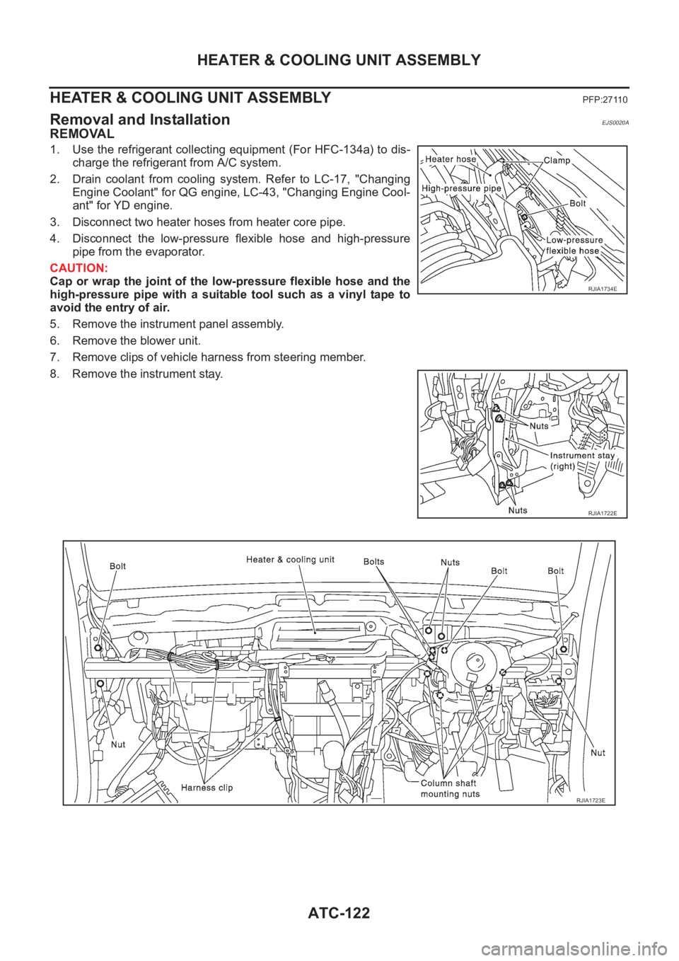
1. Use the refrigerant collecting equipment (For HFC-134a) to dis-
charge the refrigerant from A/C system.
2. Drain coolant from cooling system. Refer to LC-17, "Changing
Engine Coolant" for QG engine, LC-43, "Changing Engine Cool-
ant" for YD engine.
3. Disconnect two heater hoses from heater core pipe.
4. Disconnect the low-pressure flexible hose and high-pressure
pipe from the evaporator.
CAUTION:
Cap or wrap the joint of the low-pressure flexible hose and the
high-pressure pipe with a suitable tool such as a vinyl tape to
avoid the entry of air.
5. Remove the instrument panel assembly.
6. Remove the blower unit.
7. Remove clips of vehicle harness from steering member.
8. Remove the instrument stay.
RJIA1734E
RJIA1722E
RJIA1723E
Page 2155 of 3189
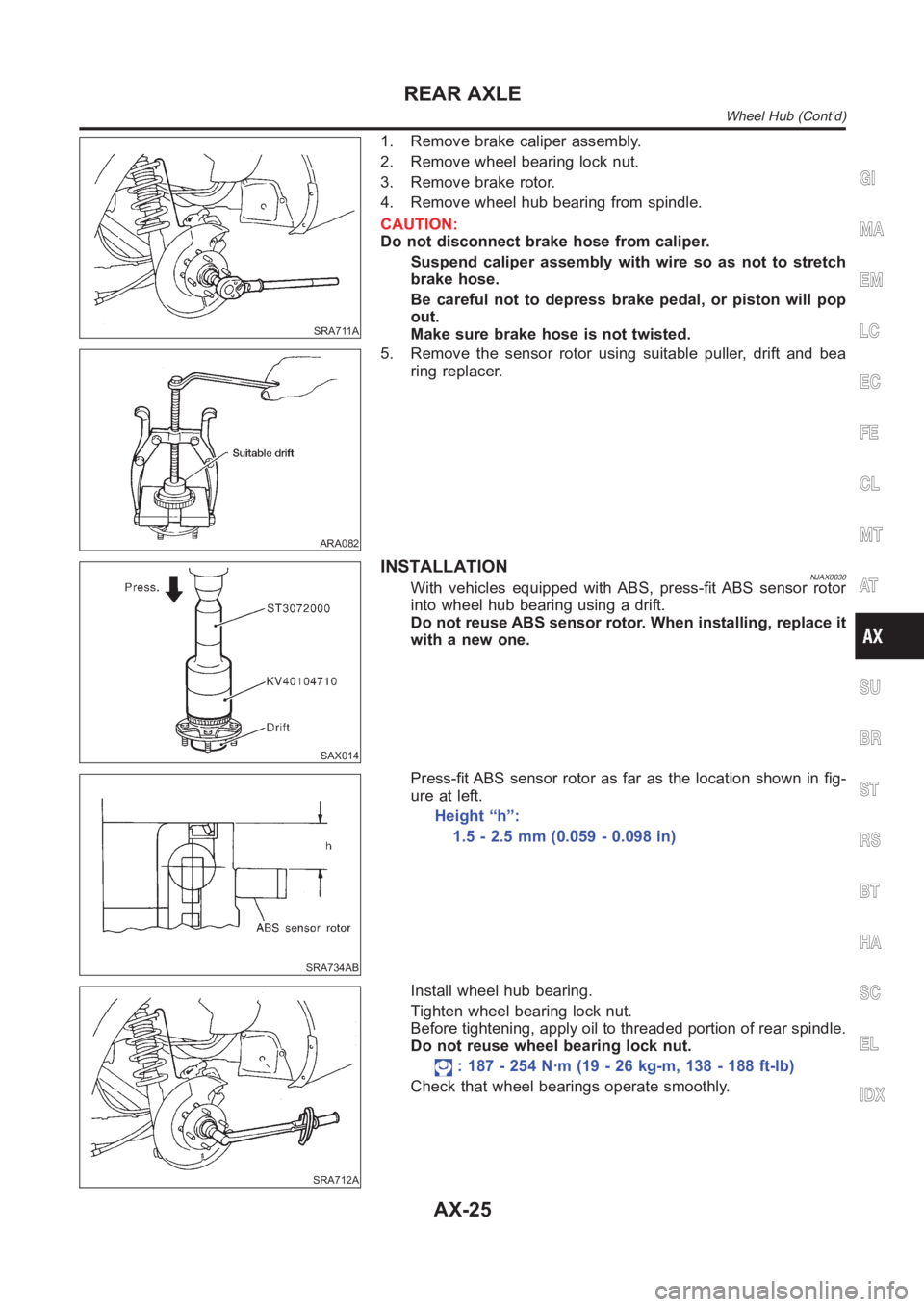
SRA711A
1. Remove brake caliper assembly.
2. Remove wheel bearing lock nut.
3. Remove brake rotor.
4. Remove wheel hub bearing from spindle.
CAUTION:
Do not disconnect brake hose from caliper.
Suspend caliper assembly with wire so as not to stretch
brake hose.
Be careful not to depress brake pedal, or piston will pop
out.
Make sure brake hose is not twisted.
ARA082
5. Remove the sensor rotor using suitable puller, drift and bea
ring replacer.
SAX014
INSTALLATIONNJAX0030With vehicles equipped with ABS, press-fit ABS sensor rotor
into wheel hub bearing using a drift.
Do not reuse ABS sensor rotor. When installing, replace it
with a new one.
SRA734AB
Press-fit ABS sensor rotor as far as the location shown in fig-
ure at left.
Height “h”:
1.5 - 2.5 mm (0.059 - 0.098 in)
SRA712A
Install wheel hub bearing.
Tighten wheel bearing lock nut.
Before tightening, apply oil to threaded portion of rear spindle.
Do not reuse wheel bearing lock nut.
: 187 - 254 N·m (19 - 26 kg-m, 138 - 188 ft-lb)
Check that wheel bearings operate smoothly.
GI
MA
EM
LC
EC
FE
CL
MT
AT
SU
BR
ST
RS
BT
HA
SC
EL
IDX
REAR AXLE
Wheel Hub (Cont’d)
AX-25